1
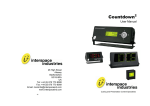
ClockWatch
User Manual
Cueing and Presentation Control Specialists
Contents:
Introduction
3
Environmental / Electrical Compliance
3
Safety Instructions
4
Diagrams
5
Regulations Compliance
6
Operating Instructions
6
Programming
7
Technical Support Contact
7
2
Introduction
ClockWatch combines clear traffic-light type signalling with a simple-to-use timekeeping
system. The intuitive control module has been designed especially for non-technical users so
that formal timekeeping can be easily managed in a wide variety of applications.
Signalling to speakers to ensure everything runs to time is the key to a smooth, professional
meeting and ClockWatch silently prompts presenters when to speak (green light), when to
summarise (amber light) and when to finish (red light). Feed back to a timekeeper and/or the
meeting chairperson can also be provided via a variety of visual or numeric displays.
Designed for reliability and versatility, ClockWatch is based on AV-industry-proven rugged
design, uses readily available 3pin XLR (mic) cable connectors and the system can be set up
in just 1-2 minutes, or be permanently installed if required.
Meeting Control Made Easy!
We hope ClockWatch exceeds your expectations and welcome any feedback that you have
about this or any of our products.
Thank you.
The Interspace Industries Team
www.interspaceind.com
Environmental
WEEE and RoHS Compliance. ClockWatch and its associated accessories have been
manufactured and sold in accordance with the requirements of the EC WEEE and RoHS
directives. Please return all end-of-life items to your supplier, or Interspace Industries directly,
for appropriate disposal.
Packaging Materials:
Cardboard box:
Grade 150 K/T ‘B’ (Single Walled Corrugated - Brown Kraft)
Protective Foam: Grade HLB 22 Grey Foam (High Load Bearing)
Electrical
CE Mark. ClockWatch and its associated accessories have been designed, manufactured
and certified to comply with all requirements of the European CE standard.
3
Safety Instructions
All safety and operating instructions should be read before this product is operated and
should be retained for further reference. Please adhere to all the warnings on this product
and in these operating instructions. Please follow these instructions carefully.
Power. Only use the power source indicated on the device. Devices equipped with a
grounded plug should only be used with a grounded type outlet. In no way should this
grounding be disconnected, modified or suppressed.
Power Supply Lead. To unplug the device always pull by the plug itself, not the power
supply lead. The power source outlet should always be near the MicroCue main unit and
easily accessible. Ensure the power supply lead cannot be walked on or damaged by items
placed on or against it. Do not use if the power supply lead is damaged. Using the device
with a damaged power supply lead may expose you to electric shock or other hazards.
Check the condition of the power supply lead regularly. Contact your dealer or service centre
immediately for a replacement if damaged.
Keep Away From Harmful Substances
To prevent the risk of electric shock and fire, do not expose this device to rain, humidity or
intense heat sources (such as radiators or direct sunlight). Avoid using this equipment in
environments where there is excessive heat, dust, moisture, chemicals, vibration or
mechanical shocks.
Slots and Openings. These are designed into the device for ventilation and to avoid
overheating. Always ensure these openings remain clear. Do not attempt to insert
anything into these openings under any circumstances. If liquids have been spilled on,
or objects have fallen into the product it must be checked by a qualified technician before reusing.
Connections. All inputs and outputs (except for power input) are TBTS defined under
EN60950.
•
•
DO NOT OPEN SYSTEM DUE TO HIGH VOLTAGE.
DO NOT IMMERSE IN WATER.
If you have any queries regarding these safety instructions or how to maintain the unit please
do not hesitate to contact us on:
+44(0)870 770 8088
Servicing. Do not attempt to service this product yourself. Opening or removing covers and
screws may expose you to electric shocks or other hazards. Refer all servicing to qualified
service personnel.
4
Diagrams
Figure 1: ClockWatch Connections Diagram
R
D
A
G
P1
P2
O1
O2
P3
O3
P4
1
O4
2
M
Figure 2: ClockWatch Front and Rear Panel Controls
5
DECLARATION OF CONFORMITY
We declare under our sole responsibility that the product
ClockWatch
To which this declaration relates is in conformity with the following standards or other normative documents:
EN55103-1 & EN55103-2 1966 (Specific for professional Audio Visual Products). Used in
environment as defined under E2 Commercial and Light industry (example Theatres)
EN60950-1 : 2000
Following the provisions of the EEC Directive 89/336/EEC and 73/23/EEC
Dave Humphrys
Managing Director, Interspace Industries Ltd
Issued on: Date 14 May 2008
Operating Instructions
Unpacking and Connections. Unpack the main unit and place on a flat surface within easy
access for the Operator. Adjust the angle of the main unit by loosening the bracket securing
fasteners on each side of the main unit and re-tightening once the most comfortable angle is
achieved.
Position the LightTower and any other display units for best viewing and connect the LightTower(s) to connections
&
, and any numeric or intelligent lamps to connections
O1
O3
O2
& O4 on the rear panel of the main unit using 3-pin XLR (mic) cables (see figures 1&2). The
maximum combined cable distances can be as much as 100m (300ft).
Connect the IEC power cable
M
to ClockWatch
and switch on the power at the source.
Quick Start Operation - Manual Mode. By simply pressing any of the LightTower lamp
control buttons R , A or G , the corresponding lamp on the LightTower and/or visual
displays will illuminate accordingly. The selected lamp will remain illuminated until either the
same button is pressed again (this extinguishes the lamp), or an alternative coloured lamp is
pressed. It is not possible to have more than one coloured lamp illuminated.
By pressing the PAUSE button 1 while any of the LightTower lamps are illuminated, the
lamp will flash intermittently, thus signalling that the time keeping has been paused. Pressing
the PAUSE 1 again will stop the lamp from flashing.
Quick Start Operation -Auto Mode. (Refer to ‘Programming’ section overleaf for instructions on how to pre-program the preset time sequence buttons). By pressing either of the
preset time sequence buttons P1 - P4 , the pre-programmed timer sequence starts immediately and the LightTower changes colours according to the pre-programmed timing profile. At
any time during the timer sequence, the PAUSE button 1 can be pressed to pause the
sequence. While paused, the LightTower lamp will flash intermittently to signal that the sequence has been paused. To resume the timing sequence, press the PAUSE 1button
again.
6
Should it be necessary to cancel a timing sequence, simple press the RESET button
This extinguishes all displays and resets the timer display D .
2
.
At any time while a preset timing sequence is running, any of the LightTower lamp control
buttons R , A or G can be pressed. This immediately illuminates whichever lamp has
been selected and cancels the timer sequence.
Programming Preset Timing Sequences.
1.
After resetting ClockWatch by briefly pressing the RESET button 2 , press and hold the
RESET button 2 , together with whichever one of the preset time sequence buttons
P1 - P4 that you wish to program. Hold both buttons down for around 5 seconds.
When the preset button glows brighter, ClockWatch is now in programming mode and
you can release both buttons. When programming a new timing sequence, the system
assumes the LightTower is always going to start from Green when the timing sequence
commences.
2.
To program the time interval until the LightTower turns from Green to Amber; pressing
the PAUSE button 1 increases the time interval by 5 seconds. To decrease the time
interval, press the PAUSE button 1 while holding down the RESET button 2 . The
numeric display D updates with each press of the PAUSE button 1 so you can see
the time interval you are programming.
3.
When the required interval has been programmed, release all buttons then momentarily
press the AMBER button A . The system is now ready to program the time interval until
the LightTower changes from Amber to Red.
4.
To program the time interval until the LightTower changes from Amber to Red, repeat
step 2 above. When the required interval has been programmed, momentarily press the
RED button R . The system then stores the new sequence and resets. This new
sequence will now run each time the PRESET button that was chosen in 1 above is
pressed.
For Technical Support or Sales Enquiries
Interspace Industries Head Office:
+44 (0) 870 770 8088
Emergency Technical Support Hot Line:
+44 (0) 7976 385046
Website:
www.interspaceind.com
7
28 High Street
Arlesey
Bedfordshire
SG15 6RA
UK
Tel: +44 (0) 870 770 8088
Fax: +44 (0) 870 770 8089
Email: [email protected]
www.interspaceind.com
8