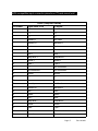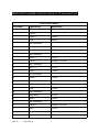
1
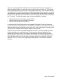
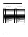
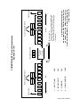
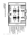
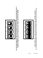
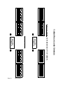
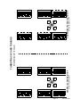
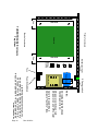
ATTENTION! ATTENTION!
All TurboTrack2 enclosures
now wired to ILDA Standard
wiring specifications. 01/01/2000
T2
TurboTrack
versions 2.0 and 2.0b
Maximum Performance Servo Amplifier for
Galvanometer Scanners
Lighting Systems Design, Inc.
4625 Winter Garden Road, Suite A-2
Orlando, Florida 32811-1777 U.S.A.
Phone 407-299-9504 • Fax 407-299-3965
www.lsdi.com
Page 1 Rev 10/10/01
Pagepage
This
2 Rev
intentionally
10/10/01 left blank.
TURBOTRACK2 SCANNER DRIVER AMPLIFIER
INTRODUCTION
The TurboTrack2 (T2) is a dual-channel servo amplifier designed for use with optical scanners.
In the laser display industry, the most commonly used models of scanner are the G 120D (or
DT) from General Scanning and the 6800 series scanner from Cambridge Technology.
T2 is a two-layer printed circuit board measuring 9 inches by 9 inches. Large heat sink fins are
attached to each side of the card, increasing the board's footprint to 9.5 inches wide by 9
inches in length by 2.5 inches in height. Fan-cooling of this card will greatly increase its
performance characteristics as well as prevent overheating of some power components.
The following features summarize the most important design benefits of the TurboTrack2
scanner driver amplifier:
>
>
>
>
>
>
>
>
>
>
>
>
>
Angle Intelligence -H-bridge drive -High K low-frequency damping for the CTI 6800 series scanners
Input signal limiting
Position and velocity outputs
A(utomatic) G(ain) C(ontrol) for position transducer
Output current limiting
Dual controls for high speed/low speed operation
Differential inputs
Input polarity switching
Signal pre-emphasis
Position scale and balance for CTI 6800 series scanners
DC offset bi-color LED indicators
Most important for the laser display user is TurboTrack2’s stable performance at high speeds.
Extensive testing has shown that the ILDA test pattern can easily be scanned at 24,000
vectors per second at a scan angle of 20 degrees optical, using G120D scanners.
INPUT CONNECTOR
The input to TurboTrack2 is a DB 15 male connector. Differential inputs are recommenced. If
single-ended (or unbalanced) inputs are used, both negative inputs should be tied to signal
ground. Simultaneous position, velocity, and drive current signals are also available from the
input connector.
OUTPUT CONNECTOR
The output connectors are both DB- 15 female. These are directly compatible with General
Scanning G120D scanners. Cambridge Technology's scanner cable design requires a
modification to replace the DB-9 connector with a DB- l 5 male connector.
Page 3 Rev 10/10/01
Whereas the General Scanning G120D scanners are driven with the H-bridge, the 6800 series
scanners achieve more stable performance with single-ended drive. Galvo low is therefore tied
to ground for operation with the 6800 series scanners (see diagram, page 15). DB-9 to DB- l 5
adapters are not recommended. Scanner cables can be up to l 0 feet without any visible
diminishing of scanner performance.
POWER SUPPLY
The TurboTrack2 requires a bipolar supply of +/-20 Volts DC as a minimum, and +/- 28 Volts
DC as a maximum. LSDI recommends a minimum continuous current rating of 3 Amperes.
When running CTI 6800 series scanners, a higher current capacity is desirable. Best
performance comes with the use of a regulated power supply; however, a "raw" DC supply
(transformer, full-wave bridge rectifiers and filter capacitors) will also work well. Switch mode
supplies can also be used.
COOLING
The power output stage of the TurboTrack2 uses the LM12CLK from National Semiconductor.
This is a power operational amplifier that can dissipate 150 watts of power. For this reason, it is
highly recommended that the TurboTrack2 be fan-cooled wherever possible. The large heat
sinks are constructed of industry-standard Aavid heat sink material, but some air flow is
essential for reliable operation. This is particularly important when the amplifier is mounted in a
chassis or rack-mount enclosure.
TurboTrack2 Adjustments
The TurboTrack2 is a 2-channel card. It also gives the user the ability to have 2 different
tunings on each card, an "A" tuning and a "B" tuning. In practice, this lets the user set one
tuning for l type of scanner and the second tuning for another type of scanner, or set both
tunings for the same scanners but different speeds, i.e. 12,000 points per second and 24,000
points per second. There are several useful combinations available.
No matter the scanner models or designated use for each tuning, the adjustments are the
same for each axis. The primary adjustments are as follows:
>
>
>
>
>
position offset
input gain
servo gain
damping
high damping
These adjustments are made via 15-turn trimmer potentiometers located at one end of the T2
card. There are two sets of potentiometers for each axis, representing the "A" tuning and the
"B" tuning capability of the circuit.
Page 4 Rev 10/10/01
From the outside of the card inward, the order of adjustments is as follows: position offset,
input gain, servo gain, damping and high damping.
The trimmer potentiometers are separated in the middle by a toggle-type DIP switch (GrayhIll
p/n 76STD02). This is the scan polarity inversion switch. Use this switch to change the left/
right, up/down orientation of the laser graphic image.
Other adjustments available to the user are DIP switches located above and perpendicular to
the trimmer potentiometers. These ganged DIP switches (Grayhill p/n 78B04) can be selected
to use either General Scanning or Cambridge Technology scanners, as well as select the "A"
or "B" tuning. These controls can only be accessed from the top of the card.
There are two additional "top" adjust trimmer potentiometers on the T2, both for use with the
CT16800 series scanners. One is Position Scale, and the second is Position Balance.
These are set at the factory and should not require further adjustment.
Before performing any adjustments, verify that ail supplemental components are operating
normally, i.e. power supply, scanner connections, or input signal to the scanner amplifier.
Adjustment Procedure: General Scanning
>
>
>
>
>
>
>
>
>
>
>
>
>
>
>
Scan a square wave test pattern at a vector speed of 9 to l 0 kilohertz.
Make sure ail trimpots are fully counter-clockwise, except the position offset.
Center the position offset.
Connect an oscilloscope or a digital voltmeter (DVM) to the position outputs.
Remove the fuses.
Apply power to the amplifier.
Adjust the position offset for 0 volts, each axis.
Turn off power to the amplifier and replace the fuses in the fuse clips.
Re-apply power to the amplifier. Turn input gain eight turns clockwise.
Slowly adjust servo gain until scanner begins to operate.
Adjust damping to correct overshoot. Use only normal damping; do not use high frequency
damping, as damage to the scanners or the board may occur.
Increase input gain until laser image is about 1/2 size.
Adjust servo gain to increase speed, then compensate with damping.
Once the system is optimized, increase input gain for full size. The AURA Technologies'
test pattern is recommended. If the interior circle begins to distort, maximum gain has been
reached. Reduce gain to point just before distortion occurs.
Set input polarity toggle DIP switch for correct image orientation.
Page 5 Rev 10/10/01
? NOTE: Servo gain control on T2 is a true servo gain. With this
control turned down (counter-clockwise) no scanning will occur. If
you are trouble-shooting a "no scanning problem" and you have
verified a good signal going to your scanners, be sure to check the
servo gain adjustment.
Adjustment Procedure: Cambridge Technology
As the Cambridge Technology's 6800 series scanners (6800H and 6800HP) do not have a
torsion rod or other center return mechanism, the scanners may be directing the beam to most
any direction when not energized. When beginning the calibration procedure, the scanner will
suddenly move to the approximate center when the servo gain is sufficient to drive the
scanner. The oscilloscope/digital voltmeter centering procedure may be done with the
scanners disconnected from the board.
> Scan a square wave test pattern at a vector speed of 9-10 kHz.
> Make sure ail trimpots are fully counter-clockwise, except the position offset, which should
>
>
>
>
>
>
>
>
>
be approximately centered.
Power up the amplifier.
Turn input gain eight turns clockwise.
Slowly adjust servo gain until scanner begins to operate.
Adjust damping to correct overshoot. Normal damping affects large changes. Hi damping is
used to correct small errors, in conjunction with the normal damping. Hi damping corrects
errors of high spatial frequency.
Increase input gain until image is about 1/2 size.
Repeat steps 1-4 for the opposing axis.
Adjust servo gain to increase speed, compensate with damping. Use both Hi and normal
damping to optimize velocity profile.
Once the system is optimized, increase input gain for full size. The ILDA or Auratech test
pattern is recommended. If the interior circle begins to distort, maximum size has been
reached. Reduce gain to the point just before distortion occurs.
Set input polarity for the correct orientation.
Adjustment Procedure: Mode Selection
There are several DIP switches accessible from the top of the TurboTrack board. These should
only be switched with the power OFF. This is very important, as damage to the board or the
scanners may result otherwise. These switches are shown on a diagram accompanying this
manual.
Page 6 Rev 10/10/01
There are four (4) ganged DIP switches at the front of the TurboTrack card for selection of
different amplifier tunings. On each side, only one switch bank should be in the "ON" position.
Looking at the card from an end-on view, "ON" is away from the user, "OFF is toward the user.
The outside bank "A" affects the outside four adjustment potentiometers: input size, servo gain,
normal damping and high frequency damping. The position offset controls at the outer edge of
the card are not affected. The inner bank of controls accessed by the "B" switch are identical to
the "A" controls. The dual adjustments allow for many possibilities, for example
> High speed scanning versus lower speed scanning
> General Scanning versus Cambridge Technology
> Main scanner set and spare scanner set
In the center of the TurboTrack are four more ganged DIP switches. These are the primary
controls to switch from GS Operation to CT operation. Ail switches to the outside of the card is
General Scanning mode; ail switches to the center of the card is Cambridge Technology mode.
(Please see the TurboTrack2 configuration diagram in this manual.)
Closes to the fuses are two (2) quad DIP switches. SW # 181, 182, 381 and 382 are used to
add pre-emphasis to the command signal. This increases the effective bandwidth of the
scanners by as much as 6 kHz. For example, if the scanners are tuned for 24K points per
second operation, switching on pre-emphasis will allow them to run images digitized to run at
30K. SW# SB and SC are on for ail modes of operation. SW # 222 and 422 are off for GS
Mode and on for CT mode. This is output stage compensation for the 6800H and 6800HP
scanners.
Page 7 Rev 10/10/01
Connector pinouts on T2 stand-alone card
INPUT CONNECTOR
(D Sub Miniature 15 pin male)
OUTPUT CONNECTOR
(D Sub Miniature 15 pin female)
Pin Number
Pin Number
1
X axis positive
1
Galvo High
2
X axis negative
2
Galvo Low
3
X position output signal
3
Position plus
4
X velocity output signal
4
Position ground
5
Y velocity output signal
5
Heater ground
6
Y position output signal
6
- 15 VDC
7
Y axis negative
7
Heater drive
8
Y axis positive
8
GSI (General Scanning) AGC out
9
X axis ground
9
Galvo High
10
X axis ground
10
Galvo Low
11
X axis current output signal
11
Position minis
12
Not connected
12
GSI (General Scanning) AGC in
13
Y axis current output signal
13
Scanner ground
14
Y axis ground
14
Cambridge Technology AGC out
15
Y axis ground
15
Thermal in
Page 8 Rev 10/10/01
Page 9 Rev 10/10/01
100K
4. HIGH DAMPING
3
20K
2
3. DAMPING
LEFT
1
20K
4
2. SERVO GAIN
3
“B” tuning
20K
2
“A” tuning
1. INPUT GAIN
1
Position offset
Scanner tuning DIP switches
4
DB15 Male
(Input)
Connector
POLARITY SWITCH
2
4
RIGHT
1
3
2
1
Bi-color LED’s
These LED’s are on during calibration and
during normal operation of the amp. The
LED indicates that current is going through
the scanner.
3
“A” tuning
Position offset
Lighting Systems Design, Inc.
4625 Winter Garden Road, Suite A-2
Orlando, Florida 32811-1777 U.S.A.
Phone 407-299-9504 • Fax 407-299-3965
www.lsdi.com
4
“B” tuning
Scanner tuning DIP switches
TURBOTRACK2 Trim Pot Adjustments
Expanded View
OUTPUT
Power terminal
block
OUTPUT
12
LM
GSI Mode
12
LM
CT Mode
2 AMP
FUSES
GSI Mode
Pre-emphasis
OFF
A
TRIM POTENTIOMETERS
B
Scanner tuning DIP switches
GSI Mode
Pre-emphasis
ON
INPUT
POLARITY SWITCH
CT Mode
Pre-emphasis
OFF
GSI Mode
B
Scanner tuning DIP switches
A
TRIM POTENTIOMETERS
TURBOTRACK2 CONFIGURATION
MAIN ELEMENTS
REV. 1999/07/10
KEY:
Power output stage
LM12CLK
Output connectors
DB-15 female
Input connector
DB-15 male
Fuses 3AG type Fastblo
GSI General Scanning
(GSI Luminonics)
CT
Cambridge Technology
WARNING!!
Before changing any scanner
settings or tunings on T2
card, turn power to the card
OFF! You risk damage to T2
card or scanners if power is
not turned off before
changing settings.**
**Pre-emphasis can be turned on or
off when card is powered up.
Rev 10/10/01
Page 10
HEAT SINK
HEAT SINK
Page 11
Rev 10/10/01
2
3
4
2
3
4
THIS IS A DETAIL VIEW OF THE 4-POSITION DIP SWITCH THAT HAS BEEN “GANGED”.
ALL 4 SWITCHES ARE JOINED TOGETHER VIA A BAR PLACED ACROSS THE TOP OF THE SWITCH.
O
N
1
PLEASE NOTE THE DIRECTION OF THE DIP SW ITCH FOR THE “ON” POSITION. THE SWITCH MUST BE PUSHED
TOWARD THE NUMERICAL INDICATOR (THE DIRECTION OF THE ARROW) TO BE IN THE “ON” POSITION.
THIS IS A DETAIL VIEW OF THE GRAYHILL 4-POSITION DIP SWITCH USED ON THE TURBOTRACK CARD.
O
N
1
O
N
O
N
1
1
2
2
3
3
4
4
O
N
O
N
1
1
TURBOTRACK CARD TUNINGS
3
3
4
4
THIS IS “B” TUNING.
DB15 INPUT
CONNECTOR
O
N
O
N
1
1
2
2
3
3
4
4
THIS IS “A” TUNING. NOTE DIRECTION OF “ON” ARROW.
2
2
DB15 INPUT
CONNECTOR
O
N
O
N
1
1
2
2
3
3
4
4
Rev 10/10/01
Page 12
4
S
L
3
D
2
O
N
I
4
3
2
1
4
3
1
1
2
4
O
N
O
N
3
O
N
O
N
4
(THIS DRAWING NOT TO SCALE)
4
O
N
4
2
3
4
Page 13
3
2
O
N
O
N
with pre-emphasis OFF
3
CAMBRIDGE TECHNOLOGY MODE
2
with pre-emphasis OFF
1
1
1
GENERAL SCANNING MODE
4
3
2
S
3
L
2
2
D
1
1
1
I
4
3
2
1
4
4
3
3
2
2
O
N
1
1
O
N
O
N
TURBOTRACK CARD TUNINGS
O
N
Rev 10/10/01
Front of enclosure
Bridge
rectifier
Fuse
AC indicator light
Fan
T2 Card
Fan
Back of enclosure
Heat Sink
TURBOTRACK2 Enclosure
Top View
Card is fused with a 2
Ampere “fast blo” fuse.
DC power switch can turn
DC power on and off to card;
AC indicator lights shows
that AC power is on;
Notes:
DC power switch
Capacitors
Transformer
Power Entry Module
Lighting Systems Design, Inc.
4625 Winter Garden Road, Suite A-2
Orlando, Florida 32811-1777 U.S.A.
Phone 407-299-9504 • Fax 407-299-3965
www.lsdi.com
Rev 10/10/01
Page 14
Heat Sink
N/A
N/A
N/A
2
4
7
N/A
N/A
N/A
7
8
9
10 N/A
2 conductor cable with shield/drain 24 gauge
4 conductor cable with shield/drain 24 -28 gauge
All pins gold flash
Shield/drain from 2 conductor cable should isolated
from shield/drain from 4 conductor cable
5. Use heatshrink tubing every 12” to secure 2 conductor
and 4 conductor wires to each other along 10 feet
6. D-Sub 15 pin connector to have back shell
1.
2.
3.
4.
15 N/A
Rev 10/10/01
Lighting Systems Design, Inc.
Orlando, Florida
2
3
4
5
CAGE CODE
SHEET
CT-010731
John Robert Birchman
DWG NO
Cambridge 6800 Scanner Cable
For Turbo Track Amplifier
None
A
SCALE
SIZE
TITLE
P2
P1
1 of 1
CAM68T Scanner Cable
Insertion (back) view
1
N/A
6
12 N/A
10
N/A
2
6
Motor -
6
BLK
Galvo High
1
7
Motor +
5
RED
13 Scanner Gnd
Heater Gnd
8
Shield #1
8
5
9
AGC Out
3
GRN
14 CTI AGC Out
4
10 Diode Common
Position +
3
lb
la
WHT
9
Position Gnd
P2
1
RED
BLK
P1
AMP 102387-1
10 Feet
Scanner Side
Amplifier Side
D-Sub 15 pin male
11 Position -
Notes:
Page 15
A
REV
Amplifier Side
D-Sub 15 pin male
10 Feet
Scanner Side
D-Sub 15 pin female
8
3
GSI AGC out
Position +
P2
Position +
BLK
P1
3
GSI AGC out
RED
8
Position Gnd
11 Position -
4
Galvo High
WHT
1
Galvo Low
11 Position -
Position Gnd
RED
2
12 GSI AGC in
4
Galvo High
BLK
GRN
1
Galvo Low
12 GSI AGC in
2
N/A
5
9
N/A
N/A
Galvo High
13 Scanner Gnd
9
N/A
6
N/A
13 Scanner Gnd
5
N/A
7
10 Galvo Low
6
N/A
10 N/A
7
14 N/A
None
P1
P2
G120 Scanner Cable
CAGE CODE
SHEET
GS-010731
John Robert Birchman
DWG NO
General Scanning G120 Scanner Cable
For Turbo Track Amplifier
14 N/A
TITLE
SIZE
SCALE
A
15 N/A
Orlando, Florida
Lighting Systems Design, Inc.
15 N/A
Notes:
1. 2 conductor cable with shield/drain 24 gauge
2. 4 conductor cable with shield/drain 24 -28 gauge
3. All pins gold flash
4. Shield/drain from 2 conductor cable should isolated
from shield/drain from 4 conductor cable
5. Use heatshrink tubing every 12” to secure 2 conductor
and 4 conductor wires to each other along 10 feet
6. D-Sub 15 pin connectors to have back shell
1 of 1
Rev 10/10/01
A
REV
Page 16
ILDA compatible input connector pinouts on T2 rack-mount unit
T2 Box (Computer DB25M)
Pin number
Signal name ILDA
T2 Signal
1
X+
X+
2
Y+
Y+
3
Intensity +
Not Used
4
Interlock A
Interlock A
5
Red +
Red +
6
Green +
Green +
7
Blue +
Blue +
8
Deep Blue +
Deep Blue +
9
Yellow +
Yellow +
10
Cyan +
Cyan +
11
Z+
Not connected
12
Not connected
Not connected
13
Shutter
Shutter
14
X-
X-
15
Y-
Y-
16
Intensity -
Not Used
17
Interlock B
Interlock B
18
Red -
Red -
19
Green -
Green -
20
Blue -
Blue -
21
Deep Blue -
Deep Blue -
22
Yellow -
Yellow -
23
Cyan -
Cyan -
24
Z-
Not connected
25
Ground
Ground
Page 17
Rev 10/10/01
NEOS-ILDA compatible connector pinouts on T2 rack-mount unit
T2 Box (Color DB25F)
Pin number
Signal name
1
Ground
2
Green +
514 nm
3
Cyan -
488 nm
4
Not connected
5
Blue +
476 nm
6
Deep Blue -
457 nm
7
Not connected
8
Green +
520 nm
9
Yellow -
568 nm or 575 nm
10
Not connected
11
Red 1 +
647 nm
12
Red 2 -
676 nm
13
Not connected
14
Green -
15
Not connected
16
Cyan +
488 nm
17
Blue -
475 nm
18
Not connected
19
Deep Blue +
457 nm
20
Green -
520 nm
21
Not connected
22
Yellow +
568 nm or 575 nm
23
Red 1 -
647 nm
24
Not connected
25
Red 2 +
Page 18
Rev 10/10/01
Wavelength
514 nm
676 nm
VERSION NOTES FOR STAND-ALONE CARD:
This User’s Manual references the TurboTrack2 servo
amplifier, versions 2.0 and 2.0b.
Version 2.0 of the T2 card incorporated 2 bi-color LED’s at the
input side of the card to indicated the presence of current
going through the circuit.
Version 2.0b of the T2 card incorporated 8 diodes at the output
side of the card, located between the 2 fuses.
If you have an older version of the T2 card, without LED or
diode modification, please contact Lighting Systems Design,
Inc. for information on adjusting your card’s scanner tunings.
Page 19
Rev 10/10/01
Page 20
Rev 10/10/01