1
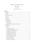
Technical Note
VR5 Dynamic Environment Emulation (DEE)
February 2013
79-002163, Version A0
Spirent
541 Industrial Way West
Eatontown, NJ 07724 USA
Email:
Web:
[email protected]
http://www.spirent.com
AMERICAS 1-800-SPIRENT • +1-818-676-2683 • [email protected]
EUROPE AND THE MIDDLE EAST +44 (0) 1293 767979 • [email protected]
ASIA AND THE PACIFIC +86-10-8518-2539 • [email protected]
Copyright
© 2013 Spirent. All Rights Reserved.
All of the company names and/or brand names and/or product names referred to in this document,
in particular, the name “Spirent” and its logo device, are either registered trademarks or trademarks
of Spirent plc and its subsidiaries, pending registration in accordance with relevant national laws.
All other registered trademarks or trademarks are the property of their respective owners.
The information contained in this document is subject to change without notice and does not
represent a commitment on the part of Spirent. The information in this document is believed to be
accurate and reliable; however, Spirent assumes no responsibility or liability for any errors or
inaccuracies that may appear in the document.
VR5 Dynamic Environment Emulation (DEE)
TABLE OF CONTENTS
Table of Contents .......................................................................................................... i
Scope ............................................................................................................................ 2
Channel DYNAMICS .................................................................................................. 3
DEE Features................................................................................................................ 5
DEE Specifications....................................................................................................... 6
Implementing DEE with the VR5 ................................................................................ 7
DEE For Handover Testing .......................................................................................... 9
DEE for MIMO Throughput vs. Correlation Testing ................................................. 11
RPI DEE ..................................................................................................................... 14
Summary and Conclusions ......................................................................................... 17
SPIRENT APPLICATION NOTES
•i
VR5 Dynamic Environment Emulation (DEE)
SCOPE
The information contained in this document is the property of Spirent. Except as expressly authorized in
writing by Spirent, the holder shall keep all information contained herein confidential, shall disclose the
information only to its employees with a need to know, and shall protect the information from disclosure
and dissemination to third parties. Except as expressly authorized in writing by Spirent, the holder is
granted no rights to use the information contained herein. If you have received this document in error,
please notify the sender and destroy it immediately.
SPIRENT APPLICATION NOTES
•2
VR5 Dynamic Environment Emulation (DEE)
CHANNEL DYNAMICS
Suppose a user lives in suburban area. Every morning he walks to the train station and rides into a city.
He then walks through the city to his office as he watches morning news video streams during his
commute.
Figure 1 – Different Channel Propagation Scenarios.
In this example, the mobile station (MS) experiences a variety of different channel scenarios. These
include pedestrian and vehicular speeds in a suburban area, followed by a pedestrian scenario in an urban
environment. These different scenarios have unique radio channel characteristics that may be favorable or
adverse to the desired application (voice, real-time video streaming, web browsing, etc.).
In general, the radio channel is described by channel models often pre-defined to represent a particular
environment type or use scenario. For instance, these pre-defined models may include the ITU PedestrianB and Vehicular-A models that are common.
These models specify the number of delay taps, their relative powers, and specify a classical Doppler
assumption for the fading behavior at predefined speeds, spatial correlation (in case of MIMO). Many
other models exist, and engineers often modify these models or create new ones for particular purposes.
To model the Channel Dynamics of a MS moving through the various environments represented by this
example, several different channel models are defined in the DEE to represent the characteristics
observed in each environment.
The channel dynamics can be characterized in time, spatial, and frequency domains. When the mobile
speed is low, channel variation is slow and Doppler spread is small, corresponding to large channel
coherence time. Due to the change of location, the number, relative power, and delay of RF paths
presented at the mobile station vary. This results in a change of delay spread because suburban areas
typically have larger delay spread than urban areas. The change of delay spread causes a change in the
channel coherence bandwidth. This may have a significant effect on performance, because OFDM-based
technologies are especially sensitive to coherence bandwidth; unless mitigation techniques, such as
frequency selective scheduling are employed. Another obvious variation is in the received power. Power
fluctuation results in variation of the signal-to-noise ratio (SNR). Also, environments can be characterized
in the spatial domain, where multipath richness changes the spatial correlation seen at the MS and BS
antennas, and this affects the performance of the particular MISO, SIMO, MIMO technique being used,
from simple receive diversity to beamforming, to spatial multiplexing.
SPIRENT APPLICATION NOTES
•3
VR5 Dynamic Environment Emulation (DEE)
Different channel coherence time and bandwidth, and spatial correlation have different impacts on system
performance; they are key design parameters for link adaptation algorithms. With dynamic channel
emulation, test engineers can evaluate the end user’s experience in these typical scenarios.
Another application of dynamic channel emulation is to verify link adaptation algorithms that explore the
channel in time, space, and frequency domains. To test the limits of the algorithm, it is essential to have
full control of the coherence time and bandwidth of the channel, or the Doppler and delay spread, or the
spatial correlation.
SPIRENT APPLICATION NOTES
•4
DEE FEATURES
As explained before, DEE allows the dynamic change in propagation conditions at specified time
intervals. The following parameters can be changed:
• Output Port Settings
• Output Power
• AWGN Status (ON/OFF)
• C/N Ratio
• Propagation Condition Settings
• Path Status (ON/OFF)
• Path Delay
• Relative Path Loss
• Rician Line of Sight Angle of Arrival
• Rician K Factor
• Frequency Shift
• Doppler Velocity
• MIMO Radio Links
• MIMO Radio Link Status (ON/OFF)
• MIMO Radio Link Relative Power
• MIMO Radio Link Phase
• Correlation
DEE is only available when the Fading Mode is set to “Classical Channel Models.”
The unique advantages of DEE in modeling the channel dynamics are:
• Full control of delay spread and Doppler spread.
• Full control of spatial correlation for SIMO, MISO, and MIMO Techniques.
• Change of mobile velocity.
• Long time simulation.
• Full dynamic range of received signal power.
• Multi-cell simulation.
• Mapping Channel Dynamics into DEE.
To utilize the unique advantages of DEE, the following sections provide information on how to map the
example scenario into the states of DEE in the VR5.
DEE SPECIFICATIONS
• Maximum State Transition Time:
• 400 μs (Measured from start of state change to completion of state change)
• DEE Trigger Characteristics:
Trigger Signal TTL, Rising Edge
Trigger Signal Power 3.3 V
Minimum Trigger Width 90 ns
Trigger Delay - from Trigger to
Change in Output Level < 5.0 ms
Change in other parameters < 1.0 ms
IMPLEMENTING DEE WITH THE VR5
The first thing is to check that the license is enabled. Please go to Help->Instrument Options, there verify
that the feature called Dynamic Environment Emulation is present as shown below:
Figure 2 DEE license verification.
Before discussing the DEE, it is necessary to set all the parameters that are not changeable by DEE. That
is, parameters that stay the same for the duration of the DEE operation. Any parameter not listed on the
DEE features above cannot be changed by DEE, and therefore it needs to be set either using the GUI or
through RPI commands. Notable among those parameters are the center frequency, the fading type
associated with each path, and the connection setup.
Then, a new DEE template needs to be open. The template can be open by going to the DEE->New
Emulation File menu on the VR5 front panel, as shown in Figure 3.
A new DEE template file that looks like the one shown in Figure 4 opens. Notice that the connection
setup matches that shown in Figure 3; however, if this connection setup is not the desired one, this can be
changed directly in the DEE template by clicking on the connection setup drop-down menu.
The emulation file can be modified using standard Excel methods. The emulation file contains the
following tabs: Main, ChProp (one per independent connection, in this example four), RLINK, and
Correlation (one per independent connection, in this example four). For the exact description of each tab
please refer to the VR5 User’s manual.
Figure 3 Invoking a New Emulation File.
Figure 4 New DEE Template.
DEE FOR HANDOVER TESTING
Handover is an important aspect of mobility support for all wireless based technologies. As the user
moves around, the strength of the received signal at the Mobile Station (MS) from the different Base
Stations (BS) varies. Handover is carried out when certain thresholds or requirements in the received
signal are met. The cell measurements at the MS are the basis for the decision making in the handover
algorithms.
For this example assume that two 2x2 MIMO cells operating at different frequencies are received by the
MS. At first the power output from cell 1 is set to a high value, whereas the output from cell 2 is set to a
low value so the MS camps in cell 1, then, the DEE engine is set to decrease the power of cell 1 at a rate
of 2dB/s and to increase the power of cell 2 at a rate of 2dB/s as shown in Figure 5 (fast fading was
averaged out for clarity). The resulting DEE template file is shown in Figure 6. There will be a time in
which the handover mechanism is triggered by the difference in the received powers. You can easily
define the rate of change of the cell power and the power level of each cell according to the test
requirements.
-30
Cell 1
Cell 2
-40
Received power dBm
-50
-60
-70
-80
-90
-100
30
35
40
45
time
50
55
60
Figure 5 Variation of Cell Power Emulated by DEE for Handover Testing
The received cell power at the MS from the two base stations is controlled through DEE to emulate
variations of path loss due to change of position. This test setup can be modified according to the
requirements of different standards. It can also be easily extended to test handover under other more
complex conditions; such as the presence of AWGN and/or with different fading profiles.
Figure 6 DEE template file for the Handover example
From Figure 6, we note that the state duration is 0.5 seconds, and each state changes both B1 and B2 (for
cell 1) and B3 and B4 (for cell 2) by 1dB, giving the overall change rate of 2dB/s. As mentioned before,
this can change to whatever a particular test needs.
DEE FOR MIMO THROUGHPUT vs. CORRELATION TESTING
One of the fundamental parameters that affects MIMO throughput is correlation at both ends, that is,
transmit and receive correlations. DEE allows changing dynamically the correlation seen at the
transmitter and receiver. For this example, we use an LTE 2x2 MIMO open-loop spatial multiplexing
technique. For the entire emulation period, the same propagation channel is used, namely, LTE EPA5 (see
Figure 7), but the correlation matrix used changes from low correlation, to medium correlation, to low
correlation to high correlation (see Figure 11).
Figure 7 LTE EPA5 Channel model
Then, the throughput vs. time is recorded and the change in throughput when the correlation is changed is
presented in Figure 8. It is interesting to note the impact of the correlation on throughput. At time 11s, the
correlation changes from low to medium, and the throughput changes from 71Mbps to an average of
36Mbps, that is a reduction of 50%. The impact is even more dramatic at time 37 seconds where the
correlation changes from low to high, and the throughput changes to an average of 1.6Mbps or a
reduction of 98%.
LTE Data Throughput vs. Correlation
80000
Throughput kbps
70000
60000
50000
40000
30000
20000
10000
0
0
10000
20000
30000
40000
50000
Tine ms
Figure 8 Throughput vs. correlation
The DEE template file main tab is shown in Figure 9. Notice that the output power is fixed for the
duration of the dynamic emulation. Also, the channel propagation is fixed to LTE EPA5 as shown in
Figure 10.
Figure 9 DEE template file main tab
Figure 10 DEE template file channel propagation 1 tab
Finally, each correlation matrix is changed after 30 seconds as shown in Figure 11.
Figure 11 DEE template file Correlation 1 tab
RPI DEE
So far, all the DEE operations have been shown via GUI. The VR5 provides the same functionality via
RPI to support fully automated setups. The following is a list of RPI commands related to DEE. Please
consult the VR5 user’s manual and the RPI command reference for more details.
[SYSTem]:DEE:[STATe]?
Query, Enable or disable DEE.
[SYSTem]:DEE:MODe?
Set the DEE Playback Mode to loop continuously, to loop once, or to loop a specific number of times.
[SYSTem]:DEE:TYPe?
Set or query the DEE Trigger Mode to Free Run, HW Triggered, or State Triggered.
[SYSTem]:DEE:CSTATe?
Query the current DEE state number.
[SYSTem]:DEE:CLOOP?
Query the current DEE loop number.
[SYSTem]:DEE:ETIMe?
Query the current DEE elapsed time.
[SYSTem]:DEE:NUMSTates?
Query the number of DEE states.
[SYSTem]:DEE:NUMLoops?
Set the number of loops to play DEE when DEE:MODe is set to NUMber.
[SYSTem]:DEE:COMPile:ABORt
Abort the DEE compile.
[SYSTem]:DEE:COMPile:BEGin
Begin a DEE compile.
[SYSTem]:DEE:COMPile:FILE?
Set and query the DEE emulation file for the given unit.
[SYSTem]:DEE:COMPile:STATus?
Query the DEE compile status.
Possible Responses:
• “Aborting”
• Abort command received, but not finished processing. “Aborted”
• Compile was aborted “Completed”
• Compile completed successfully “Failed”
• Compile Failed "Compiling”
• Compile in process, reported during initial compile, before individual unit compile begins
• “Compiling Unit X, Y% Complete”
• Compile in progress, specifies unit and % complete
• “Compiling Unit X: Complete”
• Compile in progress, reported when one unit is complete, but the next not yet begun.
[SYSTem]:DEE:PAUSE?
Pause DEE fading or query DEE pause state.
[SYSTem]:DEE:PAUSEOnstate
Pause DEE at a user specified state.
[SYSTem]:DEE:RESume
Resumes normal DEE operation if DEE is paused.
[SYSTem]:DEE:ADVance
Moves a DEE operation to the next state.
As an example, the following Ruby script connects to the VR5, points to the DEE file to compile (this
assumes
the
file
“Tput_vs_correlation.xstb”
already
exists
inside
the
VR5
at
d:\ftproot\spirent\VR5\DEE\), compiles that file, checks continuously for the compilation process to
terminate, sets the DEE state to on, plays the DEE file, and then disconnects.
SUMMARY AND CONCLUSIONS
Dynamic Environment Emulation is a powerful tool provided by the VR5. It allows the user to prescribe a
wide variety of changes in propagation conditions that are executed dynamically. This provides the user
with the capability of recreating very particular circumstances to test algorithms deep within devices,
protocols, system level RF engineering, etc.