1
Radiated Electrical Noise
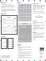
Wiring Table
• Ensure all equipment is properly grounded. (Motors, drives, shafts, etc.)
• Connect encoder cable shield to ground at controller/counter end, leaving the end near the
encoder unconnected.Connecting the shield at both ends can cause ground loops, and
improper operation.
• If possible, use differential line driver outputs with high quality shielded, twisted pair cable. (Complementary signals greatly reduce common mode noise levels, as well as signal distortion resulting from long cable lengths.)
Typical Electrical Hook-Ups
Erratic Output/Missing or Extra Counts
Function
Gland
Cable Wire
Color
5-pin
M12
8-pin
M12
Com
Black
3
7
F
+VDC
White
1
2
A
Brown
4
A’
Yellow
B
7-pin MS
OC
6-pin MS
10-pin
Bayonet
F
F
A,F
F
D
D
D
B
D
1
A
A
A
D
A
• Mechanical: Check for improper alignment or loose coupling. Counts indicate
wrong direction
—
3
H
C
—
—
H
• Check for reversed wiring of the quadrature signals. Reverse if needed.
Red
2
4
B
B
B
E
B
• If differential signals are being used, make sure both sides are properly wired.
B’
Green
—
5
I
E
—
—
J
Z
Orange
5
6
C
—
C
C
C
Z’
Blue
—
8
J
—
—
—
K
Case
—
—
—
G
G
G
—
G
Shield
Bare
—
—
—
—
—
—
—
10-pin MS 7-pin MS
LD
Note
If an index pulse is being used, reversing the wiring
will cause the reference alignment to change.
Counts In Only One Direction
• Make sure the counter/controller is capable of, and programmed for,
bi-directional counting.
Encoder Connector Cable Assembly Wiring
STANDARD
FUNCTION
Output Circuit Diagrams
10 PIN
MS
7 PIN MS
TWISTED PAIR
6 PIN MS
12 PIN
• Electrical: Check for loose wiring connections, ground loops, encoder outputs
incompatible with the counter/controller, a noisy power supply, electrical noise,
proper termination of shields, or a combination of these problems.
M12 CORDSET
10 PIN
MS
7 PIN
MS
6 PIN
MS
8 PIN
5 PIN
LD
OC
LD
LD
OC
LD
OC
LD
OC
LD
LD
LD
COM
Black
Black
Black
Black
Black
Black
Black
Black
Black
Black
Blue
Blue
+VDC
Red
Red
Red
Red
Red
Red
Red
Red
Red
Red
Brown
Brown
A
White
White
White
Orange
White
White
White
White
White
White
White
Black
A’
Brown
Brown
----
White
----
Brown
----
Black
Black
Black
Green
----
B
Blue
Blue
Blue
Green
Green
Blue
Blue
Blue
Blue
Blue
Yellow
White
B’
Violet
Violet
----
Blue
----
Violet
----
Black
Black
Black
Gray
----
Z
Orange
----
Orange
----
Orange
Orange
Orange
Yellow
----
----
Pink
Gray
Z’
Yellow
----
----
----
----
Yellow
----
Black
----
----
Red
----
Case
Green
Green
Green
----
----
Green
Green
Green
Green
----
Bare*
Bare*
Shield
Bare
Bare
Bare
Bare
Bare
Bare
Bare
Bare
Bare
Bare
Bare
Bare
Com Sense
----
----
----
----
----
Gray
Gray
----
----
----
----
----
+VDC
Sense
----
----
----
----
----
Pink
Pink
----
----
----
----
----
• On quadrature units, both channels (A and B) must be present and operational.
Check by using a dual channel oscilloscope.
• Make sure the input selection type programmed into the counter/controller,
matches the Timken THS25. If there is a mis-match, the system may not
work properly.
Index Pulse Not Working
• The index pulse occurs only once per revolution, and can be difficult to check
with a volt meter. Check index pulses with an oscilloscope.
• The counter/controller may not be capable of detecting the index pulse at
higher RPM’s. Slowing down the rotation may allow for detection of the
index pulse.
• Verify wiring.
*Only on specified cordsets
Troubleshooting
No Output/No Counts
Open Collector
Line Driver
Every reasonable effort has been made to ensure the accuracy
of the information contained in this writing, but no liability is
accepted for errors, omissions or for any other reason.
661_Encoder Instruct Sht.indd 2
• If there is no mechanical movement, there will be no output. Therefore, verify that the
Timken THS25 is rotating.
• Check to make sure the proper supply voltage is present. It is best to do this at the Timken THS25 end, if possible.
• Verify all wiring between the Timken THS25, the counter/controller, and the power supply.
www.timken.com
• Make sure the proper signal type (OC, LD) is being used for the application.
Timken® is a registered trademark of
The Timken Company
• Verify the counter/controller is properly installed and operational. Consult the appropriate
counter/controller User’s Manual if necessary.
• If another Timken THS25 is available, try it to determine if the encoder is the problem.
© 2009 The Timken Company
Printed in U.S.A.
5M 07-09-29 Project No. 0661
7/14/09 3:21:02 PM