1
The Innovation Behind Broadband Wireless
IP-based
Broadband Wireless Access (BWA) System
605-0000-845 Rev E
Netspan
Release 6.5
User Manual
Connecting the World
Table of Contents
What's New ............................................................................................................................. 5
Installation ............................................................................................................................. 13
Server Installation ................................................................................................................ 17
Server Upgrade .................................................................................................................... 54
NMS Server Management.......................................................................................................... 57
Getting Started ....................................................................................................................... 67
Main ...................................................................................................................................... 85
Configuration Management ....................................................................................................... 95
Subscriber Provisioning .......................................................................................................... 95
Subscriber Station .............................................................................................................. 100
Subscriber Station Management ............................................................................................ 105
Remote Management ........................................................................................................ 120
Multiple Subscriber Station Management ................................................................................ 175
BS TRx .............................................................................................................................. 185
BS TRx Management ........................................................................................................ 196
Configure Software Download ............................................................................................ 210
Multiple BS TRx Management ............................................................................................. 218
BS TRx Channels ................................................................................................................ 231
BS TRx Channel Management ............................................................................................ 237
Multiple BS TRx Channel Management ................................................................................. 252
BS TRx Inventory................................................................................................................ 259
SS Inventory ...................................................................................................................... 260
Shelf ................................................................................................................................. 261
Manage Shelf .................................................................................................................. 264
BSDU ................................................................................................................................ 271
Manage BSDU.................................................................................................................. 275
Global SS Provisioning ......................................................................................................... 284
Topology .............................................................................................................................. 285
Service Profiles ..................................................................................................................... 291
Service Products ................................................................................................................. 292
Service Classes................................................................................................................... 298
Packet Classifier ................................................................................................................. 303
VLAN ................................................................................................................................ 309
SS Custom Configurations .................................................................................................... 312
SS VLAN Port ..................................................................................................................... 315
BS TRx Profiles ...................................................................................................................... 319
Software Management............................................................................................................ 347
Software Upgrade ............................................................................................................... 360
Fault Management ................................................................................................................. 369
Performance Management....................................................................................................... 385
Server ................................................................................................................................. 397
iii
Netspan Release 6.5
Discovery Parameters .......................................................................................................... 397
Server Global Configuration .................................................................................................. 400
Trap Destinations................................................................................................................ 402
Users ................................................................................................................................ 403
Filters ............................................................................................................................... 407
Export ............................................................................................................................... 412
Import .............................................................................................................................. 413
IP Network......................................................................................................................... 414
Reports ................................................................................................................................ 417
Backup and Restore ............................................................................................................... 421
Appendix .............................................................................................................................. 423
General ................................................................................................................................ 465
Glossary ............................................................................................................................... 469
iv
Introduction
This manual covers the use of the Netspan Network Management System (NMS). The fields of each
screen are described along with processes for setting up/editing ASMAX BS TRx and SS equipment.
Note: Some screens captured in this manual may be cosmetically different dependant on the build
deployed.
Terminology
BS TRx refers to the Base Station Transceiver. This was referred to as a base station in earlier
documents but has now been changed to avoid confusion with other definitions of base station.
Definition: The entity with single management stack. It consists of one or more BS TRx Channels
BS TRx Channel refers to the radio channel within the spectrum. In earlier documentation this was
often referred to as a sector. Definition: The entity representing a single 802.16 MAC+Phy interface as
defined in 802.16-2-004 standard
SS refers to a subscriber station. Often referred to as CPE (Customer Premise Equipment). The Airspan
version is referred to a an ST (Subscriber Terminal) i.e. EasyST and ProST.
VoiceMAX is Airspans offering of VoIP (Voice Over IP) on MicroMAX equipment.
Structure
The Manual is organised into the following sections:
Network Management Overview: Describes some of the basic concepts behind a Netspan NMS
Installation: Describes the installation of database, sever and client machines
Getting Started: Describes the User Interface, account management and basic configuration steps.
Search: Instructions for using the search facility in Netspan
Configuration Management: Configuration, status and inventory management for all supported
network elements.
Topology: Setting up regions and sites
Service Profiles: When creating an SS, properties of that SS are assigned properties through Service
Products, Service Classes, Packet Classifiers, VLAN
BS TRx Profiles: When creating an BS TRx, properties of that BS TRx are assigned properties through
Burst Profiles, OFDM Channel Profiles, 802.16 Protocols, Private Key Management, Subchannelisation,
Custom Configuration and VoIP QoS profile.
Server: Contains information on server management, security and filters.
Software Management: Software download to BS TRx and SSs.
Fault Management: Alarm and Event Management
Performance Management: BS TRx Ethernet Stats, BS TRx Air Interface Stats, SS RF Stats, SS
Modulation Stats, SS Packet Counts.
Reports: System status reports
Backup and Restore: System restoration and database backup procedures.
Appendix: Supporting information.
New users should start with the Getting Started section to familiarize themselves with the interface and
basic setup procedures.
Note: Netspan is designed to manage all 802.16-2004 WiMAX compliant equipment. The term
SS is used to describe subscriber stations in general. Netspan uses the term ST( EasyST and
ProST) to refer to Airspan WiMAX compliant SS's and for the purposes of this manual the terms ST
and SS are interchangeable.
Netspan is a WEB based client-server Network Management System. Netspan server runs on a Windows
2003 Server PC(s) equipped with SQL server software. The server connects to the ASMAX equipment
1
Netspan Release 6.5
shelf. Netspan client runs on a Windows PC with Internet Explorer . Client PCs are connected to the
server over an IP link.
Netspan is a client-server application, with 'always-on' server components implemented as windows
services, and with a front end web intranet application. Netspan uses SNMP over Ethernet to
communicate with ASMAX equipment.
Key features :
o
Fault management with comprehensive event, active alarm and historical alarms system
o
Configuration management with provisioning, configuration, status tracking and reporting,
software upgrade and inventory management for BS TRxs, Subscriber Stations and other
associated network elements
o
Performance management with collection of wide range of historical statistical data
o
Security management with NMS authentication and authorisation as well as with secure SNMP
communication to equipment
Characteristics of Netspan for ASMAX:
o
Support for both nomadic and fixed SS
o
802.16d (802.16-2004 standard) SS is configured for service on the network. Does not have to
be tied to a fixed BS TRx, (although can be).
o
SQL database engine for Netspan database
o
Indirect management of SS (MIB model)
o
Template/class based provisioning
o
Asynchronous configuration for provisioning data
o
Synchronous configuration for commissioning data
o
Asynchronous status and statistics collection
o
Full off-line provisioning capabilities
o
Database is a master for provisioning data
o
Re-synchronisation between equipment and NMS on request.
The Netspan server is accessed using upper level WEB browser (recommended Internet Explorer v6 or
later), with BS TRx and Subscriber Station (BS TRx and SS) provisioning, management and faulthandling being accessed via web-based pages.
An SQL database is used to store all the provisioning information, alarms, events and statistical
information.
The web browsers clients are normally remote from the server machine but it can be arranged to run
both the client and server on one machine if required.
Netspan uses a management information base that can be monitored by a network management
system. The management information base is used by SNMP, which allows monitoring of equipment
within the ASMAX product range. The three MIBs are identified as follows:
o
802.16f standard MIB
o
BS TRx private MIB (developed by Airspan)
o
SS private MIB (developed by Airspan)
The private MIBs contain features that are important for the management of the radio network but
which are not defined within the standard 802.16f MIB.
Netspan Components
3rd Party Server Components:
o IIS - Microsoft Standard
o
.NET Framework - Microsoft Standard
o
SQL Server Database - Microsoft
o
NetToolWorks SNMP Manager Library
Netspan Server Components (developed by Airspan):
2
Introduction
o
Front end ASP.NET web intranet application
o
SNMP job engine service
o
Discovery service
o
Alarm Service
o
Archive Service
o
Event Service
o
Software Manager Service
o
Provisioning Service
o
Statistics Service
ASMAX Management
ASMAX products are managed by Netspan. A shelf is managed using an IP based protocol for
connection over a network using an Ethernet interface.
Configuration of Netspan is through the management system as are alarms, performance and statistics.
Netspan has the capability of simultaneously managing up to 5000 BS TRxs and 200,000 subscribers.
Database
The Netspan database is the master for provisioning data, whereas ASMAX equipment contains the
master database for status and statistics.
The SQL database stores the following items:
o
Alarms
o
Events
o
Topology information
o
Provisioning data
o
Statistics data
o
Inventory data
SNMP Support
o
Netspan integrates the SNMP libraries and provide internal access interfaces.
o
Netspan sends trap for each alarm of each type defined for the AS.MAX system
o
Netspan allows traps to enable/disable traps for each alarm type independently
o
It is NOT be possible to enable/disable different alarm types for different shelves but database
format should allow this extension in the future
Alarms
All of the systems alarms are sent to and acknowledged by the management system. The management
system allows visibility of all alarms, and provides navigation and support to identify the cause of the
alarm. The management system also provides logging of alarms in the database.
Statistics
System statistics and status are all collected by the management system at programmable intervals.
Statistics and status information will be lost in the case of system power failure.
The management system presents the data in tables. All of the data can be logged to file, which can be
stored on the hard disk.
All statistics are time-stamped.
3
Netspan Release 6.5
Important Definitions
Template / Profile
"template" and "profile" are terms used in the document in places referring to the same entity defined
as a "Set of properties grouped and identified by the name, used to provision/configure
equipment/service by simple reference to the name of the template/profile (e.g. Packet Classifier Rule
Profile). Profiles/templates are stored in the Netspan database and are applied to the equipment as a flat
set of properties."
Class
A Class is a set of properties grouped and identified by the name for the common use in the Netspan
database and BS TRx database (e.g. Service Class). Since the definition of the class is known by BS TRx
the configuration is simplified to setting only class name instead of flat set of all properties.
4
What's New
What's New Release 6.5
Frequency Bands
Generic Netspan support for all the new frequency bands introduced in this release.
Configuration of NTP Servers
Each BS TRx can be assigned up to four NTP server IP addresses, which can be used for time
synchronisation. It is possible to configure those IP addresses from Netspan (instead of using the direct
Web browser of the BS TRx). This feature is not available for MicroMAXBS TRx.
Configuration For Q-in-Q Mode
The IEEE 802.1Q-in-Q VLAN Tag is purpose to expand the VLAN space by tagging the tagged packets,
thus producing a "double-tagged" frame. The expanded VLAN space allows the provision certain
services, such as Internet access on specific VLANs for specific customers, and yet still allows the service
provider to provide other types of services for their other customers on other VLANs. Generally the
service provider's customers require a range of VLANs to handle multiple applications. Customers can
use this feature to safely assign their own VLAN IDs on subinterfaces because these subinterface VLAN
IDs are encapsulated within a service provider-designated VLAN ID for that customer. Therefore there is
no overlap of VLAN IDs among customers, nor does traffic from different customers become mixed.
Reuse Group
When adjacent sectors share the same channel different reuse groups are set for each sector. SSs that
can see both sectors will only sign on to one sector. Reuse groups can be disabled or set to either Group
A or Group B.
Support For New MicroMAX Features
o
Clearest Channel Choice (CCC), BS TRx Netspan CCC configuration support has been added.
o
Subchannelisation is now supported by MicroMAX BS TRx and enabled in Netspan.
o
Scheduler defines scheduling, priority or WFQ. Netspan introduces an extra property in BS TRx
custom config table to support this feature.
o
MAC Forced Forwarding is now available on MicroMAX As already available as part of VLAN
configuration in MacroMAX and HiperMAX. With MAC Forced Forwarding the BS is given the IP
address of the traffic gateway (Router), and it learns the MAC address of the gateway. ARPs in
the uplink direction are not forwarded out of the BS, instead the BS replies to the ARP, giving
the MAC address of the gateway.
Northbound Interface
o
New Fault Management web service to supports
o
Retrieval of active alarms
Allow acknowledge and editing of alarms.
Create/edit extensions to the service flow template and related items (e.g. classifier
templates).
Features of Release 6.0 that are also in 6.5
Change of Terminology
For release 6.0 the term 'Base Station' when it refers to hardware has been renamed BS TRx (Base
Station Transceiver). This was renamed as base station has a broad range of meanings whereas BS TRx
is specific to the actual transceiver (HiperMAX Blade HiperMAX-micro SDR and SCRT, MacroMAX and
MicroMAX.
The term 'Sector' has been replaced with 'Channel' to bring it more in line with standard industry
terminology.
Note about the installation
5
Netspan Release 6.5
Netspan server should be installed on dedicated server machine. The configuration where Netspan
shares hardware with other server application (e.g. web sites) is not supported.
The only allowed OS platforms Netspan can be installed on are: Windows 2003 and Windows XP
Pro. The installation program in SR6.0 enforces this requirement and stops installation if not
supported an unsupported OS is detected. Older versions of Netspan were less strict and allowed
installation on other OS platforms such as Windows 2000 Server. The upgrade of OS from Windows
2000 to Windows 2003 to satisfy the Netspan installation program may lead to some security issues
and is not recommended. We recommend only new installations of Windows 2003 and Windows XP
Pro and not upgrades from older systems.
Northbound Interface
The Netspan northbound interface supports communication between the Web Service client or
consumer and Web Service server or Provider (hosted by Netspan), and is achieved via the
exchange of SOAP (Simple Object Access Protocol) messages over HTTP. The services exposed by
the Web Service are defined using WSDL (Web Service Description Language) files, which specify
the contract between the client and server facilitating the easy development of Web service clients
using most major programming languages / operating systems. The initial release of the Netspan
Northbound interface concentrated on SS Provisioning. This service allows the provisioning of SSs
and also the execution of a number of other standard operations related to SS Provisioning e.g.
Enabling or Disabling service on an SS.
This release provides
o
New WEB services for definition of service profiles. This extension is exclusively offered to a
single customer.
o
Multiple trap destination support covering BS TRx and BSDU. This feature allows customers with
third party fault management system (e.g. HP OpenView) to quickly configure up to 8 trap
destinations (including one for Netspan) on all BS TRxs and BSDUs in the network.
Statistics
Several new categories of statistics are available in SR6.0
o
o
BS TRx Air Interface Stats has been divided into two separate categories as follows:
BS TRx Interface Usage. These are the per interface frame usage statistics that
were previously available.
BS TRx Air Interface Counts. These are per interface counters. They include the
Broadcast SDU and Broadcast Octet Counts that were available previously as well
as new counters for SR6.0 covering management and traffic SDUs and octets for
both uplink and downlink directions.
SS Ethernet Stats
These are new for SR6.0 and report the SS Ethernet Stats per SS as measured on the SS
and reported to theBS TRx.
o
SS Air Interface Stats
These are new for SR6.0 and report the SS Air Interface Counts per SS as measured on the
SS and reported to the BS TRx. The counters cover management and traffic SDUs and
octets for both uplink and downlink directions.
The statistics are available on the management pages as follows:
Single and multi BS TRx management:
6
BS TRx Ethernet Statistics - full history.
BS TRx Air Interface Usage - latest measurements only.
BS TRx Air Interface Counts - latest measurements only.
SS Ethernet Statistics - latest measurements only.
SS Air Interface Statistics - latest measurements only.
SS RF Statistics - latest measurements only.
SS Modulation Statistics - latest measurements only.
SS Packet Counts - latest measurements only.
What's New
Single and multi Channel management:
BS TRx Air Interface Usage - full history.
BS TRx Air Interface Counts - full history.
SS RF Statistics - latest measurements only.
SS Modulation Statistics - latest measurements only.
Single and multi SS managements:
SS Ethernet Statistics - full history.
SS Air Interface Statistics - full history.
SS RF Statistics - full history.
SS Modulation Statistics - full history.
SS Packet Counts - full history.
MicroMAX BS TRxs will support a subset of these statistics in SR6.0
It is possible to navigate to the management page of any BS TRx, Channel or SS in the statistics
grids by following the appropriate hyperlink in the grid.
Integrated VLAN provisioning
o
MacroMAX/HiperMAX/HiperMAX-micro support for PVID.
Release SR6 brings the implementation of VLAN bridging closer to IEEE802.1Q
standard. SR6 MacroMAX, HiperMAX and HiperMAX-micro SR6 now have standard
implementation of Port VLAN ID and accepts standard based configuration with
Acceptable Frame Types and PVID.
The backwards compatibility is guaranteed in both directions:
BS TRx running SR6 code still responds to old configuration sets.
Netspan running SR6 offers the support for both legacy and 802.1Q based
configuration (auto-detection of the support).
Netspan has new set of warning messages reflecting the changes in the configuration
system and depending on the support available in a given BS TRx.
o
o
Protocol VLANs
Classifier based VLAN tagging.
VoiceMAX dynamic service flow VLAN tagging (MicroMAX)
Bridging section in custom configuration (platform dependent):
Ageing time (all platforms).
LAN table size per BS TRx (MacroMAX, HiperMAX and HiperMAX-micro).
Flooding control (MacroMAX , HiperMAX and HiperMAX-micro).
The use of custom configuration profile for some bridging properties will help customers in
turning new bridging generic properties on for the entire population of the BS TRxs.
The basic bridge and port configuration remains on the BS TRx edit page and is not covered
by the multi configuration. The future releases will see all the BS TRx bridge and port
configuration transferred to a new BS TRx bridging profile for more flexibility.
o
DHCP option 82 for each VLAN for all BS TRx platforms. New binary mode.
o
Support for default priority used for frames tagged with Port VLAN ID.
Support for MicroMAX
In addition to statistics, VLAN support changes and SS management support the following new
features are available in SR6.0.
o
Dynamic Frequency Switching:
7
Netspan Release 6.5
Configuration with new BS TRx Channel profile "Unlicensed Channel Profile”
(MicroMAX platform only).
New event (trap) reporting DFS changes and failures. New associated alarm. (see
full list of new events at the end of this document)
DFS feature is not available on all MicroMAX BS TRx. Only BS TRx with DFS
feature supported and enabled will process the configuration done with
"Unlicensed Channel Profile”. Other BS TRxs will ignore the sets.
o
o
o
Custom Configuration Profile: New BS TRx Custom Configuration Profile properties for
MicroMAX platform:
Midamble Repetition Interval
New bandwidth 2.75 MHz
Bridge Ageing Time
Ofdm Channel Profile: Existing BS TRx Ofdm Channel Profile properties with extended support
in MicroMAX:
Frame durations
Cyclic Prefix
Service Class: Existing Service Class properties with extended support in MicroMAX:
o
Scheduling Type: rtPC, UGS
VoiceMAX: Support for VoiceMAX in MicroMAX via BS TRx VoIP QoS Profile.
Support for MacroMAX, HiperMAX and HiperMAX-micro
MacroMAX, HiperMAX and HiperMAX-micro support for new features as described in other sections:
o
Statistics
o
VLAN support changes
o
SS management support
SS new features
o
Changes to SS Custom Configuration Profile:
New downlink adaptive modulation configuration (averaging factors, SNR margins)
New limit to maximum number of network hosts
o
New event (trap) indicating the change of any of identification parameters (addresses, versions)
as described above.
o
It is possible to restrict the list of BS TRx Channels on which an SS may register. SS
provisioning now allows the assignment of 'Service' allowed channel and 'Registration' allowed
channels.
o
SS global service provisioning is available under Configuration Management, allowing a
combination of service parameters (service product, configuration template and VLAN template)
to be assigned globally to all SSs, on a network wide basis.
o
SS reporting inventory and equipment addresses.
SS reports to BS TRx, using custom management messages the following: its own IP
address, SW version and HW revision number, MAC Address and IP address of integrated
WiFi AP and MAC Address and IP Address of integrated voice gateway (EasyVoice).
BS TRx exposes reported values in read-only MIB table and also sends the trap when any of
the values change for any given SS.
Netspan reads the values from the BS TRx MIB table and also from the objects of the
relevant trap and displays the values on the screen.
IP Addresses are displayed as HTML links to local management pages of the corresponding
equipment.
WiFi AP management
8
What's New
o
The SS list now contains additional columns for WiFi access point and residential voice gateway
IP addresses.
o
The SS inventory list has additional columns for the WiFi access point and residential voice
gateway Mac Addresses.
o
The SS management page State tab now has the additional information of WiFi Access point and
residential voice gateway IP and Mac addresses.
o
A new event type ("SS Equipment Status Change”) has also been added for the trap containing
the WiFi and easy voice IP and Mac addresses.
BSDU management
o
o
o
Provisioning
provides identity, SNMP connection and port connection information.
Port connections are automatically discovered if the BSDU is capable of reporting
them.
In a scenario where BSDU loses connection with MicroMAX, last port connection
information is maintained in Netspan. (BSDU expires port connection information in
3 minutes.)
In a scenario where a MicroMAX is moved from a BSDU to a Site by a user, port
connection information should also be manually released.
In a scenario where a MicroMAX which is connected to a BSDU is replaced with
another, the old MicroMAX could be found under the same site as of the BSDU.
provides connection state, provisioning state and facility to re-provision BSDU.
State
Software
o
o
o
provides means to upgrade and monitor software status of BSDU.
Inventory
provides available inventory information of BSDU.
provides alarms synthesised from Netspan events.
This includes snmp connection state alarms, port connection state alarms, port
power state alarms, link alarms and GPS alarms.
Events synthesised from BSDU traps as well as Netspan internal events.
This includes snmp connection state events, port connection state traps, port power
state traps, link traps and GPS traps.
Alarms
Events
ATCA hardware management
ATCA shelves are now discovered by Netspan via discovery of either the Shelf Manager via SNMP or
information provided by the HiperMAX and HiperMAX-micro SDRs contained within the ATCA shelf.
A new discovery type "Shelf" has been added to the list of discovery types to enable the discovery
parameters to be specified for Shelf Managers.
A new "Shelf" list page is available under "Configuration Management" giving access to "Edit" and
"Manage" pages for a single Shelf.
Shelf Management:
o
Provisioning: Identity and SNMP connection information
o
Slot: Details of each slot in the Shelf such as whether a board is present and the board type
o
Alarms: Alarms based on Netspan events.
o
Events: Events based on Netspan internal conditions.
9
Netspan Release 6.5
Topology
o
Topology changes
The topology hierarchy has been updated to recognise that:
1) HiperMAX BS TRxs are grouped together in Shelves
2) MicroMAX BS TRxs are grouped together by sharing a BSDU
A Shelf list page has been introduced and shelves may be added, deleted and have their
properties edited. The relationship between BS TRxs and Shelves is automatically
determined by the discovery service.
o
Topology Navigation Tree
The Topology Navigation Tree is a new view showing the hierarchy of items managed by
Netspan and provides the following features:
o
Integrated search of Names and Ids as they appear in the tree.
Layout is remembered so that the same items are shown next time the page is
visited.
Hyperlinks provide navigation to the management page or property page of each
item.
Icons show items that are unmanaged, are offline or have alarms associated with
them.
Additional information such as the IP Address is available in tooltips.
Management Page Mini Tree
The Mini Tree has been updated to provide the following new features:
Shelf and BSDU is shown in the hierarchy when present
It is possible to navigate down the hierarchy if a "+” button is shown. This gives
the next level in the hierarchy and provides links to the appropriate management
page.
Software Upgrade
o
Introduction of ‟r;Download and Activate‟ command for BS TRx, SS and BSDU.
o
As a consequence of this, the status of ‟r;pending‟, ‟r;in progress‟, ‟r;completed‟, and ‟r;retrying‟
for this command are reported in ‟r;Upgrade categories list‟ page and ‟r;Edit upgrade category‟
page.
o
Additional column introduced in software compact report to report ‟r;retrying‟ state separately.
o
Additional row introduced in software compact report to report on BSDU.
o
Scheduling available in node specific management page, multi node management page and
software category pages.
Password Security
o
Improved Netspan password security with configurable security policy. User can select one of 3
policies: Basic, Medium and High
Basic Security Policy is defined by what is implemented in Netspan SR5. This is a
default policy.
Medium Security Policy applies stricter rules on what strings are acceptable for
password, eliminates obvious strings like "password”, "pass” and enforces
password change of first login of a new user.
High Security Policy, in addition to Medium one, introduces strict password
recycling with configurable expiry period.
Miscellaneous
o
10
Use of AJAX technology
What's New
AJAX enables a web page to be partially updated without the need to fully reload the page.
It helps to eliminate the delay, flicker and loss of scrollbar position which can be seen when
pages communicate with the server without the use of AJAX.
Netspan makes use of AJAX to improve the user experience by giving a smoother, richer
experience for the user.
o
Global SS provisioning.
SS provisioning in SR5 was offered in form of single SS edit and multiple SS edit. The multiedit feature is limited to 100 SSs, which often is not enough for many users. On the other
hand the Service Product cannot be edit while in use. To address the need of changing
Service Product assigned to large number of SSs SR6 Netspan introduces Global SS
Provisioning Page.
The Global SS Provisioning page operation is similar to multi-edit but the selection of the
population of SSs to edit is performed based on the criteria given by user rather than by
selecting SSs on the list. The selection criteria choose SSs, which are provisioned with a
given set of profiles: Service Product, Custom Configuration and Port VLAN Profile.
The provisioning of large number of SSs is time demanding hence it is done asynchronously.
User can watch the progress on the page or go to a different page while the operation
continues.
o
o
Lists:
Export to Excel of entire list of items (SR5 offered only WYSIWYG list export)
Use 100% of available space
Custom sorting (IP address, enumeration backed columns)
Search has been added to list pages
Cleanup: removed not implemented actions:
Reset Channel (no channel actions available at all)
Delete SS Config (SS action)
Delete All SSs Config (BS TRx action)
Reinitialise MIB (BS TRx action)
o
During creation/edit of service products, it is now allowed to creates service flow templates with
identical parameters (except the service flow template name which needs to be unique within
the service product as was the case before).
o
SF Status added to Channel Management
SF Status is now available from the Channel Management page in addition to the BS TRx
Management and SS Management pages where is was previously available.
11
Installation
Installation Overview
This document describes the entire installation process. It is assumed that the reader is completely
familiar with all aspects of Windows Server 2003 administration - help on this is available in the
Windows 2003 documentation or on the MSDN, which is accessible from the Microsoft web site.
The only allowed OS platforms Netspan can be installed on are: Windows 2003 and Windows XP Pro. The
installation program in SR5.0 enforces this requirement and stops installation if an unsupported OS is
detected. Older versions of Netspan were less strict and allowed installation on other OS platforms such
as Windows 2000 Server. The upgrade of OS from Windows 2000 to Windows 2003 to satisfy the
Netspan installation program may lead to some security issues and is not recommended. We
recommend only new installations of Windows 2003 and Windows XP Pro and not upgrades from older
systems.
Netspan installation configurations:
o
Standard Netspan server installation. This is default installation configuration designed to offer
best performance for any size of the network up to 5000 BS TRxs and 200,000 SSs.
o
Small network Netspan installation. This is the installation for small networks, trials, training
and demonstration. It allows lower specification hardware and the software with more favorable
license terms. It is recommended for networks with less than 20 BS TRxs.
13
Netspan Release 6.5
Hardware Requirements
Netspan server should be installed on dedicated server machine. The configuration where Netspan
shares hardware with other server application (e.g. web sites) is not supported.
In normal operation, a separate server and client PC is required, although both can run on the same PC
if necessary. The server and client may be located remotely from the equipment being managed.
Host Requirements
For general use the following host machine is recommended for the server application:
o
CPU: Dual Processor (Pentium 4, Xeon or better with 1Mb L2 cache)
o
Memory: 2GB RAM
o
Drive Controller: Dual Channel Ultra 320 SCSI
o
RAID Controller: support RAID 01 or stripped mirror, e.g. PERC
o
Hard Drive: 2 x Hot Pluggable, 73GB, SCSI drives (15K RPM)
o
CD ROM Drive
o
Tape Back-up
o
Network Interface Card
For small network trials, where backup and redundancy capability within the host machine is not
required, the following specification can be used for the Netspan Server:
o
CPU: Pentium 4, 2.8Ghz
o
Memory: 1GB RAM
o
Hard Drive: 80GB
o
CD ROM Drive
o
Network Interface Card
Note: These are recommended minimum specifications
14
Installation
Software Requirements
The server is based around Internet Information services (IIS) See http://www.microsoft.com/iis. This is
a web hosting application, and allows the clients to connect up via HTTP using a standard web browser.
The web application is developed using Microsoft ASP.NET.
Note: Netspan server should be installed on dedicated server machine. The configuration
where Netspan shares hardware with other server application (e.g. web sites) is not supported.
Note: Netspan Requires an English version of OS, keyboard, SQL Server.
Note: Netspan must not be installed on a machine configured as a Domain Controller.
Installation of Netspan on a domain controller is not supported. Please install Netspan on a nondomain controller installation of Windows Server.
For general use the following host machine is recommended for the server application:
o
o
o
o
Server Operating System:
Windows 2003 server with the latest service packs. The installation pack comes
with the set of service packs installers as per availability at the date when the
project was built. The user is responsible for checking the Microsoft web site for
later service packs and hot fixes.
Internet Information Services: 5.0 ≤ IIS version ≤ 6.0
IIS:
SQL Server:
SQL Server 2000: SP4 or later: 8.00.2039 ≤ SQL 2000 version < 9.0
SQL Server 2005: SP1 or later: 9.00.2047 ≤ SQL 2005 version < 10.0
SQL Server 2005 Express Edition: 9.00.2047 ≤ SQL 2005 Express version < 10.0
.Net Framework 2.0: version in pre-install directory
2.0.50727 ≤ .Net Framework version < 2.1
For small network trials, where backup and redundancy capability within the host machine is not
required, the following specification can be used for the Netspan Server:
o
o
o
Server Operating System:
Windows 2003 server with the latest service packs. The installation pack comes
with the set of service packs installers as per availability at the date when the
project was built. The user is responsible for checking the Microsoft web site for
later service packs and hot fixes.
Although we recommend the use of Windows 2003 Server, in the case of a small
network, Windows XP Professional with the latest Service Pack applied is also
supported
Internet Information Services: 5.0 ≤ IIS version ≤ 6.0
IIS:
SQL Server:
o
SQL Server 2005 Express Edition: SP2 or later: 9.00.2047 ≤ SQL 2005 Express
version < 10.0
.Net Framework 2.0:
2.0.50727 ≤ .Net Framework version < 2.1
Netspan installation software will automatically check if all the prerequisites are installed with the
required version number.
15
Netspan Release 6.5
Client Requirements
Netspan
16
1.
The client machine requires an internet browser of appropriate type and version. Netspan is
optimised for Internet Explorer 6 and Netscape Navigator 7. System validation of Netspan is
performed using Internet Explorer 6. Processing of support queries is not guaranteed for other
browsers, although general feedback will be welcome. Most other modern browsers can be used
too, but some client side features might be disabled or not represented exactly as in IE6. Follow
the installation instruction of the browser of your choice.
2.
Netspan creates a new window without browser menu to maximise the area used for displayed
information. When popups are disabled on the browser Netspan will reuse existing window
instead.
Installation
Server Installation
Installing Windows
An installation utility is used to install all the components of a system. Where components cannot be
installed (such as SQL server) the user will either be told via the installation instructions to ensure that
the software is installed or prompted to insert the correct disk, so it can be installed automatically.
This process is for a clean install of Netspan.
Netspan Server - Clean Installation Process
Before installation, please ensure that all the system prerequisites, as detailed in Installation Overview
have been met.
Install the Windows Server operating system
Install the Windows Server operating system with IIS enabled and the latest service packs applied.
1.
Install the Windows Server operating system using the installation instructions provided
with the software.
2.
For Netspan the Windows Server operating system should be updated with the latest
service packs available (run Windows Update just after the Windows Server installation).
3.
Update internet explorer to version 6.0 or later the download can be found on the Microsoft
web site http://www.microsoft.com/windows/ie/downloads
17
Netspan Release 6.5
Installing IIS
Install Internet Information Services (IIS).
18
1.
Go to the control panel Add or Remove Programs
2.
Choose 'Add/Remove Windows Components'
3.
Tick the 'Application Server' Check Box
4.
Click on the 'Details' Button (to check the 'Application Server' details)
Installation
5.
Tick all the Check Boxes
6.
Click 'OK'
7.
Click Next to start the Windows Components Wizard
8.
Restart the Server. IIS Installation is now complete.
19
Netspan Release 6.5
Installing SQL Server2000 & Service Pack 4
Installation of SQL is divided into 2 parts. First a standard installation and then applying service pack 4.
(A) - Installation of SQL Standard Edition
20
1.
Run setup.exe you will see the following screen
2.
Select 'Local Computer' and click 'Next'
3.
Select 'Create a new instance for SQL Server, or install Client Tools' and click 'Next'
Installation
4.
On 'User Information' type in the details as required in Name and Company and click 'Next'
5.
On 'Software License Agreement', click 'Yes'
Enter the license key when requested.
6.
On Installation Definition screen, select 'Server and Client Tools' and click 'Next'
21
Netspan Release 6.5
22
7.
On 'Instance Name', select 'Default' and click 'Next'
8.
On 'Setup Type', select 'Typical' and click 'Next'; if required Destination folder can be changed to
another location, it is advisable to leave it default.
9.
On 'Services Accounts screen', select 'Use the same account for each service. Auto start SQL
Service'.
and select 'Use the Local System Account' and click 'Next'
Installation
10. Click 'Next' on 'Authentication Mode' screen.
11. Click 'Next' on 'Start Copying Files' screen.
12. On 'Choose Licensing Mode' screen, select 'Per Seat for' and type in the number of seats current
license ( typically 5 devices). This will vary from customer to customer.
23
Netspan Release 6.5
13. On 'Setup Complete' screen click Finish.
(B) - Installation of SQL Service Pack 4
1.
Run each of the 4 executables shown below under Pre-install/SQL2KSP4 directory (Netspan
Installation Disk):
SQL2000.AS-KB884525-SP4-x86-ENU.EXE
SQL2000.MSDE-KB884525-SP4-x86-ENU.EXE
SQL2000-KB884525-SP4-ia64-ENU.EXE
SQL2000-KB884525-SP4-x86-ENU.EXE
2.
24
Install each executables to the default folder listed 'C:\SQL2KSP4' as shown below:
Installation
3.
After running all four service packs, go to the directory 'C:\SQL2KSP4'and run 'Setup.bat':
4.
A screen will appear as follows, click 'Next'
5.
On Software License Agreement screen click 'Yes'
25
Netspan Release 6.5
6.
On Instance Name screen click 'Next'
7.
On Connect to Server screen, select 'The Windows account information I use to log on to my
computer with (Windows authentication)' and click 'Next'
8.
On the SA Password Warning screen select 'I do not want a blank password set password' Enter
and confirm password, click 'OK'
26
Installation
9.
On the SQL Server 2000 Service Pack 4 Setup screen select 'Update Microsoft Search and apply
SQL Server 2000 SP4 (required)'and click on 'Continue'
10.
On Error reporting screen, do not select 'Automatically send fatal error reports to Microsoft',
leave it blank and click 'OK'
27
Netspan Release 6.5
11.
Final screen shall appears 'Start Copying Files', click 'Next'
12.
After copying and installing files on the machine, a Setup screen appears, just click 'OK'
13.
SQL SP4 is now complete. Select 'Yes I want to restart my computer now' and click finish.
14.
After the reboot, the folder created during SQL SP4 setup (C:\SQL2KSP4) can be deleted:
28
Installation
15.
END of Installation
29
Netspan Release 6.5
Installation Steps for SQL Server 2005
If the server to be upgraded already runs a Netspan version using SQL Server 2000, DO NOT
UNINSTALL SQL SERVER 2000 before installing SQL Server 2005. Netspan‟s installation program needs
the two products to run "side-by-side" in order to automatically migrate the database from SQL Server
2000 to 2005. The migration is handled in the section Server Installation.
Run the executable from your installation DVD:
Accept the Licensing terms and click 'Next'
Click 'Next'
30
Installation
Click 'Next'
On the Next Screen enter your company name and your name and click 'Next'
31
Netspan Release 6.5
Select SQL Server 'Database Services' and click the 'Advanced' button
Expand the 'Client Components' node, click on the 'Management Tools' item and select 'Will be installed
on the Hard Drive', then click 'Next'
32
Installation
If you are asked to enter an instance's name, type 'SQLSERVER2005', otherwise select the 'default
instance' radio button
Select 'use the built-in System Account' radio button and the 'Local system' account in the drop-down
list, then click 'Next'
33
Netspan Release 6.5
Click 'Next'
Click 'Next'
34
Installation
Click 'Install'
35
Netspan Release 6.5
Click 'Next'
Click 'Finish'
Reboot the machine
Apply the latest 'Service Pack' for SQL Server 2005 (can be found either on Microsoft‟s website or in the
Image\PreInstall directory)
36
Installation
Installation Steps for SQL Server 2005 Express edition
If the server to be upgraded already runs a Netspan version using SQL Server 2000, DO NOT
UNINSTALL SQL SERVER 2000 before installing SQL Server 2005 Express. Netspan‟s installation program
needs the two products to run "side-by-side" in order to automatically migrate the database from SQL
Server 2000 to 2005. The migration is handled in the section Server Installation
From the http://msdn.microsoft.com/vstudio/express/sql/download/ page, click on the 'Install Microsoft
SQL Server 2005 Express Edition with Advanced Services' Download link, and save the
'SQLEXPR_ADV.EXE' to a temporary location on the server.
Run the 'SQLEXPR_ADV.EXE' file
Accept the licensing conditions and click 'Next'
Click 'Install'
37
Netspan Release 6.5
Click 'Next'
38
Installation
Click 'Next'
Click 'Next'
39
Netspan Release 6.5
Type the 'Name' and 'Company' and click 'Next'
Select the 'Management Studio Express' little drop down list and choose 'Will be installed on local hard
drive'. That‟s the only difference from the Default Settings. Then, click 'Next'
40
Installation
If you are asked to enter an instance's name, type 'SQLEXPRESS', otherwise select the 'default instance'
radio button
Click 'Next'
41
Netspan Release 6.5
Click 'Next'
Click 'Next'
42
Installation
Click 'Install'
Click 'Next'
43
Netspan Release 6.5
Click 'Finish'
Reboot your machine
44
Installation
Installing Microsoft .Net framework
.Net Framework
1.
Install the .Net Framework version 2.0 according to the operating system. This has to be
installed after IIS. If you have doubts about the installation sequence uninstall .Net and reinstall
it again.
Operating System
.Net Framework 2.0
Windows Server 2003
Dotnet\dotnetfx.exe
2.
The Net Framework files can be found on the Netspan installation CD.
3.
Select 'Run'
Click 'next'
4.
Click I agree to any licensing terms.
5.
Click 'Finish'
45
Netspan Release 6.5
46
Installation
Netspan Server Installation
Pre-Install - Netspan Server Installation
Before installing, please ensure that the system prerequisites as detailed in Hardware Requirements and
Software Requirements are met.
Note. Netspan installation software will automatically check if all the prerequisite software is installed
with the required version number.
Netspan Installation
1.
Copy the installation executable, dlls and configuration files to a temporary location on a local
hard drive.
2.
Run the Setup.install.exe program.
3.
To install the default licence, tick the 'I agree to the Terms and Conditions of the Licence' check
box and then click 'Next'. If a new Licence is to be applied follow the instructions contained in
Licence ).
4.
For release 6.0 licences are not yet available but when they are, paste new licence in left hand
side text box and click the 'Read' button. Click 'Apply' to save the new Licence to the system,
and then 'Next'
5.
In 'Installation Type' make sure that the 'Full Server Installation' radio button is selected
47
Netspan Release 6.5
6.
In the 'Installation Properties' panel, select the SQL Database to be used (there may be several
database servers on the machine) in the 'Database Server' dropdown list. You can either leave
the 'Application Path' and 'Data & Log Paths' to their default values, or change them to any path
on a local drive. Server components (dlls, windows services and Web Applications) will be
deployed to the 'Application Path', whereas the Netspan database will be installed at the 'Data &
Log Path'.
7.
Check the 'Start Services at the end of installation box' if you want the installer to start them
when the installation has successfully completed.
8.
Check the 'Configure Services for Automatic Startup' box if you want the installer to configure
the services so that they automatically start up after each server reboot.
9.
Click the 'Next' button. After confirmation, a Standard Windows Installer will start installing
Netspan.
10. Once the installation has completed, the 'NMS Server Manager' (cf. below) whose icon appears
in the system tray, can be used to (re)configure the Services start-up properties, change
Netspan‟s admin password as well as import a different Netspan database:
Context Sensitive Help Installation
Netspan comes with a context sensitive help for the Web application.
48
Installation
To install the Help:
1. Make sure that Netspan has already been installed
2. Run the 'Help.Install.exe' file.
3. On the first form, choose the installation‟s path (it has to be on the local Drive)
4. Click 'Next' on the following screens
5. Click 'Close'
To Upgrade Netspan’s Help:
1. Uninstall any previous version of Netspan‟s help
2. Install the new Netspan‟s help version as described above
Coexistence of the current Netspan With Previous Versions
o
The current Netspan version can coexist with the previous version but this is not recommended
as this would cause performance issues
o
The installation/upgrade of Netspan 7 will stop the services of Netspan 8 (due to the SQL
dependency) and restart them only if configured for automatic restart, otherwise they will need
to be restarted manually
o
The installation/upgrade of Netspan 8 will stop the services of Netspan 7 and they will need to
be restarted manually
Troubleshooting
Netspan installation programs log all the actions in the log files. They are essential to
understand the issues with installation or upgrade of the product. Please do not remove any
files left over on the disk.
Symptom
Problem
Solution
Netspan Installation fails,
with an error message in
the log stating that
aspnet_regiis has failed,
and the detected version
(beginning of the log) of
.Net is 1.1.4322.2300
An attempt of installing
.Net Framework 2 has
failed, and deleted some
files required by .Net 1.1.
Go to add/remove
programs and uninstall .Net
1.2 or 2.0. if reinstalling
.Net 1.1 fails and the
problem persists during
Netspan install, reinstall
Windows 2003.
Installation fails when
trying to create the
database: Local Windows
Account (ASP_Net or
IIS_WPG group) cannot be
added to the Security
accounts.
Trying to install Netspan
on a Domain Controller
machine.
Do not install Netspan on a
machine configured as a
Domain controller.
Some validation controls
throw unexpected error
messages and some lists
show a 'No Data to Display'
IIS 6.0 Default Website
maps to .Net 2.0 instead
of 1.1
Open the IIS management
console and change the
default website aspnet
version to 1.1. Reinstall
Netspan.
Netspan installation on
Windows2003 hangs up.
Pressing Cancel button does
not help. When killed using
Task Manager it displays
the message that it failed to
create application pool.
IIS internal error. System
does not return the call to
create web application
pool.
Re-install IIS
When trying to access
Netspan's URL, an HTTP
Error 404 - 'File or Directory
not found' - is thrown,
although the installation
ASP.Net windows
component is not
installed
Go to 'Add/Remove'
programs, select
'Add/Remove Windows
Components' ->
'Application Server' and
49
Netspan Release 6.5
was successful
During an Upgrade
installation, there is a
failure at the Database
upgrade scripts stage
50
enable feature
The Database you are
attempting to upgrade is
below the minimum
upgradeable version to
SR3.0 (i.e. 8.20.010)
Do a two-step upgrade:
first upgrade your SR1.0
database to SR2.0, and
then from SR2.0 to SR3.0
Installation
Licensing
Using a Default Licence During Installation of Software.
Netspan use is protected by licence system. The licence takes the form of text encoded, encrypted
licence key. The licence is used to authorise the access to the advanced features and to limit the
maximum number of created BS TRx and SS network elements.
During the installation a licence screen is displayed. Click next to continue install with the default
licence.
Tick the 'I agree to the Terms and Conditions of the Licence' check box and then click 'Next' (if you don‟t
need to apply a new Licence).
Licences
Licences are distributed as an encrypted text file. The can be opened and viewed using Notepad.
Adding a Licence During Installation
51
Netspan Release 6.5
When presented with the licence scheme open the licence text file in Notepad and copy and paste the
encrypted licence script into the left hand side text panel.
Click the 'Read' button. The script is decrypted and the details of the licence are displayed in the right
hand panel.
Click 'Apply' to save the new Licence to the system.
Click 'Next' to continue installation.
Adding a Licence Post Installation
New licences can be installed at any time using the NMS Server Manager.
Open the server manager and click the 'Properties' button.
Click the licence tab.
52
Installation
Paste the licence number in the window and then click 'Read' to decode.
Click 'Apply' to install.
Once installed the new license information is moved to the current licence panel and a status message
notifies the user that the licence requires IIS to be restarted in order to be activated.
Reboot the Server to run with the new licence.
53
Netspan Release 6.5
Server Upgrade
Netspan Standard Network Server Installation - Upgrade Installation Process
The Netspan Upgrade Installation Process allows you to upgrade Netspan components while keeping all
data in your Netspan Database. If Netspan is not yet installed on the server machine, then follow the
instructions for a 'Standard Network Server Installation' described in Standard Network Server
Installation.
Netspan Server - Standard Network Server Installation Upgrade Process
If there is currently a different 'Netspan Standard Network Server' version already installed,
then the upgrade process is as follows:
54
1.
Stop SQL Server.
2.
Backup the current version of Netspan database (Copy all files and the logs subdirectory
located in 'C:\Program Files\Airspan Networks Inc\AS8200 Netspan V8\Database'', by
default to another location. The installation program will backup your database
automatically as well.
3.
Uninstall the current version of Netspan as described in Netspan Server Uninstall Process,
and choose to keep the existing Netspan database.
4.
Follow the instructions described in the Server Installation section, the only difference being
that the program offers you to 'Keep the existing Netspan' checkbox needs to appear and
be ticked, as shown below:
1.
Once the installation has completed, the 'NMS Server Manager' (cf. below) whose icon
appears in the system tray, can be used to (re)configure the Services start-up properties,
change Netspan‟s admin password as well as import a different Netspan database:
Installation
Upgrade of the Netspan SQL database explained
In the case where Netspan is being upgraded, and the user has chosen to keep his existing database,
the install process runs a series of SQL scripts to upgrade the existing database to each intermediate
version of the database until the required database version is reached.
There are no scripts provided to carry out the reverse procedure i.e. restore a database to an earlier
version. You should backup a copy of the database before carrying out the upgrade.
55
Netspan Release 6.5
Netspan Server Uninstall Process
56
1.
Go to Control Panel -> Add/Remove Programs.
2.
Select Netspan V8 and click the 'Remove' button.
3.
If the existing Netspan version was a 'Standard Network Server' installation, a popup window
will ask you if you want to keep the existing Netspan database. In order to upgrade a 'Standard
Network Server' installation, you must keep the existing database, and answer 'Yes' to this
question. Whichever option you chose, the existing Netspan database will automatically be
backed up in: 'C:\Program Files\Airspan\Backup Files'.
4.
The installer automatically removes the installation from your machine.
NMS Server Management
NMS Server Manager
The NMS server manager enables the server administrator to check the status of services used for the
NMS, and stop and start services as required.
o
Server: Displays the name of the server.
o
Services: Selects the service to be managed.
o
Refresh services: Refreshes the services.
o
Dependant services: Shows all the services dependant on the service selected.
o
Dependant on Services: Shows all the services dependant on the service selected.
57
Netspan Release 6.5
o
Properties: Shows the status and health of the services and allows individual services to be
started and stopped.
Services
Right click on a service name to reveal a shortcut menu to reveal further
options for that service: 'Dependant Services', 'Depended On Services' and to
'Toggle the Startup Type'.
To stop an individual service, uncheck the box next to the service name.
A confirmation dialog is displayed.
58
NMS Server Management
Click Yes to stop the service.
Security
Click to reset password, a warning confirmation message is displayed. All logged on
users will be affected as the IIS service is reset.
Database
See Server Change.
Version
Information on software versions used for the NMS.
Licence
59
Netspan Release 6.5
Paste the licence key text in the window and then click 'Read' to decode and then
'Apply' to install.
Once installed the new license information is moved to the current licence panel and a
status message to reboot is displayed.
60
o
Start: Click to start services. Not available when service already started.
o
Stop: Click to stop services. Not available when service already stopped.
o
Automatic Service Startup: Check this box to have the services automatically start when the
server is started.
o
Start MNS server manager when OS starts: Check to start the service manager when the
OS starts.
NMS Server Management
Server Change
Introduction
Netspan Server change command line tool is used to Backup and Restore or bring in the database from
another Netspan server. Both Netspan server and database must be of the same version for this tool to
work. This tool can be executed two ways:
1. in DOS command window
2. or from NMS Server Manager tool
Warning! This command line tool will cause all the NMS services, IIS and SQL services to
restart.
Executing in DOS window
Backing up Netspan Database
Netspan database can be backed up using either the Detach or Database Backup method. Detach
method requires all Netspan services to be shutdown while the Database Backup does not.
Backing up Netspan Database
1.
Open the DOS command window and change the directory to that of the server change tool. The
default installation location of this is C:\Program Files\Airspan Networks Inc\AS8200 Netspan
V8\Setup\Setup.ServerChange.
2.
At the command prompt type the following line:
>setup.serverchange.exe /A:B /M:ATTA /P:C:\NMSBkpData
3.
This will output the following lines:
NMS ServerChange utility v255.8.60.001
This executable is going to Backup the NMS Database
on the Local Machine: NMSServerName
Do you want to continue (Y/N)?
Press ‟y‟ to continue.
4.
Pressing 'Y' will output following lines:
Creating Log File
NMS Services Stopped
IIS Stopped
ReStarted SQL Server: NMSServerName (SQL2005) successfully
Stopped SQL Server: NMSServerName (SQL2005) successfully
Existing database files backedup successfully to c:\nmsbkpdata
Started SQL Server: NMSServerName (SQL2005) successfully
IIS started successfully
Operations completed SUCCESSFULLY on the local Server.
Press 'Enter' to exit the program.
This stops all Netspan services and makes a copy of the Netspan MDF and LDF files into directory
C:\NMSBkpData.
Backing up Netspan using Database Backup method
1.
Open the DOS command window and change the directory to that of the server change
tool. The default installation location of this is C:\Program Files\Airspan Networks
Inc\AS8200NetspanV8\Setup\Setup.ServerChange.
2.
At the command prompt type the following line:
>setup.serverchange.exe /A:B /M:DBBR /P:C:\NMSBkpData
3. This will output the following lines:
61
Netspan Release 6.5
NMS ServerChange utility v255.8.60.001
This executable is going to Backup the NMS Database
on the Local Machine: NMSServerName
Do you want to continue (Y/N)?
4. Pressing 'Y' will output the following lines:
Creating Log File
Starting database backup operation...
Existing database files backedup successfully to c:\nmsbkpdata\NetspanDB.BAK
Operations completed SUCCESSFULLY on the local Server.
Press 'Enter' to exit the program.
This will backup Netspan database, creating a backup file with extension BAK in directory
C:\NMSBkpData without stopping any Netspan Services.
Restoring Netspan Database
Netspan database can be restored either using the Attach method or Database Restore method. This
depends on the backup method used to backup Netspan database. For restore to work successfully the
restore files must be of the same version as the local NMS server. Both methods require all Netspan
services to be shutdown and restarted.
Restoring Netspan using Attach method
1.
The NMS SQL database restore files must be renamed to Netspan_Data.MDF and
Netspan_Log.LDF and placed in folder C:\NMSBkpData for this operation to be successful.
2.
Open the DOS command window and change the directory to that of the server change
tool. The default installation location of this is C:\Program Files\Airspan Networks
Inc\AS8200 Netspan V8\Setup\Setup.ServerChange.
3.
At the command prompt type the following line:
>setup.serverchange.exe /A:R /M:ATTA /P:C:\NMSBkpData
4.
This will output the following lines:
NMS ServerChange utility v255.8.60.001
This executable is going to RestoreAndActivate the NMS Database
on the Local Machine: NMSServerName
Do you want to continue (Y/N)?
5. Pressing 'Y' will output the following lines:
Creating Log File
NMS Services Stopped
IIS Stopped
ReStarted SQL Server: NMSServerName (SQL2005) successfully
Previous NMS Database successfully detached
Existing database files backedup successfully to C:\Program Files\Airspan Networks
Inc\Backup Files
Existing NMS database files deleted from target location successfully
Database files successfully attached to: NMSServerName (SQL2005).
Database ver 255.8.60.001 matched with Netspan ver 255.8.60.001
IIS SQL Server Login created
NMS Database 'Installation' settings updated
IIS reset successfully
IIS started successfully
62
NMS Server Management
Operations completed SUCCESSFULLY on the local Server.
Press 'Enter' to exit the program.
This attaches and activates the Netspan database files Netspan_Data.MDF and Netspan_Data.LDF
found in C:\NMSBkpData.
Restoring Netspan using Database Restore method
1.
The NMS SQL database restore files must be placed in the folder C:\NMSBkpData for this
operation to be successful.
2.
Open the DOS command window and change the directory to that of the server change
tool. The default installation location of this is C:\Program Files\Airspan Networks
Inc\AS8200 Netspan V8\Setup\Setup.ServerChange.
3.
At the command prompt type the following line:
>setup.serverchange.exe /A:R /M:DBBR
/P:C:\NMSBkpData\NetspanDB_02_11.BAK
4. This will output the following lines:
NMS ServerChange utility v255.8.60.001
This executable is going to RestoreAndActivate the NMS Database
on the Local Machine: NMSServerName
Do you want to continue (Y/N)?
5. Pressing 'Y' will output the following lines:
Creating Log File
NMS Services Stopped
IIS Stopped
ReStarted SQL Server: NMSServerName (SQL2005) successfully
Starting database backup operation...
Existing database files backedup successfully to C:\Program Files\Airspan Networks
Inc\Backup Files\NetspanDB.BAK
Starting database restore operation...
Restoration of database file c:\nmsbkpdata\netspandb_02_11.bak successful
Database ver 255.8.60.001 matched with Netspan ver 255.8.60.001
IIS SQL Server Login created
NMS Database 'Installation' settings updated
IIS reset successfully
IIS started successfully
Operations completed SUCCESSFULLY on the local Server.
Press 'Enter' to exit the program.
This restores and activates Netspan database from the restore file NetspanDB_02_11.BAK found in
the directory C:\NMSBkpData.
Executing from Netspan Server Manager Tool
Backing up Netspan Database
Netspan database can be backed up using either the Detach or Database Backup method. Detach
method requires all Netspan services to be shutdown while the Database Backup does not.
Backing up Netspan using Detach method
1.
In the NMS Server Manager go to Properties->Database tab.
2.
Select the Method as Attach/Detach.
3.
Select Action as Backup to backup Netspan database.
63
Netspan Release 6.5
4.
In the Directory or File Name Text box enter path name where you would like to save the
Netspan backup Database.
5.
Press the Execute button. This will open a DOS window and prompt to continue
(Y/N)? Press ‟r;y‟ to continue.
6.
After few lines of messages the last message will say ”r;Operations completed
SUCCESSFULLY on the local Server”. Press 'Enter' to exit the program”.
This will complete Netspan Backup process.
Backing up Netspan using Database Backup method
1.
In the NMS Server Manager go to Properties->Database tab.
2.
Select the Method as Database Backup/Restore.
3.
Select Action as Backup to backup Netspan database.
4.
In the Directory or File Name Text box enter path name where you would like to backup
Netspan Database.
5.
Press the Execute button. This will open a DOS window and prompt to continue
(Y/N)? Press ‟r;y‟ to continue.
6.
After few lines of messages the last message will say ”r;Operations completed
SUCCESSFULLY on the local Server”. Press 'Enter' to exit the program”.
This will complete Netspan Backup process.
Restoring Netspan Database
Netspan database can be restored using either the Attach method or Database Restore method. This
depends on the backup method used to backup Netspan database. For restore to work successfully the
restore files must be of the same version as the local NMS server. Both methods require all Netspan
services to be shutdown and restarted.
Restoring Netspan using Attach method
1.
64
The NMS SQL database restore files must be renamed to Netspan_Data.MDF and
Netspan_Log.LDF for this operation to be successful.
NMS Server Management
2.
In the NMS Server Manager go to Properties->Database tab.
3.
Select the Method as Attach/Detach.
4.
Select Action as Restore and Activate to restore Netspan database.
4.
If you want to delete Network element in the Netspan Database check the Delete Network
Elements check box.
5.
In the Directory or File Name text box enter the path name of Netspan Database restore files
Netspan_Data.MDF and Netspan_Data.LDF.
6.
Press the Execute button. This will open a DOS window and prompt to continue
(Y/N)? Press „y‟ to continue.
7.
After few lines of messages the last message will say “Operations completed
SUCCESSFULLY on the local Server”. Press 'Enter' to exit the program”.
This will complete Netspan Restore process.
Restoring Netspan using Database Restore method
1.
In the NMS Server Manager go to Properties->Database tab.
2.
Select the Method as Database Backup/Restore.
3.
Select Action as Restore and Activate Netspan database.
4. If you want to delete Network element in the Netspan Database check the Delete Network Elements
check box.
5. In the Directory or File Name text box enter the path and the filename of the Netspan Database
restore file.
6. Press the Execute button. This will open a DOS window and prompt to continue (Y/N)?
Press „y‟ to continue.
7. After few lines of messages the last message will say “Operations completed
SUCCESSFULLY on the local Server”. Press 'Enter' to exit the program”.
This will complete Netspan Restore process.
65
Netspan Release 6.5
CLI Usage
setup.serverchange.exe [/? | [/RM] | [/A:action] | [/A:action] [/M:method] [/
RM] [/P:dbpath]
Where
/?
Display this help message.
/A:action
Specifies the type of the action (Backup, RestoreAndActivate, ActivateOnly).
/M:method Specifies the method chosen to perform the action (Attachment or
DBBackupRestore).
/P:dbpath
/RM
the location of the database files MDF and LDF files or the database backup file BAK.
Delete all network elements from database after stopping all Netspan services.
Options:
B - Backup Netspan database without stopping Netspan services or SQL server.
R - Restores Netspan database and activates to operate on this server.
A - Activates Netspan Database to operate on this server after stopping all Netspan services.
ATTA - Attachment, copies the MDF and LDF database files after stopping all Netspan services and
SQL server.
DBBR - Database Backup Restore, uses database server's transact backup and restore functions.
Examples:
> setup.serverchange.exe /A:A
Activates Netspan Database to operate on this server.
> setup.serverchange.exe /RM
DELETE all Network Elements from Netspan database.
> setup.serverchange.exe /A:B /M:ATTA /P:C:\NMSBkpData
Stops all Netspan services and makes a copy of the Netspan MDF and LDF files into directory
C:\NMSBkpData.
> setup.serverchange.exe /A:R /M:ATTA /RM /P:C:\NMSBkpData
Attach and activates the database files found in C:\NMSBkpData and DELETE all Network Elements
from the cloned database.
> setup.serverchange.exe /A:B /M:DBBR /P:C:\NMSBkpData
Backup Netspan database, creating a backup file with extension BAK in directory C:\NMSBkpData.
> setup.serverchange.exe /A:R /M:DBBR /P:C:\NMSBkpData\NetspanDB_02_11.BAK
Restores and activates Netspan database from the backup file NetspanDB_02_11.BAK found in the
directory C:\NMSBkpData.
Press 'Enter' to exit the program.
66
Getting Started
User Interface
Easy access to the Netspan Management system is facilitated by the Web based approach. Internet
Explorer 6.0 or above is recommended however other upper level browsers can be used subject to
limited functionality (for example Netscape Navigator 7).
System Warning
This warning appears on all list and management pages as well as on the about page. Current warnings
are related to:
o
Licence violation
o
Not enough memory
Important
Note: Pop-up windows should be enabled to allow Netspan to run in a separate window from
the browser. All navigation should be within the pop-up window and not by using the back/forward
buttons in the browser. Failure to do this may result in changes not being written into the
database.
All work areas are accessed using the Left Side Menu. Selections from the menu usually open a list of
items related to the menu selection. New items can be added and existing items can be edited, cloned or
managed using option buttons at the bottom of the window. This will open a new work area to
view/enter information on a selected list item. When the changes are made the action buttons manage
those changes.
67
Netspan Release 6.5
Netspan uses three different page types:
o
List Page
o
Property Page
o
Management Page
List Page
A list page provides a list of items that can be filtered to provide different views of the list.
Filtering Lists
To optimize the efficiency of searches filters are used. Filters allow the user to narrow the search.
Default options are listed as well as any user defined filter that may have been created for this list.
The Primary Filter is selected from the 'Filter' drop lists. The criteria can be set by clicking the edit
button, or new filters can be defined and added (See Filters).
68
Getting Started
Sorting Lists
Clicking on a List heading sets the list to be ordered either ascending or descending. Further clicks
toggle the list between ascending and descending. A secondary sort is implemented by clicking the
heading with the SHIFT key held.
List in Ascending Order
List in Descending Order
Re-ordering List Headings
Many lists have more columns than can fit on the screen and although columns can be viewed using
the scroll bar, columns can be re-ordered by clicking and dragging the column to a new position in
the list. Red 'placement' arrows shoe point of insertion.
Re-sizing Columns
Click and drag border between column headings
Saving Layouts
Layouts can be saved by clicking the layout
icon and the current layout is then retained on
subsequent access. Click the
icon to return to the default layout. Layout information saved
contains: order of columns, sort direction for columns, columns width, pager configuration (enable,
page length). The layout is stored in the database for each list type and each user independently.
Note: Entering Data.
If when adding fields, a list of fields out of range is generated indicating the range of values that are
legitimate.
69
Netspan Release 6.5
Property Page
A property page is used to add and edit profiles for BS TRxs, Channels and Subscriber Stations.
Management Page
A tabbed management page groups together attributes for managing BS TRxs, Channels and Subscriber
Stations.
Single Station Management Page
If a single station is selected from a BS TRxs, Channels or Subscriber Station list and the
Manage button clicked the station management screen shows a mini tree view at the tops
showing where the station sits in the network hierarchy. The mini tree can be used for easynavigation between tree nodes management.
Location Tree View: At the top of each management page is tree view showing where the
managed item sits in the hierarchy of the network. For information on using the tree see the
section Topology: Tree
The tabbed views show information on the single station that has been selected. (BS TRx
shown)
Multiple Station Management page
If a multiple stations are selected from a BS TRx, Channel or Subscriber Station list, and the
Manage button clicked, the station management screen shows all the stations that have been
selected.
70
Getting Started
The tabbed views show information on all the stations that have been selected. (BS TRxs
shown)
(BS TRx shown).
Menus
Main
o
New Window: Sets up a new window
that can be managed independently of
the main window
o
Set as Favourite: Sets a favourite
page
o
Go to Favourite: Goes to favourite
page
o
Logout: Ends present session
o
My Account: Opens account details
o
Search: Searches the database
Configuration Management
o
Subscriber Provisioning
o
Subscriber Station
o
BS TRx
o
BS TRX Channel
o
BS TRx Inventory
o
SS inventory
o
Shelf
o
BDSU
o
Global SS Provisioning
Topology
o
Regions
o
Sites
o
Tree
Service Profiles
Software Management
o
BS TRx Software
o
SS Software
o
BSDU
o
Upgrade Categories
o
Images
o
Image Suites
Fault Management
o
Events
o
Active Alarms
o
Historical Alarms
o
Event Types
o
Alarm Types
Performance Management
o
BS TRx Ethernet Stats
o
BS TRx Air Interface usage
o
BS TRx Air interface Counts
o
SS Ethernet Stats
o
SS Air Interface Stats
o
SS RF Stats
o
SS Modulation Stats
71
Netspan Release 6.5
o
Service Product
o
Service Class
o
Packet Classifier
o
Discovery Parameters
o
VLAN Configuration
o
Server Global Configuration
o
SS Custom Configuration
o
Trap Destinations
o
SS VLAN Port
o
Users
BS TRx Profiles
o
SS Packet Counts
Server
o
Filters
o
Burst Profiles
o
Export
o
OFDM Channel
o
Import
o
802.16 Protocol
o
Private Key Management
o
BS TRx Custom Configuration
o
SubChannelisation
o
VOIP Qos
o
Unlicensed Channel
About
'About' is shown by clicking on 'Netspan' above the version number: clicking on 'ASMAX' (where 'About'
is pointing) takes you to Airspan.com. See System Information
Context Sensitive Help
Netspan has a context sensitive help system that guides the user to a relevant page to the screen in
view. Clicking on a '?' takes the user to information on a specific panel. clicking on a HELP button takes
the user to help relevant to the whole screen.
72
Getting Started
73
Netspan Release 6.5
Action Buttons
The list below describes the activities invoked by the buttons. Note: Not all buttons appear on every
page but only those applicable to the page viewed.
Buttons
Add: Add a new item.
Apply: Changes the value of these properties.
Auto Refresh: Check this box to set an automatic screen refresh each minute.
Cancel: Discard changes.
Clone: When an item is selected in the list, a duplicate is made containing all the values of the
chosen item and the Add window is opened.
Close: Return to the previous screen.
Delete: The item selected in the list is deleted. The deletion of objects is only allowed if they are
not being used, unless specified otherwise. For example, you cannot delete a region that is
allocated to a site, cannot delete a BS TRx that are allocated to subscribers etc).
Default: Restores item layout default settings
Edit: Allows the item selected in the list to be edited.
Export View: Exports the current view as a spreadsheet
Export All: Exports the current file as a spreadsheet
Manage: Click to open the relevant management window.
OK: Accepts request, updates database if required and returns to the previous page.
Paged: Check box to set from continuous scroll to page mode. When checked the display changes
to show page number of total.
Reload: "Reload" button reloads the page with data from Netspan database or with default values if
page creates new object.
Size: Set number of records per page. Changes are made on the next poll.
Update from Equipment: Gets new data directly from the equipment and displays them and
optionally stores them in Netspan database.
Validate: Checks the values entered are legitimate.
Image Buttons
: Save Layout Settings
: Restore Layout Default settings
: Filter List
: Edit Filter Definition
74
Getting Started
Login
When connecting for the first time as an administrator you will be connected to a login screen.
The default for the first access is User name: admin Password: password.
Tip: The admin Password must be changed on first access. Setup non-admin
users for general use. Click on My Account in the side menu or on the welcome screen
and set a new administrator Password. See My Account
When logging in for the first time the user is given the opportunity to change the accounts
password from the default given by the administrator to a password of own choice.
Creating New User Login
Usernames and Passwords are allocated by the administrator (see Add/Edit Users).
75
Netspan Release 6.5
System Information
To view system information, logon, click the Netspan logo, version number or machine name on the
screen.
About Product (read only)
OS Type: OS in use.
Physical Memory: Displays the size of RAM on the Server.
Web Application Version: Displays current Netspan software version.
Database Version: Displays current database version.
Database Engine Version & Type: Server type.
IIS Version: IIS version.
Country Variant Code: (default)
Copyright: Copyright Notice.
Contact: Contact link.
Licence
The use of Netspan is controlled by license.
Netspan Servers
o Server Name: Name of PC with the host server software.
76
o
Description: Description
o
Installation Type: Full or Full Upgrade
o
Installation Version: Displays current Netspan software version
o
Active: Indicates that current installation is active.
Getting Started
o
Type and Product/Major Rel Version/Minor Rel Version/ Build Number: Build
information
o
Time Updated: Date of installation
Installation History
This screen logs the installation steps.
o
Info: Installation process information
o
For description of other field names see Netspan Servers above.
77
Netspan Release 6.5
Basic Network Configuration
This topic is an overview of the steps required to configure a minimal basic WiMAX network. Depending
on the application additional steps may be required for setting up a specific network configuration.
Note 1: Sample profiles are included in Netspan and it is recommended not to use them
directly but instead clone your own set of profiles with different names.
MicroMAX basic configuration may differ.
Connect Client
Connect a client to the Netspan server (see Client Installation). This can be:-
o
The IP address of the server. i.e. HTTP://10.0.35.221/Netspan or
o
A <hostid>/Netspan for a named machine on an intranet i.e. http://NMS_PC /Netspan
or
o
Connection on the Server machine. i.e. http://localhost/Netspan (not recommended)
Discover the Network
The auto discovery system searches the network for WiMAX compatible devices on the network. BS
TRxs are automatically attached to an 'Auto Discovery' Site but can be reallocated to named site at
a later time if required. To set up a discovery task see Discovery Task
Service Provisioning within Netspan
As shown in the diagram below, Service Flows are assigned to a Subscriber Station by defining a
'Service Product'. Each Subscriber Station has a single Service Product to define the capacity and
capability associated with the service delivered to each customer. Within the IEEE 802.16-2004
standard a Service Product can define up to sixteen Service Flows which provisions the types of
service (web browsing, VoIP, FTP, etc) delivered via each Subscriber Station. Detailed QoS
specification is defined within the Service Class and the filters which tag a level of QoS to a
particular flag or packet type is defined within the Classifier Rules. A single QoS rule defined within
the Service Class can be associated with one or more Classifier Rule(s).
78
Getting Started
Set-up some basic Service Classes
For the purpose of this example setup two basic Service classes are set. The setup for service
classes can be found in the Service Profiles menu
1. Name: Broadcast with a maximum sustained rate of 50000bps leave all other fields as default.
2. Name: Normal Traffic with a maximum Sustained Rate of 10000000bps all other fields as
default.
See Add / Edit Service Classes
Set-up a basic BS TRx Burst Profile
Create a BS TRx profile called 'All Mods' and set the FEC code types as in the picture below. (See
Burst Profiles Packages)
79
Netspan Release 6.5
Set-up a BS TRx Profile Custom Configuration
Create a custom BS TRx configuration called 'Unchecked Broadcast' (See BS TRx Profile/Custom
Configuration)
Set as follows
o
Allow Insecure SS Check ticked
o
Unchecked Broadcast Service Class set to 'Broadcast'
o
Leave other fields as default
VLAN Configuration
Edit the VLAN called 'Default AS.MAX Untagged' (See VLAN Configurations). Select from the menu the
Broadcast service class created earlier.
80
Getting Started
Custom properties are only supported by MacroMAX, HiperMAX-micro and
HiperMAX BS TRx. The configuration system will not set them on other BS
TRxs.
Service Product
Service products are a template of a service offering based on a grouping of service flow definitions.
To add a service product
o
Select Service Products from the side menu
o
Select 'Add' from the Service Products Window
o
Enter a meaningful Identity Name like 'Normal Untagged' and a brief description
o
Select 'Add' from the Add Service Products window
o
Create a Service Flow Template by clicking 'Add' on the Service Flow Template List. Separate
Service flows need to be created for both the Uplink and the Downlink (See Create Service
Flows)
Downlink
Give a meaningful descriptive name like 'Downlink Normal Untagged'
Set service class to 'Normal Traffic'
Set direction to Downlink
Initial State Active
Convergence Sublayer Type: Packet 802.3 Ethernet.
Leave the Packet Classifier as default
Click OK to set.
Repeat above for uplink
clicking 'Add' on the Service Flow Template List
Give a meaningful descriptive name like 'Uplink Normal Untagged'
Set service class to 'Normal Traffic'
Set direction to Uplink
Initial State Active
Convergence Sublayer Type: Packet 802.3 Ethernet.
Leave the Packet Classifier as default
Click OK to set.
o
Click OK to add the service flow to the service product. Beware you will then need to press OK
on the service product page to save the complete configuration.
o
Open the Service Products list expand the tree and it should look similar to this:
81
Netspan Release 6.5
Create Subscriber Custom Configuration Profiles
o
Create a new 'SS Custom Configuration' profile by cloning the default SS Custom Configuration
profile.
o
Select the 'Dynamic' option from the drop box, or if you have a requirement to use a specific
modulation the select that.
o
Name the Profile to indicate both UL and DL modulations. For example "DL 16QAM1/2 UL
16QAM1/2".
Create SS VLAN Port Profile
Create VLAN port profile see the section Service Profiles SS VLAN Port.
Provision Subscriber Terminals
Any SS's that are reachable on the network should have been discovered and placed in the Auto
Discovery Site and will be listed in the Subscriber Stations List. SS's that are not yet on the network can
be provisioned in advance if the MAC address is known.
82
o
Open the Configuration Management Subscriber Provisioning screen from the side menu. Enter
the MAC Address and click configure. See Service Provisioning
o
Enter provisioning parameters in the Edit Subscriber Station Provisioning window. See Edit
Subscriber Station Provisioning
Getting Started
Provisioning Process
Provisioning Process
Once the BS TRx is detected, Netspan will provision the shelf with VLAN information and create database
records for it. During this process a Channel (for RF configuration, OFDM channel and 802.16 protocol
settings) is created.
The user is then required to provision the BS TRx and channel according to their requirements. Once this
is complete, the BS TRx will accept registrations from SSs. On registration completion, the BS TRx sends
a trap to Netspan which will check its database to see if the SS is known, if it is found in the database
then provisioning data (service flows) will be set from Netspan to the BS TRx. If it is not known, Netspan
will apply the “Default configuration to apply on SS Discovery” (under the Server, Global Server
Configuration screen).
83
Main
New Window
New Window
When new window is clicked the currently viewed screen is opened in a new window. Both windows may
the be navigated independent of each other.
85
Netspan Release 6.5
Favorites
Favorites allow the user to easily navigate to a page of their choice. for example the most frequently
used page.
Set as Favorite
Clicking this menu item sets the current page as a favorite page.
Go to Favorite:
Clicking this menu item opens the page set as a favorite page. (see above).
86
Main
Logout
Logout
Clicking logout ends the session for the user and returns to the login screen.
87
Netspan Release 6.5
My Account
Identity
User Name: User name for login screen.
Full Name: Full name of user.
Password: Password for login screen.
Actions
Change: Opens change password screen. Enter Passwords Minimum 8 characters. Maximum24
characters. Click OK to add.
Profile
For list of profiles see Add Edit Users.
Favourite: Displays name of a page in the Netspan if the user has set using the 'Set as
Favorite' page.
Clear Favourite: Clears the favourite.
Clear Profile: Clears the Profile.
Note1: Existing Netspan users (of version 8.00.xxx) are automatically assigned Administrators
or Expert Users role.
Note 2: Access types: Full, Read Only, None.
88
Main
GUI elements varied by application of access restrictions:
- menu items hidden
- navigation buttons hidden or disabled when navigating to restricted page
- controls disabled or made read only if access is read only
- controls hidden if access is none
Actions
See Action Buttons
89
Netspan Release 6.5
Search
The search engine returns up to 15 items per type and should only be used where the expectation is for
a small amount of records to be retrieved. For more extensive lists Filters should be used.
The Netspan search engine is designed to search for:
Network Elements
Topology Entities (Regions and Sites)
Classes and Profiles
Alarms.
Simple Search
A simple search is used to search the whole database for the Item. (the advanced search will only
search defined areas of the database) Enter the Item to be searched (search string must be between 4
and 25 characters).
The search engine can search for partial strings. For example if 10.0.25 was set as a search string it
would return all BSs with a IP address of 10.0.25 as the first three bytes of a IP address as in the result
above.
Click the > to start search.
Advanced Search
When the 'advanced' box is checked a set of filters open that narrow the search to specific database
areas.
Enter search string and then select primary and secondary advanced options
90
Main
Advanced options are:
Item Type (first drop
down list)
Column Name (second drop down
list)
802.16 Protocol
(Any)*
Name
Active Alarm
(Any)*
Alarm Type
Source
User
BS TRx
(Any)*
BS TRx Name
BSID
Connection State
Hardware Type
IP Address
Management VLAN Id
Region Name
Shelf ID
Site Name
BS TRx Channel
(Any)*
BS TRx Name
Burst Profiles Package
Channel BSID
Channel Name
Custom Config Profile
OFDM Channel Profile
PKM Profile
Protocol Config Profile
Region Name
Site Name
BS TRx Custom
Configuration
(Any)*
Name
Base Station
Distribution Unit
(Any)*
BSDU Name
Hardware Type
IP Address
Mac Address
Region Name
Site Name
BS TRx Software
(Any)*
BS TRx Name
Hardware Category
IP Address
Primary Version
Running Version
Site
Software Images
Standby Version
State
Status
Burst Profiles
(Any)*
Name
Filter
(Any)*
Creator
Description
Name
Sharable
System
91
Netspan Release 6.5
Type
92
Historical Alarm
(Any)*
Alarm Type
OFDM Channel
(Any)*
Name
Packet Classifier
(Any)*
Name
Private Key
Management
(Any)*
Name
Region
(Any)*
Name
Service Class
(Any)*
Name
Service Product
(Any)*
Name
Shelf
(Any)*
Site Name
Region Name
Site
(Any)*
Region Name
SS Custom
Configuration
(Any)*
Name
SS Software
(Any)*
Hardware Category
Mac Address
Primary Version
Running Version
Software Images
Standby Version
State
Status
SS Vlan Port
(Any)*
Name
Sub Channelisation
(Any)*
Name
Subscriber Station
(Any)*
Custom Config Profile
Description1
Description2
Description3
Description4
Description5
Hardware Type
IP Address
Mac Address
Port VLAN Profile
Service Home Channel
Service Product
Unlicensed Channel
Profile
(Any)*
Name
VLAN Configuration
(Any)*
Name
VLan ID
Main
VOIP/QoS
(Any)*
Name
* (Any) = Search of all columns of the selected item type
Edit and Manage
On completion of a search individual items may be selected and the relevant option buttons enabled
Select the Edit button to go to edit screen for that item or Manage to go to management screen.
Search on a List Page
Quick search
Click the search box and enter the search string.
Advanced Search
Click the search box and enter the search string.
Select a filter and a secondary option. Choosing the secondary option starts the search.
93
Netspan Release 6.5
94
Configuration Management
Subscriber Provisioning
Link Acquisition
On initialization and or after signal loss, the Subscriber Station (SS) acquires a downlink channel. The
last operational parameters are stored in the SS and it first tries to reacquire this downlink channel. If
this fails, it begins to continuously scan the possible channels of the downlink frequency band of
operation until it finds a valid downlink signal.
Note - this channel scan is a useful tool used (with other tools) for:
SS Auto Provisioning – where the operator is not asked to set the SS specific parameters such
as the frequency channel
Support for Nomadic Applications - where the SS is turned off and then turned on in another
channel which may use a different frequency channel
Support for BS TRx Redundancy Applications – where the SS loses connectivity with a BS TRx
radio and may need to work with a BS TRx radio which may use a different frequency channel
Subscriber Selection
MAC Address: To configure a new SS input the MAC address of SS to be added. Click the
configure button to open the configuration screen.
To re-configure an existing SS, select the SS entry from the grid. Click the configure button or
Edit button to open the configuration screen
My Subscribers
Filter
To refine results and narrow search select the appropriate filter. Below is a list of system filters, in
addition there may be user defined filters.
Primary
Secondary
No Filter
By Custom Config Profile
Name
By Hardware Type
Name
By Home Channel
(any)
By Last Seen on Channel
Channel
95
Netspan Release 6.5
By Port VLAN Profile
Name
By Service Product
Name
Discovered
Not Discovered
Not Registered
Provision Failure
Registered
: This button allows user defined criteria to be added/edited. System criteria are locked and
may not be edited.
: Lists all criteria see Creating Filters.
Alarm Status(in order of increasing severity)
Normal: Previous alarm has been cleared
Warning:
Minor:
Major:
Critical:
Indeterminate: Netspan has been unable to determine alarm severity.
List
For details of the "My Subscribers" list see Subscriber Station
Actions
See Action Buttons
96
Configuration Management
Add/Edit Subscriber Station Provisioning
To open this page either enter a MAC address for a new SS and click the configure button (on this case
the title of the page is Add instead of edit), or click and existing SS in the Subscriber Provisioning page
and click edit.
o
MAC Address: This field is display only and is not editable.
Description
o Description 1-5: User defined
Service
o Service Product: Select Service Product from drop list. See Service Products.
o
Custom Config Profile: Select from drop list. See SS Custom Configuration
o
Port VLAN Profile: Select from drop list. See below VLAN Configurations
o
Service Enabled: Places the SS in service.
o
Service Allowed Channel: Use to select the channel for this SS. Set to (any) for nomadic
use.
o
Registered Channel: Registered channel
Registration Allowed Channels
It is possible to restrict the BS TRx Channels on which an SS may register. The list of allowed
channels for registration is specified by applying a Channel BSID Mask to a Channel BSID. The list
97
Netspan Release 6.5
of matching BS TRx Channels is displayed as Selected Channels. Care must be taken when
restricting the BS TRx Channels on which an SS may register. If the SS is not within range of any
of the allowed BS TRx Channels, it will result in the SS becoming uncontactable and a site visit may
be required to restore service to the SS.
o
Allowed channels configuration: Select 'yes' to configure.
o
Restrict allowed channels: Check box to open restriction selection.
o
Channel BSID: Channel BSID
o
Channel BSID Mask:
The BSID Mask is a user-defined field that identifies which bits of the BSID require a
match to enable the EasyST/ProST to associate with the BS TRx. By default a mask of
000000:000000 allows the SS to register with any BS TRx. To restrict the BS TRxs
that the SS can register on apply a mask, examples are given below.
Example for defining a single base station with which the unit can
communicate:
Assume that the operator wishes to limit the network entry of an EasyST/ProST to
a specific BS TRx with ID =0xAB5050123456. To enable this, the following
configuration must be performed:
BSID: "AB 50 50 12 34 56"
BSID Mask: "FF FF FF : FF FF FF" (this is limited to one (1) specific BS TRx)
Example for defining multiple base stations with which the unit can
communicate:
The operator needs to set up a BSID plan in which it can identify, for example,
three base stations together. For example, it can divide the coverage area into
zones of four BS. The zone number shall be 22 bits and the BS index within the
zone shall be 2 bits. If the operator wishes to limit the unit access to zone #30,
then the configured parameters must be:
BSID: "AB 50 50 00 00 78"
BSID Mask: "FF FF FF : FF FF FC"
Example for defining an SS to work with a single Operator BS radios:
The operator may want to define the units (EasyST/ProST) to work only with BS
radios that belong to the specific operator, but would not like to define to which
specific BS radio to connect to.
To enable this the following must be performed:
To verify that the BS TRx radios have BSIDs with the correct operator ID
To utilize the Web-based management (for EasyST/ProST) in order to
define:
The BSID
Mask of : FF FF FF : 00 00 00
Explanation:
As defined by iEEE802.16, the Base Station Id is a 48-bit long programmable
(user-defined) field identifying the BS. The most significant 24 bits are used
as the operator ID:
o
Selected Channels: List of channels that are available to the SS after the mask is applies
selected
SNMP Properties
SNMP communication requires a manager and an agent (SS). SNMP provides the language and the rules
that the manager and agent use to communicate. The manager sends requests to an SS (either to send
98
Configuration Management
information or to set a parameter), and an SS provide the requested data or set the parameter. SS's can
also notify the manager independently through unsolicited trap messages, which indicate that certain
events have occurred. Management Information Bases (MIBs) define what can be monitored and
controlled within a device.
o
Allow edit: Check the boxes to enable edit boxes in this section.
o
Port: Agent port number for the subscriber.
o
Version: Select version. Netspan supports SNMP V2c.
o
Read Community: Sets SNMP privacy parameters private/public. Default is public.
o
Write Community: Sets SNMP privacy parameters private/public. Default is private.
o
Timeout:
The number of milliseconds that the agent waits for a response.
Actions
See Action Buttons
99
Netspan Release 6.5
Subscriber Station
Add/Edit Subscriber Station Provisioning
To open this page either enter a MAC address for a new SS and click the configure button (on this case
the title of the page is Add instead of edit), or click and existing SS in the Subscriber Provisioning page
and click edit.
o
MAC Address: This field is display only and is not editable.
Description
o Description 1-5: User defined
Service
o Service Product: Select Service Product from drop list. See Service Products.
o
Custom Config Profile: Select from drop list. See SS Custom Configuration
o
Port VLAN Profile: Select from drop list. See below VLAN Configurations
o
Service Enabled: Places the SS in service.
o
Service Allowed Channel: Use to select the channel for this SS. Set to (any) for nomadic
use.
o
Registered Channel: Registered channel
Registration Allowed Channels
100
Configuration Management
It is possible to restrict the BS TRx Channels on which an SS may register. The list of allowed
channels for registration is specified by applying a Channel BSID Mask to a Channel BSID. The list
of matching BS TRx Channels is displayed as Selected Channels. Care must be taken when
restricting the BS TRx Channels on which an SS may register. If the SS is not within range of any
of the allowed BS TRx Channels, it will result in the SS becoming uncontactable and a site visit may
be required to restore service to the SS.
o
Allowed channels configuration: Select 'yes' to configure.
o
Restrict allowed channels: Check box to open restriction selection.
o
Channel BSID: Channel BSID
o
Channel BSID Mask:
The BSID Mask is a user-defined field that identifies which bits of the BSID require a
match to enable the EasyST/ProST to associate with the BS TRx. By default a mask of
000000:000000 allows the SS to register with any BS TRx. To restrict the BS TRxs
that the SS can register on apply a mask, examples are given below.
Example for defining a single base station with which the unit can
communicate:
Assume that the operator wishes to limit the network entry of an EasyST/ProST to
a specific BS TRx with ID =0xAB5050123456. To enable this, the following
configuration must be performed:
BSID: "AB 50 50 12 34 56"
BSID Mask: "FF FF FF : FF FF FF" (this is limited to one (1) specific BS TRx)
Example for defining multiple base stations with which the unit can
communicate:
The operator needs to set up a BSID plan in which it can identify, for example,
three base stations together. For example, it can divide the coverage area into
zones of four BS. The zone number shall be 22 bits and the BS index within the
zone shall be 2 bits. If the operator wishes to limit the unit access to zone #30,
then the configured parameters must be:
BSID: "AB 50 50 00 00 78"
BSID Mask: "FF FF FF : FF FF FC"
Example for defining an SS to work with a single Operator BS radios:
The operator may want to define the units (EasyST/ProST) to work only with BS
radios that belong to the specific operator, but would not like to define to which
specific BS radio to connect to.
To enable this the following must be performed:
To verify that the BS TRx radios have BSIDs with the correct operator ID
To utilize the Web-based management (for EasyST/ProST) in order to
define:
The BSID
Mask of : FF FF FF : 00 00 00
Explanation:
As defined by iEEE802.16, the Base Station Id is a 48-bit long programmable
(user-defined) field identifying the BS. The most significant 24 bits are used
as the operator ID:
o
Selected Channels: List of channels that are available to the SS after the mask is applies
selected
SNMP Properties
101
Netspan Release 6.5
SNMP communication requires a manager and an agent (SS). SNMP provides the language and the rules
that the manager and agent use to communicate. The manager sends requests to an SS (either to send
information or to set a parameter), and an SS provide the requested data or set the parameter. SS's can
also notify the manager independently through unsolicited trap messages, which indicate that certain
events have occurred. Management Information Bases (MIBs) define what can be monitored and
controlled within a device.
o
Allow edit: Check the boxes to enable edit boxes in this section.
o
Port: Agent port number for the subscriber.
o
Version: Select version. Netspan supports SNMP V2c.
o
Read Community: Sets SNMP privacy parameters private/public. Default is public.
o
Write Community: Sets SNMP privacy parameters private/public. Default is private.
o
Timeout:
The number of milliseconds that the agent waits for a response.
Actions
See Action Buttons
102
Configuration Management
Multi-Edit SS Provisioning
Use this feature when applying a change to more than one subscriber station at a time.
Select the SSs to be changed from the Subscriber Station list. Click the edit button.
The selected SSs appear in the list at the top of the screen.
Description
o
Description 1-5: User defined.
Service
o
Service Enabled: Places the SS in service.
o
Service Product:
o
Config Profile: Select from drop list. See SS Custom Configuration
o
Port VLAN Profile: Select from drop list. VLAN Configurations
o
Service Enabled: Yes = in service, No = out of service
o
Service Allowed Channel: Use to select the service channel for this SS. (Any) set for
nomadic use.
Select Service Product from drop list. See Service Products.
Registration Allowed Channels
It is possible to restrict the BS TRx Channels on which an SS may register. The list of allowed
channels for registration is specified by applying a Channel BSID Mask to a Channel BSID. The list
of matching BS TRx Channels is displayed as Selected Channels. Care must be taken when
restricting the BS TRx Channels on which an SS may register. If the SS is not within range of any
of the allowed BS TRx Channels, it will result in the SS becoming uncontactable and a site visit may
be required to restore service to the SS.
o
Allowed channels configuration: Select enable to configure.
103
Netspan Release 6.5
o
Restrict allowed channels: Check box to open restriction selection.
o
Channel BSID: Channel BSID
o
Channel BSID Mask: See Add/Edit Subscriber Station Provisioning
o
Selected Channels: List of channels that are available to the SS after the mask is applies
selected
SNMP
SNMP communication requires a manager and an agent (SS). SNMP provides the language and the
rules that the manager and agent use to communicate. The manager sends requests to an SS
(either to send information or to set a parameter), and an SS provide the requested data or set the
parameter. SS's can also notify the manager independently through unsolicited trap messages,
which indicate that certain events have occurred. Management Information Bases (MIBs) define
what can be monitored and controlled within a device.
Check boxes to enable access to each field this section.
o
Port: Agent port number for the subscriber.
o
SNMP Version: Select version. Netspan supports SNMP V2c.
o
Read Community: Sets SNMP privacy parameters private/public. Default is public.
o
Write Community: Sets SNMP privacy parameters private/public. Default is private.
o
Timeout:
The number of milliseconds that the manager waits for a response.
When OK is clicked the changes are applied to the SSs listed.
104
Configuration Management
Subscriber Station Management
This window collects together all the information pertaining to a particular subscriber station. To manage
multiple SSs see Multiple Subscriber Station Management
Location
This displays where the BS TRx is located within the network and displays a graphic of the type of BS
TRx deployed.
Tabs
Provisioning: Displays General Description, Service and VLAN Properties
State: Displays the Auto Discovered (SNMP) parameters for the SS and the State of
provisioning activity within the SS
Actions: Allows requests for actions to be made to the Subscriber Station and queued for
implementation.
Recently on BS TRxs: Lists BSs on which the SS has recently registered
Software: Shows software loaded on SS
Inventory: Lists inventory information.
Alarms: Lists Alarms for this subscriber
Events: Lists Events for this subscriber
SF Status: Service Flow Status
Statistics: Displays Statistics
Remote Management: Allows remote configuration of the SS.
Actions
See Action Buttons
105
Netspan Release 6.5
Subscriber Station Management Provisioning
Description
o
Description 1 -5: User defined
Service
o
Service Product: Select from those available on drop list. See Service Products
o
Custom Config Profile: Select from those available on drop list.
o
Port VLAN Profile: Select from those available on drop list.
o
Service Enabled: Select from those available on drop list.
o
Service Allowed Channel: Use to select the service channel for this SS. (Any) set for nomadic
use.
Registration Allowed Channels
It is possible to restrict the BS TRx Channels on which an SS may register. The list of allowed
channels for registration is specified by applying a Channel BSID Mask to a Channel BSID. The list
of matching BS TRx Channels is displayed as Selected Channels. Care must be taken when
restricting the BS TRx Channels on which an SS may register. If the SS is not within range of any
of the allowed BS TRx Channels, it will result in the SS becoming uncontactable and a site visit may
be required to restore service to the SS.
106
o
Allowed channels configuration: Select 'yes' to configure.
o
Restrict allowed channels: Check box to open restriction selection.
Configuration Management
o
Channel BSID: Channel BSID.
o
Channel BSID Mask: See Add/Edit Subscriber Station Provisioning.
o
Selected Channels: List of channels that are available to the SS after the mask is applies
selected.
SNMP Properties
If 'Allow Edit' is checked then the fields can be edited when the 'Edit' button is clicked. Users should
not change the values .
o
IP Address: IP address of Ethernet connection.
o
Port: Ethernet port number
o
Version: Select version. Netspan supports SNMP V2c
o
Read Community: Sets SNMP privacy parameters private/public
o
Write Community: Sets SNMP privacy parameters private/public
o
Timeout: Specifies the timeout value for any requests sent to the agent by the manager.
Actions
See Action Buttons
107
Netspan Release 6.5
Subscriber Station Management State
Auto Discovery (802.16)
o
Node Discovered: Checked for Discovered SS
o
Registered: Checked for Registered SS
o
IP Address: IP address of SS
Integrated Wi-Fi Access Point
o
IP Address: IP address of access point.
o
MAC Address: MAC address of access point.
Integrated EasyVoice Access Point
o
IP Address: IP address of access point.
o
MAC Address: MAC address of access point.
Provisioning
o
Number of channels on which SS is misconfigured: Count is the number of channels on
which the SS is registered but not correctly configured.
o
Re-Provision: Use this button to re-provision the SS
Statistics
o BS TRx Name: BS TRx that the SS is currently registered with
o
Channel BSID: BSID of BS TRx Channel
o
BS TRx IP Address : BS TRx IP address
o
All Changes/ New Changes/In Progress/Queued/Awaiting Response/Failed: These list
items show the status of changes to the SS.
Actions
See Action Buttons
108
Configuration Management
SS Management: Actions
The screen capture above is for a single managed SS. The screen for Multiple SS management contains
the same fields.
Note: Not all actions are supported on the MicroMAX
Action Request
o
Select Action from list
Reset Subscriber Station
Instruct SS to de-register and change the channel
Instruct SS to de-register and stop transmitting
Instruct SS to de-register and restrict transmission
Instruct SS to re-register
Delete all SS Configuration
Click Queue Action to add to the queue
Click Confirmation. 'Yes' to proceed. 'No' to abort
Note: If performing multiple SS management then each item is added individually to the queue.
Any actions that are not supported an error message is displayed and the item is not added to the
queue.
109
Netspan Release 6.5
Action Queue
Displays all outstanding actions associated with the SSs.
Action Buttons
See Action Buttons
110
Configuration Management
Subscriber Stations Recently on BS TRxs
This screen shows the BS TRxs that the subscriber stations have recently connected to.
Filter
Filters are used to limit the number of rows displayed in the grid by providing specific query criteria.
The query results are limited to 200 rows. The actual number of rows is displayed on the pager bar
when grid is paged. To refine results and narrow search select the appropriate filter. Below is a list
of system filters, in addition there may be user defined filters.
Primary
No Filter
By Hardware Type
By Management Vlan ID
By Region Name
By Shelf ID
By Site Name
Managed
Managed and Online
Not Managed
Provision Failure
: This button allows user defined criteria to be added/edited. System criteria are locked
and may not be edited.
: Lists all criteria see Creating Filters.
List
Alarm Status(in order of increasing severity)
Normal: Previous alarm has been cleared
Warning:
Minor:
Major:
Critical:
Indeterminate: Netspan has been unable to determine alarm severity
Registered on this BS TRx: Box ticked if registered
Time First Detected: Time stamp showing when SS first appeared on the BS TRx.
Time Last Detected: Time stamp showing when SS last connected to SS
111
Netspan Release 6.5
BS TRx Name/BSID : Identity of BS TRx
IP Address: IP address of Management Channel
Managed: Checked if SS managed by this BS TRx
Connection State: Current connection status
Provisioning State: Current provision status
Provisioning Changes: Number of Provisioning changes
Discovered: Known to BS TRx
Number of Registered SSs: Number of registered SSs
Site Name/Region Name: Location of BS TRx
Shelf ID. Id of shelf SS connected to.
Shelf Physical Slot. Slot BS TRx located within the shelf.
Description:
Hardware Type: Hardware Type
Mgmt On Traffic: Checked if management used the traffic IP address
Bridge Mode:
Port Mode:
Mgmt VLAN ID: VLAN ID of management channel
MAC Address: MAC Address of BS TRx
Main Supported MIBs: MIBs Supported by this BS TRx
Db Cache Changed At: Time stamp of when database Cache was written to database
SNMP Agent Manager VLAN ID : SNMP management information
Actions
See Action Buttons
112
Configuration Management
SS Software
This screen reports software status and is also used when upgrading software to the Subscriber Station.
Configure Software Download
o
Hardware Category Image Types: Product Name.
o
Use SS Specific Configuration: Current Specification for this BS TRx.
o
Use Product Global Configuration: Specification for all products. See Products.
o
Allow Edit: To enter new values for a specific configuration click Allow Edit box. This opens a
new values script.
o
Request: Enter new action for Software
If set to idle the software will not be downloaded until the request is set.
If download then the download attempts to download the specified version to the
standby bank if the specified version does not exist in either the standby or primary
banks. software is downloaded into the SS Standby bank based on the image set
defined in the Selected profile.
If activate then the NMS attempts to activate the specified version, provided it
exists in either the standby or primary banks. If in the standby bank and not the
primary bank, it will first swap it into the primary bank before activating. The SS is
set to run with this image set defined in the selected profile. The SS will be
rebooted and then the requested s/w will run on the SS. That is in the standby
bank of the image defined in the profile is activated.
Download and activate will perform both the steps of download and activate as
outlined above.
o
Image File Suite: Image File Suite used. See Image File Suites.
o
Schedule: If in 'allow edit' mode a request is made other than idle then a schedule box
appears.
o
Schedule for: Selects the date and time for download to start, end and the duration of
download. If the schedule box is unchecked the request will be acted upon immediately.
o
Apply: Click Apply to initiate action.
Current Software Status
Content in this list is only displayed once a request has been initiated. It summarize the request and
progress of the download.
o
Update From Equipment: Gets software status information from equipment immediately.
113
Netspan Release 6.5
Subscriber Station Inventory
As soon as a subscriber station is discovered by Netspan an entry is made in the subscriber station table
and the relevant inventory entries are automatically made in the inventory table. An overview of the
active network inventory is shown as part of the Navigation menu.
SS Management : Inventory
Multiple SS Management: Inventory
The screen shot below shows the inventory for two selected SSs
Filter: Filters are used to limit the number of rows displayed in the grid by providing specific
query criteria. The query results are limited to 200 rows. The actual number of rows is displayed
on the pager bar when grid is paged. To refine results and narrow search select the appropriate
filter. Below is a list of system filters, in addition there may be user defined filters.
Primary
Secondary
No Filter
By Product
Code
114
Product Code
Configuration Management
SS Management: Alarms
Subscriber Station Management Alarms
Multiple Subscriber Station Management Alarms
o
Filter: Filters are used to limit the number of rows displayed in the grid by providing specific
query criteria. The query results are limited to 200 rows. The actual number of rows is displayed
on the pager bar when grid is paged. To refine results and narrow search select the appropriate
filter. Below is a list of system filters, in addition there may be user defined filters.
Primary
No Filter
Acknowledged
By Alarm Type
Not Acknowledged
Raised in Last 5
Minutes
Raised in Last Day
Raised in Last Hour
o
o
o
: This button allows user defined criteria to be added/edited. System criteria are locked and
may not be edited.
: Lists all criteria see Creating Filters.
Alarm Status (increasing severity)
Normal Alarm has cleared
Warning
115
Netspan Release 6.5
Minor
Major
Critical
Indeterminate
o
Alarm ID: Alarm ID.
o
Alarm Type: See Fault Management Alarms.
o
Source: SS MAC Address.
o
Alarm Information: For alarm messages see Fault Management. Alarms.
o
Ack: This box is ticked when alarm has been acknowledged.
o
User: Name of user acknowledging the alarm.
o
Last Acknowledged: Time when alarm was last acknowledged by a user.
o
Alarm Count: The number of times an alarm has gone from clear to raised.
o
Last Raise Event: Time when alarm was last raised.
Edit
This gives additional alarm details including a history of that particular alarm. See Alarm Details.
Acknowledge
Alarms can be acknowledged by any user. Alarms can be de-acknowledged by administrator or user
who acknowledged alarm. To acknowledge one or more alarms, select the alarms in the list and
click the Acknowledge Button. Acknowledgement of an alarm indicates that a particular user is
investigating the alarm.
Release
Alarms can be released by administrator or user who acknowledged alarm. To release one or more
acknowledged alarms, select the alarms in the list and click the Release Button. Release of an alarm
indicates that the user is no longer investigating the alarm.
Delete
Alarms are NOT deleted automatically. They have to be explicitly deleted by administrator or user,
which acknowledged alarm. Unacknowledged alarm cannot be deleted by non administrator at all.
To delete one or more alarms, select the alarms in the list and click the 'Delete Button'.
Other Actions
See Action Buttons
116
Configuration Management
SS Management: Events
Filter
Filters are used to limit the number of rows displayed in the grid by providing specific query criteria.
The query results are limited to 200 rows. The actual number of rows is displayed on the pager bar
when grid is paged. To refine results and narrow search select the appropriate filter. Below is a list
of system filters, in addition there may be user defined filters.
Primary
No Filter
By Event Type
Exclude SS Events
Raised in Last 5
Minutes
Raised in Last Day
Raised in Last Hour
o
: This button allows user defined criteria to be added/edited. System criteria are locked and
may not be edited.
: Lists all criteria see Creating Filters.
o
Events
Events may be raised by:
o
SNMP notifications (traps) or other protocol‟s notifications received by Netspan.
o
Internal Netspan notifications sent by any Netspan component to Netspan Event Service.
The Event tab shows the events stored in the database for the selected SS.
117
Netspan Release 6.5
SF Status
This screen shows the service flow status.
118
o
Mac Address: Mac Address of the SS.
o
Service Flow ID: Service flow ID.
o
Description: Service Flow Description taken from Service Product. "(dynamic service flow)"
indicates that this Service Flow exists only on the BS TRx and not on the NMS.
o
Direction: Service Flow Direction taken from either the Service Product or from the BS TRx.
o
Service Product: Name of the Service Product to which this Service Flow belongs.
o
State: Service Flow State reported by the BS TRx.
Configuration Management
Statistics
o
Statistics Type: Select type to be displayed and click update from BS TRx.
For details of statistics see 'Performance Management' section:
SS Ethernet Stats
SS Air Interface Stats
SS RF Stats
SS Modulation Stats
SS Packet Counter Statistics
119
Netspan Release 6.5
Remote Management
Getting Started
Accessing the WiMAX Web Server
The EasyST/ProST has a pre-configured default IP address (10.0.0.1) subnet mask (255.255.255.240)
that is used to access to and communicate with the embedded WiMAX Web server.
To access the embedded WiMAX Web server:
120
1.
Select the requires SS from the list of SSs and click the manage button.
2.
Click the remote management tab.
3.
The home page of the WiMAX Web tool opens, as displayed below:
Configuration Management
Navigating your Web Server
The WBM provides a user-friendly graphical user interface (GUI) that allows you to easily access
commands to configure and view your EasyST/ProST configuration parameters.
Menu Bar
The menu bar at the top of the page provides links (menus) to various configuration categories.
This menu bar is displayed throughout the WBM pages to allow easy navigation between categories.
The menus on the WBM menu bar are described in the table below:
Menu
Description
System
Opens the System page, which displays EasyST/ProST identification parameters
such as serial number and software version
Signal
Parameters
Opens the Signal Parameters page, which displays signalling parameters such
as frequency and RSS
Addresses
Opens the Addresses page, which displays addresses such as the EasyST/ProST
Ethernet MAC address and IP address
Log
Opens the Log page, which displays logged traps and their severity levels
Advanced
Opens the Advanced page for performing advanced configuration settings such
as software upgrade, defining frequency channels and associated base stations,
and restarting the unit (Access allowed only by authorized technicians)
Navigating
The table below describes basic WBM navigation procedures:
To ...
Do this ...
Navigate to a specific
configuration category
Click the relevant menu on the menu bar.
Return to the home page
Click the browser's Back button until the home page is
displayed or click the System menu.
Quit WiMAXWeb
Click the Web browser's Close button located in the topright corner of the browser's window.
121
Netspan Release 6.5
Viewing Configuration Parameters
The WBM allows you to view configuration parameters pertaining to the following categories:
System
Signalling
Addresses
Logged Information
Click on the specific parameter to access that parameter.
Note: The following screens are for illustrational purposes only. Each product type and revision
will display its specific information.
Viewing System Information
The EasyST/ProST system information is displayed in the System page, which is accessed from the
System menu. The System page displays a table containing read-only system information, as displayed
below.
122
Configuration Management
The parameters of the System page are described in the table below:
Parameter
Description
Serial Number
EasyST/ProST serial number
Product Type
Type of product (i.e. EasyST or ProST)
Hardware Revision
EasyST/ProST hardware revision
Software Version
EasyST/ProST currently active software version
Certificate
Digital certificate (x.509) indication either, stored or not
Note: Only SS with stored certificate will work in
Authentication and Encryption modes
SIM Card
Displays whether a SIM card is installed (EasyST only)
System Up Time
(D/H/M/S)
How long the system is running since the last reset in Days, Hours,
Minutes and Seconds
123
Netspan Release 6.5
Viewing Signalling Parameters
The Signal Parameters menu opens the Signal Parameters page (see figure below), which displays
various signalling parameters. This page displays: the link status, a table containing downlink
parameters (BS TRx to EasyST/ProST), and a table containing uplink parameters (EasyST/ProST to BS
TRx).
124
Configuration Management
The parameters of the Signal Parameters are described in the table below
Parameter
Link
Status
Downlink
Uplink
Description
Actual WiMAX
Link States
Initialization Phases, either:
IDLE - no link established
NETWORK ENTRY: Scanning - SS is scanning through a
preconfigured list of frequencies and bandwidths in search of a
BS TRx transmission. Once a BS is detected the channel is
scored according to the signal strength. The best channel is then
used for the network entry process.
NETWORK ENTRY: DL_SYNC - SS is synchronizing to the DL
channel. During that phase the SS identifies the correct cyclic
prefix. DL synchronization is obtained in case the SS periodically
receives the DL broadcast messages (DL MAP and DCD)
transmitted by the BS TRx.
NETWORK ENTRY: UL_SYNC - SS tries to obtain uplink
messages required to access the air interface. UL
synchronization is obtained in case the SS periodically receives
UL broadcast messages (UL MAP and UCD) transmitted by the
BS TRx.
NETWORK ENTRY: RANGING - SS performs ranging with the
preferred BS in order to adjust its transmission parameters,
including Tx power, timing and frequency offset.
NETWORK ENTRY: BASIC CAPABILITY - SS negotiates with
the BS TRx regarding the basic capabilities that will be used on
the link between them, such as supported modulations and
coding schemes.
NETWORK ENTRY: AUTHORIZATION - SS and BS TRx
perform authentication and authorization using X.509 digital
certificate transferred to the BS by the SS.
NETWORK ENTRY: REGISTRATION - SS and BS TRx
negotiate capabilities concerning (mainly) management options
for the SS.
IP CONNECTIVITY - SS obtains IP address through DHCP
OPERATIONAL - SS has completed network entry and is
capable of transferring data
BS Identifier
BS TRx ID number that the SS is presently connected to
Downlink
Frequency
Frequency used for downlink transmission (in MHz)
Downlink
Channel
Bandwidth
Downlink frequency bandwidth (in MHz)
SNR
Signal-to-noise ratio (in dB)
Received
Signal
Strength
Received signal strength at EasyST/ProST (in dBm)
Modulation
Modulation scheme available to the SS (e.g. 16 QAM 1/2)
Uplink
Frequency
Frequency used for uplink transmission (in MHz)
125
Netspan Release 6.5
126
Uplink
Channel
Bandwidth
Uplink frequency bandwidth (in MHz)
Tx Power
Transmit power of EasyST/ProST (in dBm)
Modulation
Reports on which modulation of the last data stream
Configuration Management
Viewing Addresses
The Addresses menu opens the Addresses page (see figure below), displaying various IP addresses as
well as MAC addresses "learned" (listed in the MAC Table) .
127
Netspan Release 6.5
The parameters of the Addresses table are described in the table below:
Parameter
Description
MAC Address #1
Ethernet media access control (MAC) address of the device (i.e.
EasyST/ProST)
MAC Address #2
Ethernet media access control (MAC) address of the 2nd device (for
future release)
LAN Port Default IP
Address
IP address of device's LAN port (default value is 10.0.0.1)
Default Subnet
Mask
Default subnet mask address
IP Address (via
DHCP)
Device's IP address assigned by Dynamic Host Configuration Protocol
(DHCP), when set to DHCP, see IP Mode Settings
IP Mask (via DHCP)
Subnet mask address assigned by DHCP, when set to DHCP, see IP
Mode Settings
Default GW (via
DHCP)
Default gateway address assigned by DHCP, when set to DHCP, see IP
Mode Settings
DHCP Server IP
Address
IP address of DHCP server, when set to DHCP, see IP Mode Settings
IP Address (static)
Device's IP address set manually, see IP Mode Settings
IP Mask (static)
Subnet mask address, see IP Mode Settings
Default GW (static)
Default gateway address, see IP Mode Settings
DHCP Server IP
Address
N/A in Static mode
The fields of the MAC Table are described in the table below:
Parameter
Description
Index
place identifier
MAC
Address
Ethernet media access control (MAC) address of the devices connect via LAN
Status
Learned = dynamic or static, for example: dynamically learned MAC on static, this
MAC address was assigned as a Static entity in the MAC table.
128
Configuration Management
Viewing Logged Parameters
WiMAXWeb logs traps and events generated by and received from the EasyST/ProST. The information
logged parameters are displayed in the Log page via the Log menu, as displayed below:
The fields of the Log are described in the table below:
Parameter
Description
No.
Trap identification number
Time
Time (in Days, Hours, Minutes, Seconds and Milliseconds) since power up, when
the particular event was generated
Severity
Informational
Code
Unique event code
Description
Brief description of trap or event
129
Netspan Release 6.5
Accessing the Advanced Page
The Advanced page, accessed from the Advanced menu, is used for advanced configuration procedures
such as software upgrade, defining frequency channels, defining associated base stations, System
information, viewing Code Banks, viewing detailed log, viewing current connections information,
changing the User Name, changing the Password, maximum TX power settings, IP mode settings,
Performance monitor, LAN table management, LAN table entries, reset to default, clear Log entries,
reset WiFi (when WiFi enabled) and restarting the unit. This page is secured by login user name and
password, and therefore, can only be accessed by authorized technicians.
The default Advanced page login parameters are as follows:
o
User Name: "Admin"
o
Password: "Admin"
Note: In previous versions, login parameters are: User Name - Admin and Password Airspan
Note: The login parameters are case-sensitive.
To access the Advanced page:
1.
On the menu bar, click Advanced. The Login page opens, as displayed below.
2.
In the User Name field, enter your user name.
3.
In the Password field, enter your password.
4.
Click Enter.
The Advanced page opens, as shown below.
130
Configuration Management
The Advanced page displays the following parameters, select the parameter and click Select to
navigate:
o
Software Download: to download software
o
Channel Table Settings: to define frequency channels scan
o
Base Station ID Settings: to define the BS TRx to which the EasyST/ProST is enabled to
connect to
o
System Info Settings: to view and define general System information such as: name,
location and contact information
o
Code Banks List: to view the Code Banks list
o
Detailed Log: to view detailed logs
o
Connections List: to display information on current connections
o
Change User Name: to change the User Name
o
Change Password: to change the Password
o
Maximum TX Power Setting: to set the maximum TX power
o
IP mode Settings: to define IP mode settings
o
Performance Monitor: to display link information and performance charts
o
LAN Table Management: to manipulate LAN table settings
o
LAN Table Entries: to view, add, delete and modify LAN table MAC entries
o
Reset 2 Default: to reset the device to the factory default settings
o
Clear Log: to clear all Log entries
131
Netspan Release 6.5
132
o
WiFi Control: to reset WiFi parameters
o
Restart: to restart the EasyST/ProST
Configuration Management
Upgrading a Device
WiMAXWeb allows EasyST/ProST software upgrade, which can be performed only by authorized
technicians. EasyST/ProST upgrade is performed by downloading a software version file to the
EasyST/ProST using File Transfer Protocol (FTP). To upgrade the device, you need to define the FTP
parameters and the name of the software version file that you want downloaded. The downloaded file is
initially downloaded to the device's standby software bank, which is inactive. To activate the downloaded
file, you need to transfer it (swap) to the device's active software bank, and then reset the device.
Note: EasyST/ProST upgrade can only be performed by authorized and qualified technicians.
To perform software download:
1.
Ensure that you have an FTP server program that is up and running and configured with the
path to the folder in which the software version file is located on your PC.
2.
Access the Advanced page, as described in Accessing the Advanced Page section.
3.
In the Advanced page, select Software Download and click Select. The Software Download
page opens, as shown below.
Note: Click Back at any time to return to the main Advanced page.
4.
In the FTP Server IP Address field, enter the FTP server's IP address.
5.
For access to the FTP, enter the following FTP login rights:
a.
In the FTP User Name field, enter the FTP server's user name.
b.
In the FTP Password field, enter the FTP server's password.
6.
In the File Name field, enter the name of the software version file that you want to download
to the EasyST/ProST.
133
Netspan Release 6.5
7.
Click Load. The Confirmation message box appears, requesting that you confirm software
version file download.
8.
Alternatively click Back to return to the Advanced page without performing a software download
9.
Click OK to confirm. The Web server performs the following processes:
a.
Checks the connection with the FTP server (via ping).
b.
Connects with the FTP server.
c.
Erases the software version stored in the standby software bank on the flash memory.
d.
Begins communicating with the FTP server.
e. Starts downloading the software version file via the FTP server to the EasyST/ProST's standby
software bank. The progress of the SW file download is indicated by the display of periods (".").
When the SW file download completes, the "Download complete" message is displayed (as
shown below).
134
Configuration Management
10.
Swap between the active and standby SW version file from the device's standby software bank
to its active software bank, by performing the following:
a.
Click Back to return to the Software Download page.
b.
Click Swap Bank. The Confirmation message box appears, as shown below.
Note: Failure to confirm (click OK) will result in the ST rebooting to the old software.
c. Click OK to confirm software transfer between standby and active banks. The downloaded SW
version file is transferred to the device's active bank and the previously active SW file in the active
bank is transferred to the standby bank. WiMAXWeb displays a message indicating that the swap
bank has been completed and the bank to which the downloaded file has been transferred, as shown
below.
135
Netspan Release 6.5
11.
To activate the downloaded file, you need to restart EasyST/ProST:
a.
Click the Back button to return to the Software Download page.
b. Click Back to return to the Advanced page, and then follow the restart instructions in Restarting
the Unit.
When the restart process is complete, the downloaded file becomes the active software version running
on the EasyST/ProST active software bank. You can verify that the downloaded software version is
active by opening the System page (see Viewing Configuration Parameters). On the System page, the
Software Version field should display the downloaded software version file number.
Note: Once you have downloaded the SW version file to the standby bank, you can transfer
(i.e. swap) the version file to the active bank at any time -- the SW version file remains stored in
the standby bank even after powering off the unit.
136
Configuration Management
Defining Frequency Channels
WiMAXWeb allows you to define frequency channels for uplink and downlink channels. You can define a
frequency band range and then define the channels that can be used in this range. The EasyST/ProST
scans these defined channels to seek viable frequency channels (one for uplink and one for downlink) to
communicate with the ASMAX BS TRx. The channel size is 3.5 MHz (3.5 MHz-separation between
consecutive channels) and the maximum number of channels is 32.
Note: Click Back at any time to return to the previous menu page.
To define uplink and downlink frequency channels:
1.
Access the Advanced page (see Accessing the Advanced Page).
2.
In the Advanced page, select Channel Table Settings and click Select. The Channel Table
Settings page appears, as shown below.
3.
Select either to:
Scan All Channel Bandwidth Tables - to scan all channel bandwidth tables
Scan 5 MHz Channel Table - to scan channel bandwidth table in 5 MHz increments
Scan 1.75 MHz Channel Table - to scan channel bandwidth table in 1.75 MHz increments
Scan 3.5 MHz Channel Table - to scan channel bandwidth table in 3.5 MHz increments
Scan 2.75 MHz Channel Table - to scan channel bandwidth table in 2.75 MHz increments
Note: High and Low refer to a single Channel spacing in each band. High refers to the larger
channel spacing and low refers to the smaller one.
4.
In the Channel Table Settings page, click Submit. The Channel Table Settings page appears, as
shown below.
5.
Alternatively click Back to return to the Advanced page without defining uplink and downlink
frequency channels.
137
Netspan Release 6.5
Note: Select Reset to default to reset the device to the factory default Channel settings and
replace the user-defined settings.
138
Configuration Management
Note: The frequencies shown are for illustration purposes only, the frequency range of your
specific model will be displayed
For each Channel Table Settings define:
6.
In the First UL Channel Frequency field, enter the first frequency of the Frequency Channel
table for the uplink communication.
7.
In the Last UL Channel Frequency field, enter the last frequency of the Frequency Channel
table for the downlink communication.
Note: By default all the Status Channel IDs are selected (checked). When other settings are
selected (not default) the range is according to the table settings range.
8.
Click Submit. The Channel table appears, indicating the frequencies used for the uplink and
downlink channels.
Note: Check boxes with a check mark indicate that the corresponding channel will be scanned
for viable communication with the ASMAX BS TRx.
Note: The table below is an example of the 5 MHz Channel Table display.
139
Netspan Release 6.5
9.
140
Clear (un-check) the Channel IDs not to be scanned
Configuration Management
10.
To apply the new frequency channel settings to the unit, you need to restart the unit. Click
Back to return to the Advanced page, and then follow the restart instructions in Restarting the Unit .
Note: In the event the product type is an EasyST with a SIM card, the SIM content will
override the configured values.
141
Netspan Release 6.5
Defining Associated Base Stations
For the EasyST/ProST to communicate with a base station, the specific BS TRx must be defined at the
EasyST/ProST. The base station is defined by a BS TRx ID (BSID) value and a BS TRx Mask value. The
BS TRx ID value is the ID of the base station to which the EasyST/ProST is registered (authorized to
communicate with). Multiple BS TRx can be defined for communication with the unit. This is typically
relevant in roaming scenarios.
This functionality ensures that the EasyST/ProST establishes a communication link with authorized BS
TRx(s).
The BS TRx ID is a 48-bit long programmable (user-defined) field identifying the BS TRx. The most
significant 24 bits are used as the operator ID. This is a network management hook that can be used to
restrict the EasyST/ProST from performing network entry with a predefined base station or a group of
base stations.
The BS TRx Mask is a 48-bit programmable (user-defined) field that identifies which bits of the BS TRx
ID require a match to enable the EasyST/ProST to associate with the BS TRx.
o
o
o
Example for defining a single base station with which the unit can communicate:
Assume that the operator wishes to limit the network entry of an EasyST/ProST to a specific BS
TRx with ID =0xAB5050123456. To enable this, the following configuration must be performed:
Base Station ID: 'AB 50 50 12 34 56'
Base Station Mask: 'FF FF FF FF FF FF' (this is limited to one (1) specific BS TRx)
Example for defining multiple base stations with which the unit can communicate:
The operator needs to set up a BSID plan in which it can identify, for example, three BS TRxs
together. For example, it can divide the coverage area into zones of four BS TRx. The zone
number shall be 22 bits and the BS index within the zone shall be 2 bits. If the operator wishes
to limit the unit access to zone #30, then the configured parameters must be:
BS TRx ID: 'AB 50 50 00 00 78'
BS TRx Mask: 'FF FF FF FF FF FC'
Example for defining an SS to work with a single Operator BS radios:
The operator may want to define the units (EasyST/ProST to work only with BS radios that
belong to the specific operator, but would not like to define to which specific BS radio to connect
to.
To enable this the following must be performed:
To verify that the BS TRx radios have BS TRx IDs with the correct operator ID
To utilize the Web-based management (for EasyST/ProST) in order to define:
The BS TRx ID
Mask of : FF FF FF 00 00 00
Explanation:
As defined by iEEE802.16, the BS TRx Id is a 48-bit long programmable (user-defined0 field
identifying the BS TRx. The most significant 24 bits are used as the operator ID:
F (hex) = 111 (binary)
0 (hex) = 0000 (binary)
To define the base station:
142
1.
Access the Advanced page (see Accessing the Advanced Page).
2.
In the Advanced page, select Base Station ID Settings and click Select. The Base Station ID
Settings page appears, as shown below.
Configuration Management
3.
In the Base Station ID field, enter the identification number of the base station to which the
unit must communicate.
4.
In the Base Station Mask field, enter the mask to identify which bits of the Base Station ID
require a match to enable the EasyST/ProST to associate with the BS TRx.
5.
Click Submit. A page is displayed informing you that the new values have been saved, as
shown below.
6.
Alternatively click Back to return to the Advanced page without defining Base Station settings.
7.
To apply the settings to the unit, you need to restart the unit. Perform the following:
a.
Click Back to return to the Base Station ID Settings page.
b. Click Back to return to the Advanced page, and then follow the restart instructions in Restarting
the Unit.
Note: In the event the product type is an EasyST with a SIM card, the SIM content will
override the configured values.
143
Netspan Release 6.5
System information Settings
WiMAXWeb allows viewing the System Information settings and modifying the System information. This
is general information such as System's description, name, location and contact information,
To access the System Info Settings:
1.
Access the Advanced page, as described in Accessing the Advanced Page section.
2.
In the Advanced page, select System Info Settings and click Select. The System Info Settings
page appears, as shown below.
Note: Initially the fields are blank and should be defined as required. Default: The SSs are able
to connect to all Base Stations.
144
3.
Define the System information as required:
4.
System Description: define a brief description of the system
5.
System Contact: define the contact information, i.e. Support, IT
Configuration Management
6.
System Name: enter the name of the system, a user defined name
7.
System Location: define the location of the system, the actual location i.e. address where the
unit is currently
4.
Click Submit. A confirmation window appears, confirming that the new parameters have been
stored.
5.
Alternatively click Back to return to the Advanced page without defining System information
settings.
6.
Click Reset to erase all fields and redefine information
7.
To apply the settings to the unit, you need to restart the unit. Perform the following:
1.
Click Back to return to the Base Station ID Settings page.
2.
Click Back to return to the Advanced page, and then follow the restart instructions in
Restarting the Unit.
145
Netspan Release 6.5
Viewing Code Banks
WiMAXWeb allows viewing the Code Banks and the Boot Loader version. Both the Current Bank (B) and
Bank (A) are displayed.
To access the Code Bank List:
146
1.
Access the Advanced page, as described in Accessing the Advanced Page section.
2.
In the Advanced page, select Code Banks List and click Select. The Code Banks List page
opens, as shown below.
Configuration Management
The parameters of the tables on the Code Banks List page are described in the table below:
Boot-Loader
Parameter
Description
Version
version number of the Boot loader
Creation Date
the date this code was created
Description
a brief description of the code
Current Bank: Code-Bank A
Parameter
Description
Version
version number of Code Bank A
Creation Date
the date this code was created
Description
a brief description of the code
Code-Bank B
3.
Parameter
Description
Version
version number of Code Bank B
Creation Date
the date this code was created
Description
a brief description of the code
Click Back to return to the Advanced page
147
Netspan Release 6.5
Viewing Detailed Logs
WiMAXWeb has detailed log traps and events that are generated by and received from the EasyST/ProST
and are displayed in this Detailed Log in greater detail. The logged parameters are displayed in the
Detailed Logs page.
To access the Detailed log:
148
1.
Access the Advanced page (see Accessing the Advanced Page).
2.
In the Advanced page, select Detailed Log and click Select. The Detailed log page appears, as
shown below.
Configuration Management
The fields of the Detailed Log table are described in the table below:
Parameter
Description
No.
Trap identification number
Time
Time (in Days, Hours, Minutes, Seconds and Milliseconds) since power up, when
the particular event was generated
Severity
Severity level of trap:
o
Informational
o
Warning
o
Fatal
Code
Unique event code
Description
Brief description of trap or event
3.
Click Back to return to the Advanced page
149
Netspan Release 6.5
Display Connections
The Connection list page allows you to display information about your current connections.
To access the Connections List:
1.
Access the Advanced page (see Accessing the Advanced Page).
2.
In the Advanced page, select Connections List and click Select. The Connections list page
appears, as shown below.
The fields displayed on the Connections List table are described in the table below:
3.
150
Parameter
Description
Direction
Displays the transmission direction, either:
o
UL - uplink
o
DL - downlink
o
Bidirectional - both uplink and
downlink
CID
Displays the connection identifier (ID)
SFID
Displays the Service Flow identifier (ID)
Type
Displays the connection type
State
Displays the current connection status
Click Back to return to the Advanced page
Configuration Management
Changing Your User Name
Using WiMAXWeb tool you can change your User Name for access to Advanced page as necessary.
To change your User Name:
1.
Access the Advanced page (see Accessing the Advanced Page).
2.
In the Advanced page, click Change User Name and click Select. The Change User Name
page appears, as shown below.
3.
Enter your Password
4.
Enter your old User Name
5.
Enter your new User Name
6.
Re-enter your new User Name to Confirm
7.
Click Submit. A confirmation message is displayed to confirm the requested change, as shown
below.
8.
Alternatively click Back to return to the Advanced page without changing your User Name.
9.
Click OK to accept the change, no reset required
Note: The new User Name will be required for subsequent access to the Advanced page
151
Netspan Release 6.5
10.
152
Click Back to return to the Advanced page
Configuration Management
Changing your Password
Using WiMAXWeb tool you can change your Password for access to Advanced page as necessary. For
security reasons, it's advisable to change your password periodically.
To change your Password:
1.
Access the Advanced page (see Accessing the Advanced Page).
2.
In the Advanced page, click Change Password and click Select. The Change Password page
appears, as shown below.
3.
Enter your User Name
4.
Enter your old Password
5.
Enter your new Password
6.
Re-enter your new Password to Confirm
7.
Click Submit. A confirmation message is displayed to confirm the requested change, as shown
below.
8.
Alternatively click Back to return to the Advanced page without changing your Password.
9.
Click OK to accept the change, no reset required
Note: The new Password will be required for subsequent access to the Advanced page
153
Netspan Release 6.5
10.
154
Click Back to return to the Advanced page
Configuration Management
Setting Maximum TX Power
WiMAXWeb allows you to set maximum TX power. You can define the maximum TX power transmission
required.
Different territories have various regulation definitions for the maximum TX power transmission
permitted by an RF product. Maximum TX Power Setting enables configuration flexibility for any of the
regulation domains.
Note: In the event the product type is an EasyST with a SIM card, the SIM content will
override the configured values.
To set Maximum TX Power:
1.
Access the Advanced page (see Accessing the Advanced Page).
2.
In the Advanced page, select Maximum TX Power Setting and click Select. The Maximum TX
Power page appears, as shown below.
3.
Define the maximum TX power setting
4.
Click Submit. A confirmation window appears, confirming that the new parameters have been
stored.
5.
Alternatively click Back to return to the Advanced page without setting the Maximum TX power
6.
To apply the settings to the unit, you need to restart the unit. Click Back to return to the
Advanced page, and then follow the restart instructions in Restarting the Unit.
155
Netspan Release 6.5
IP Mode Settings
WiMAXWeb allows you to define IP mode settings. The IP address can be assigned dynamically via the
DHCP server or you can assign a static IP address.
To access IP Mode Settings:
156
1.
Access the Advanced page, as described in Accessing the Advanced Page section.
2.
In the Advanced page, select IP Mode Settings and click Select. The IP Mode Settings page
appears, as shown below.
3.
Select Dynamic setting to provide IP address via the DHCP server, this is the default value.
4.
Click Submit if a change was performed. A confirmation window appears, confirming that the
new parameters have been stored, as shown below.
Configuration Management
5.
To apply the settings to the unit, you need to restart the unit. Click Back to return to the
Advanced page, and then follow the restart instructions in Restarting the Unit.
6.
Alternatively click Back to return to the Advanced page without setting the IP mode
7.
Alternatively select Static setting to assign the IP address manually.
8.
Click Submit. A confirmation window appears, confirming that the new parameters have been
stored, as shown below.
157
Netspan Release 6.5
9.
To apply the settings to the unit, you need to restart the unit. Click Back to return to the
Advanced page, and then follow the restart instructions in Restarting the Unit.
10. Alternatively click Back to return to the Advanced page without setting the IP mode
Note: After changing the IP setting to dynamic or static the unit will still be available with IP
address 10.0.0.1 and Subnet mask 255.255.255.240.
158
Configuration Management
Performance monitor
WiMAXWeb allows you to view the link's performance.
To access Performance monitor:
1.
Access the Advanced page, as described in Accessing the Advanced Page section.
2.
In the Advanced page, select Performance Monitor and click Select. The Performance Monitor
page appears, as shown below.
3.
Select Downlink Channel Statistics to display the SNR, RSSI and Channel Coefficients of the
WiMAX radio interface.
4.
Click Select. Downlink Channel Statistics are displayed as shown below.
5.
Alternatively click Back to return to the Advanced page without viewing the statistics.
159
Netspan Release 6.5
The graphs displayed on the Downlink Channel Statistics are described in the table below:
160
Graph
Description
SNR
Displays the SNR statistics collected incrementally since Power-up of
the CPE
RSSI
Displays the RSSI statistics, the received signal strength
Configuration Management
Channel
Coefficients
Displays the sub channel statistics:
The performance monitor presents a graph of channel coefficients
magnitude vs. subcarriers. These statistics are based on modem
calculation for every one of the 192 data subcarriers.
SW takes this data into account and changes DL modulation and
other parameters according to it.
Using this graph user can :
Display the level of frequency selective fading in the link
Display how difficult the environment is and what is the level of
multipath.
Note: For additional information contact Tech Support
The Statistic Values table displayed are described below:
6.
Parameter
Value - Description
Error Rate
Displays the
Average SNR
Displays the
Effective SNR
Displays the
SNR Mode
Displays the
Select Real-Time Statistics to display the WiMAX radio interface statistics.
The Real-Time Statistics display is updated every 10 seconds. After the display reaches 100 seconds (10
X 10 updates) the cycle repeats.
7.
Click Select. Real-Time Statistics are displayed as shown below.
8.
Alternatively click Back to return to the Advanced page without viewing the statistics.
161
Netspan Release 6.5
9.
Select Scanning Results to display the current status.
10. Click Select. Scanning Results are displayed as shown below.
11. Alternatively click Back to return to the Advanced page without viewing the statistics.
162
Configuration Management
163
Netspan Release 6.5
LAN Table management
The LAN Table Management page enables the user to reduce the number of LAN (MAC) table entries
therefore limiting the number of network entities concurrently connected though the EasyST/ProST .
Once the number of the MAC table entries reduced to desired value N (N<128) , N+1 MAC will not be
updated on the table until aging time of one of MACs in the table has expired (aging time can be set
separately). By doing that the traffic from this LAN entry (PC or SOHO router for example) will be
prevented from forwarding through the WiMAX network.
Via this menu operator can set aging time (default is 60 sec).
To access LAN Table Management:
164
1.
Access the Advanced page, as described in Accessing the Advanced Page section.
2.
In the Advanced page, select LAN Table Management and click Select. The LAN Table
Management page appears, as shown below.
3.
Define the LAN Table Settings as required:
4.
LAN Table Limit: define the number of users to be connected concurrently
5.
Bridge Aging Time: define the number of seconds for MAC entry aging in the bridge
4.
Alternatively click Back to return to the Advanced page without defining LAN table settings.
or
5.
Click Submit. A confirmation window appears, confirming that the new parameters have been
stored.
Configuration Management
4.
Click Back to return to the Advanced page, and then follow the restart instructions in Restarting
the Unit.
165
Netspan Release 6.5
LAN Table Entries
The LAN Table Entries page allows you to:
View current MAC table entries
Add static MAC entries (maximum 10)
Convert Dynamic MAC entries to Static entries
Delete specific MAC entries or all MAC entries in the table
Viewing Entries
To access LAN Table Entries and view MAC entries:
1.
Access the Advanced page, as described in Accessing the Advanced Page section.
2.
In the Advanced page, select LAN Table Entries and click Select. The LAN Table Entries page
appears, as shown below.
Adding an Entry
To Add a table entry to the MAC table:
166
1.
Click Add to add an additional Static entry, a prompt appears
2.
Enter the Static Mac address to be added to the MAC table. (Maximum number of Static entries
is 10)
3.
Click OK to accept the Static MAC address. A confirmation window appears, confirming that the
new MAC table settings have been stored.
Or
Click Cancel to disregard
Configuration Management
4.
Click Back to return to the Advanced page
Changing an Entry from Dynamic to Static
It is possible to change a dynamic MAC address to a Static one
To Change a Dynamic Entry to a Static Entry
1.
Select the MAC entry to be modified
Alternatively click Select All to modify all available MAC entries
2.
Click Set As Static to change a dynamic MAC address to a Static one. A confirmation window
appears, confirming that the new MAC table settings have been stored.
3.
Click Back to return to the Advanced page
Deleting an Entry
To Delete a table entry from the MAC table
1.
Select the MAC entry to be deleted
Alternatively click Select All to delete all available MAC entries (maximum static entries = 10)
2.
Click Delete the MAC entry. A confirmation window appears, confirming that the new MAC
table settings have been stored.
3.
Click Back to return to the Advanced page
167
Netspan Release 6.5
Reset to default
In the event you want to reset the device WiMAXWeb tool allows you to reset the device to the factory
default settings and replace the user-defined settings.
To Reset to Default:
168
1.
Access the Advanced page (see Accessing the Advanced Page).
2.
In the Advanced page, select Reset to Default and click Select. The Reset to Default
confirmation message appears, as shown below.
3.
Click OK to accept the Reset. A page is displayed informing you that the device has been reset,
as shown below.
4.
Click Back to return to the Advanced page.
Configuration Management
Note: Reset to Default – Will overwrite defaults to the NVRAM. Defaults are of the current
software in use.
169
Netspan Release 6.5
Clear Log
In the event you want to clear all the device's event logs to have a clean log state, the WiMAXWeb tool
allows you to clear all log entries.
To Clear the Logs:
1.
Access the Advanced page (see Accessing the Advanced Page).
2.
In the Advanced page, select Clear Log and click Select. The Clear Log confirmation message
appears, as shown below.
3.
Click OK to accept. A page is displayed informing you that all Log entries have been cleared, as
shown below.
4.
170
Click Back to return to the Advanced page.
Configuration Management
Resetting a WiFi Device
In the event the unit is WiFi enabled, for example the ProST-WiFi and/or EasyWiFi wireless access device
there is the option to perform a reset or reset to factory default.
Note: If the device is not WiFi enabled the WiFi Control option (page) will not be displayed.
To access WiFi Control:
1.
Access the Advanced page (see Accessing the Advanced Page).
2.
In the Advanced page, select WiFi Control and click Select. The WiFi Control page appears, as
shown below.
Keep Alive enables the device (ProtST or EasyST) to communicate with the WiFi module. If for any
reason there is no communication (hardware communication) an automatic reset is performed.
3.
Select Enable in the Keep Alive section to automatically reset the WiFi device when there is no
response.
4.
(Off).
Alternatively select Disable to so as to reset the WiFi device automatically, default = disabled
5.
Click Submit. A confirmation message is displayed to confirm the requested change, as shown
below.
6.
Select Reset to perform a system reset on the WiFi device.
7.
Select Reset To Factory Default to reset the device to the factory default settings and replace
the user-defined settings if required.
8.
Click Submit. A confirmation message is displayed to confirm the requested change, as shown
below.
171
Netspan Release 6.5
9.
Click OK to accept the Reset. A page is displayed informing you that the WiFi device is being
reset, as shown below.
After approximately 1.5 minutes, the WiFi restart is completed successfully.
172
Configuration Management
Restarting the Unit
A reset of the EasyST/ProST unit is required to activate certain configuration changes. These
configuration settings include upgrading the unit, defining frequency channels, defining a base station,
modifying the IP settings and modifying TX power settings.
To restart the unit:
1.
Access the Advanced page (see Accessing the Advanced Page). The Advanced page opens, as
shown below.
2.
Select Restart. A confirmation message box appears, as shown below.
3.
Click OK to confirm that you want to restart the unit. A message appears, as shown below,
informing you that the unit is being restarted.
173
Netspan Release 6.5
After a few seconds, the system restart is completed successfully.
174
Configuration Management
Multiple Subscriber Station Management
Use this feature to manage multiple subscriber stations.
Use the mouse to select more than on SS from the subscriber stations list. Then click the manage
button.
Selection
The list of selected SSs are then displayed with option tabs to select.
State
Actions
Software
Inventory
Alarms
Events
Statistics
175
Netspan Release 6.5
Multiple SS Management: State
Provisioning State
o
Error Count: Shows errors detected during provisioning.
o
Re-Provision: Select SS to reprovision and use this button to re-provision the SS
Statistics
o
MAC Address: SS MAC address
o
All Changes/ New Changes/In Progress/Queued/Awaiting Response/Failed: These list
items show the status of changes to the SS.
Actions
See Action Buttons
176
Configuration Management
SS Management: Actions
The screen capture above is for a single managed SS. The screen for Multiple SS management contains
the same fields.
Note: Not all actions are supported on the MicroMAX
Action Request
o
Select Action from list
Reset Subscriber Station
Instruct SS to de-register and change the channel
Instruct SS to de-register and stop transmitting
Instruct SS to de-register and restrict transmission
Instruct SS to re-register
Delete all SS Configuration
Click Queue Action to add to the queue
Click Confirmation. 'Yes' to proceed. 'No' to abort
Note: If performing multiple SS management then each item is added individually to the queue.
Any actions that are not supported an error message is displayed and the item is not added to the
queue.
177
Netspan Release 6.5
Action Queue
Displays all outstanding actions associated with the SSs.
Action Buttons
See Action Buttons
178
Configuration Management
Multiple SS Management: Software
This screen is used when downloading software to a selected number of SSs. Once the SS have been
selected (see Multiple Subscriber Station Management), the process is the same as for downloading to a
single SS (see Software ). The current software status shows the progress of the downloads.
If subscribers of different hardware category and images are selected, the "Hardware Category:
Image(s)" drop down list will show the types selected. When applying config, it must be borne in mind
that each item in the drop down must be selected and config applied in order for ALL the selected items
to be configured.
The current configuration list shows only the items applicable to the current selection in the drop down
list.
The Current Software Status list shows ALL the items that were selected.
179
Netspan Release 6.5
Multiple SS Management: Inventory
The SS Product Code is obtained from a BS TRx on which the SS has registered. The Product Code and
Product Description give details on the type of SS. This information may not be available if the BS TRxs
or SSs do not support this functionality. An overview of the active network inventory is shown as part of
the Navigation menu. The screen capture above shows the inventory for two selected SSs. For details
see Subscriber Station Inventory
180
Configuration Management
SS Management: Alarms
Subscriber Station Management Alarms
Multiple Subscriber Station Management Alarms
o
Filter: Filters are used to limit the number of rows displayed in the grid by providing specific
query criteria. The query results are limited to 200 rows. The actual number of rows is displayed
on the pager bar when grid is paged. To refine results and narrow search select the appropriate
filter. Below is a list of system filters, in addition there may be user defined filters.
Primary
No Filter
Acknowledged
By Alarm Type
Not Acknowledged
Raised in Last 5
Minutes
Raised in Last Day
Raised in Last Hour
o
o
o
: This button allows user defined criteria to be added/edited. System criteria are locked and
may not be edited.
: Lists all criteria see Creating Filters.
Alarm Status (increasing severity)
Normal Alarm has cleared
Warning
181
Netspan Release 6.5
Minor
Major
Critical
Indeterminate
o
Alarm ID: Alarm ID.
o
Alarm Type: See Fault Management Alarms.
o
Source: SS MAC Address.
o
Alarm Information: For alarm messages see Fault Management. Alarms.
o
Ack: This box is ticked when alarm has been acknowledged.
o
User: Name of user acknowledging the alarm.
o
Last Acknowledged: Time when alarm was last acknowledged by a user.
o
Alarm Count: The number of times an alarm has gone from clear to raised.
o
Last Raise Event: Time when alarm was last raised.
Edit
This gives additional alarm details including a history of that particular alarm. See Alarm Details.
Acknowledge
Alarms can be acknowledged by any user. Alarms can be de-acknowledged by administrator or user
who acknowledged alarm. To acknowledge one or more alarms, select the alarms in the list and
click the Acknowledge Button. Acknowledgement of an alarm indicates that a particular user is
investigating the alarm.
Release
Alarms can be released by administrator or user who acknowledged alarm. To release one or more
acknowledged alarms, select the alarms in the list and click the Release Button. Release of an alarm
indicates that the user is no longer investigating the alarm.
Delete
Alarms are NOT deleted automatically. They have to be explicitly deleted by administrator or user,
which acknowledged alarm. Unacknowledged alarm cannot be deleted by non administrator at all.
To delete one or more alarms, select the alarms in the list and click the 'Delete Button'.
Other Actions
See Action Buttons
182
Configuration Management
SS Management: Events
Filter
Filters are used to limit the number of rows displayed in the grid by providing specific query criteria.
The query results are limited to 200 rows. The actual number of rows is displayed on the pager bar
when grid is paged. To refine results and narrow search select the appropriate filter. Below is a list
of system filters, in addition there may be user defined filters.
Primary
No Filter
By Event Type
Exclude SS Events
Raised in Last 5
Minutes
Raised in Last Day
Raised in Last Hour
o
: This button allows user defined criteria to be added/edited. System criteria are locked and
may not be edited.
: Lists all criteria see Creating Filters.
o
Events
Events may be raised by:
o
SNMP notifications (traps) or other protocol‟s notifications received by Netspan.
o
Internal Netspan notifications sent by any Netspan component to Netspan Event Service.
The Event tab shows the events stored in the database for the selected SS.
183
Netspan Release 6.5
Statistics
o
Statistics Type: Select type to be displayed and click update from BS TRx.
For details of statistics see 'Performance Management' section:
SS Ethernet Stats
SS Air Interface Stats
SS RF Stats
SS Modulation Stats
SS Packet Counter Statistics
184
Configuration Management
BS TRx
List
This list summarises all the BS TRx properties. 'To open the BS TRx page, either double-click a row in
the list or select a row and click the "Manage" button.
Filter: Filters are used to limit the number of rows displayed in the grid by providing specific
query criteria. The query results are limited to 200 rows. The actual number of rows is displayed
on the pager bar when grid is paged. To refine results and narrow search select the appropriate
filter. Below is a list of system filters, in addition there may be user defined filters.
Primary
No Filter
By Hardware Type
By Management VLAN ID
By Region Name
By Shelf ID
By Site Name
Managed
Managed and Online
Not Managed
Provision Failure
: This button allows user defined criteria to be added/edited. System criteria are locked and
may not be edited.
: Lists all criteria see Filters.
Alarm Status
Normal: Previous alarm has been cleared
Warning (cyan)
Minor:
Major:
Critical:
185
Netspan Release 6.5
BS TRx Name: User defined.
BSID: BS TRx identifier. This value is set via the web interface.
IP Address: IP address of BS TRx.
Managed: Box checked if managed.
Connection State: Current connection state of the BS TRx.
Provisioning State: Current Provision state of the BS TRx.
Provisioning Changes: Number of provision changes.
Discovered: Node discovered. Displays the discovery site allocated to the BS TRx.
Number of Registered SSs: Displays the number of SSs registered on the BS TRx.
Site Name: Site where the BS TRx is located.
Region Name: Region where the BS TRx is located.
Shelf ID: Shelf ID.
Shelf Physical Slot: Shelf Physical Slot.
Description: User defined.
Hardware Type: Hardware Type.
Bridge Mode: Bridge Mode.
Port Mode: Port Mode.
Management VLAN ID: VLAN ID for the management channel.
Main Supported MIBs: Main supported MIBs.
Db Cache Changed At: Time stamp of when database cache was written to database.
Actions
See Action Buttons
186
Indeterminate (magenta)
Configuration Management
Add / Edit BS TRx
Add BS TRx
187
Netspan Release 6.5
Edit BS TRx
For a discovered BS TRx the following will be displayed. Actual content of bridge and network port
sections will vary dependant on BS TRx type and VLAN options
188
Configuration Management
General Properties
o
First Channel BSID: BS TRx ID
189
Netspan Release 6.5
190
o
Create First Channel: Tick (click) if this is the first channel. Add only, this does not appear in
edit.
o
Name: User defined.
o
Description: User defined.
o
Region: Select required region. To add a new region see Add New Region
o
Site: Select required site. To add a new site see Add New Site
o
Managed: Tick (click) to enable.
Configuration Management
Network Profile
o
Select NTP profile name from drop list
Bridge (edit mode)
See Alternative VLAN Options below for details of available option by product.
Netspan SR5.0 and above introduced completely new user interfaces for VLAN configuration. The data in
existing databases are translated automatically to the new configuration design and the BS TRxs and
SSs already in the database will work without interruption. However the default configuration changed
for newly discovered BS TRxs.
In Netspan SR5.0 and above the newly discovered BS TRx doesn't have any VLANs associated with its
network port but BS TRx can pass traffic to SS. Because BS TRx has default VLAN port mode setting of
transparent when it is discovered by EMS server. In contrast the SR3.0 Netspan behaviour was that the
newly discovered BS TRxs had its network port configured with all available VLANs in the Netspan
database.
o
Allow Edit: Check this box to enable all controls in this section.
o
Bridge Mode: choose either 'VLAN', 'Provider VLAN (Q-in-Q)' or 'Not Set'.
o
Management On Traffic Port: Choose either Disabled or Enabled. Not an option on
MicroMAX.
o
Management On VLAN: choose either Disabled or Enabled.
o
Management on VLAN ID: This is displayed if 'Management On VLAN' is enabled. Select VLAN
ID from list of available IDs.
Port (edit mode)
o
Port Mode: Set either Not Set, Transparent or VLAN
o
Acceptable Frame Types:
Only'.
Choices are 'Tagged and Untagged', 'Untagged Only' and 'Tagged
Filtering
o Port VLAN ID: VLAN ID used for tagging of untagged frames when 'Acceptable Frame Types' is
either 'Tagged and untagged' or 'untagged only'
o
Ingress Filtering: Defines behaviour for port ingress.
o
Default (C-Tag) priority: Priority used when frame is tagged with Port VLAN ID.
Backwards Compatible
o Info Panel: Backwards compatible VLAN Port Mode, Tagging Behaviour are for information only
and cannot be set.
Port VLAN Lists
o Select and use << and >> to include and exclude VLAN in the port member set.
Provider VLAN Bridge (Q-in-Q)
The IEEE 802.1Q-in-Q VLAN Tag is purpose to expand the VLAN space by tagging the tagged packets,
thus producing a "double-tagged" frame. The expanded VLAN space allows the provision certain
services, such as Internet access on specific VLANs for specific customers, and yet still allows the service
provider to provide other types of services for their other customers on other VLANs.
o
S-Tag EtherType: Q-in-Q encapsulation supports configurable outer tag Ethertype. The
configurable Ethertype field values are 0x8100 (default IEEE 802.1ad), 0x9100, 0x9200 and
0x9300.
191
Netspan Release 6.5
o
S-Tag Configuration Mode: Select 'Use SS Configuration' or select 'Use BS Configuration For
All SSs'.
o
Use C-Tag Priority For S-Tag: Select 'Yes' or 'No'. If 'Yes' selected then the 'Default C-Tag
Priority' set in 'Port' is used.
o
S-Tag: If 'Use C-Tag Priority is set to 'No' then set 'S-Tag Priority'.
SNMP Properties
o
Allow edit: Check this box to enable access to all controls in this section.
o
IP Address: IP address of Ethernet connection.
o
Port: SNMP port number.
o
SNMP Version: Select version. Netspan supports SNMP V2c.
o
SNMP Read Community: Sets SNMP privacy parameters private/public needed if using SNMP
V2c.
o
SNMP Write Community: Sets SNMP privacy parameters private/public needed if using SNMP
V2c.
o
Timeout: The number of milliseconds that the NMS waits for a response.
VLAN Configuration Options
a. Transparent Mode is not available for HiperMAX, HiperMAX-micro, and MacroMAX. For these
platforms use 'Transparent' port mode instead.
b.
Bridge Mode = VLAN; Port Mode = Transparent.
c.
Bridge Mode = VLAN; Port Mode = VLAN; Acceptable Frame Types = Tagged Only
192
Configuration Management
d. Bridge Mode = VLAN; Port Mode = VLAN; Acceptable Frame Types = Tagged and Untagged;
PVID not supported (untagged). Available only for HiperMAX, HiperMAX-micro, and MacroMAX.
e. Bridge Mode = VLAN; Port Mode = VLAN; Acceptable Frame Types = Untagged Only; e.g.
PVID = 1 < PVID < 4094 (e.g. 4093)
Backward Compatible VLAN Configuration Options for MacroMAX, HiperMAX and
HiperMAX-micro
These configurations are for backwards compatibility with MacroMAX, HiperMAX and HiperMAX-micro
SR5.0 or older.
a. Bridge Mode = VLAN; Port Mode = VLAN; Frame Types = Tagged and Untagged; PVID = No
PVID.
193
Netspan Release 6.5
b.
Bridge Mode = VLAN; Port Mode = VLAN; Frame Types = Untagged Only; PVID = 'untagged'.
Actions
See Action Buttons
194
Configuration Management
Multi-Edit BS TRx Provisioning
Using this feature it is possible to provision properties for more than one BS TRx. To enter this page
select more than one BS TRx on the BS TRx list and click edit.
General Properties
o
Managed: Tick (click) to enable drop list. Set to 'yes' or 'no'
o
Description: User defined.
o
Region: Select required region. To add a new region see Add New Region
o
Site: Select required site. To add a new site see Add New Site
Network profile
o
Select NTP profile name from Drop list
SNMP Properties
o
Allow edit: Check this box to enable access to all other boxes in this section
o
IP Address: IP address of Ethernet connection.
o
Port: Ethernet port number
o
SNMP Version: Select version. Netspan supports SNMP V2c
o
SNMPv2 Read Community: Sets SNMP privacy parameters private/public needed if using
SNMP V2c
o
SNMPv2 Write Community: Sets SNMP privacy parameters private/public needed if using
SNMP V2c
o
Timeout: The number of milliseconds that the manager waits for a response.
Actions
See Action Buttons
195
Netspan Release 6.5
BS TRx Management
This window collects together all the information pertaining to a particular BS TRx. The use of hardware
specific profiles means that only those items relevant to the specific hardware are displayed in the
window.
Location
This displays where the BS TRx is located within the network and displays a graphic of the type of BS
TRx deployed.
Tabs
Provisioning: Displays General Properties, SNMP properties and Bridge properties
Commissioning: Configures BS TRx
State: Displays the Auto Discovered (SNMP) parameters for the BS TRx and the State of
provisioning activity within the BS TRx
Actions: Allows requests for actions to be made to the BS TRx and queued for implementation
Channels: Lists BS TRx Channels
Registered SSs. Lists all registered SSs
Home For SSs. Lists all SSs that have services delivered only by this BS TRx
Software: Displays current software build and is used for downloading software to an individual
BS TRx
Inventory: Displays Inventory for this BS TRx
Alarms: Displays Alarms for this BS TRx
Events: Displays Events for this BS TRx
SF Status: Displays SF Status for this BS TRx
Statistics: Displays Statistics for this BS TRx
Actions
See Action Buttons
196
Configuration Management
BS TRx Management: Provisioning
Edit Mode: To edit click Edit button to enable editable fields. Allow edit check boxes should be
checked for individual section edits.
Provisioning
This screen shot is an example of a provisioning window. The Bridge and Network Port displays will differ
dependant on bridge mode and VLAN options chosen.
197
Netspan Release 6.5
General Properties
198
o
First Channel BSID: User Defined
o
Name: User Defined
Configuration Management
o
Description: User Defined
o
Region: When a BS TRx is first discovered it is assigned automatically to the Auto Discovery
Region. To assign it to another region select the site from the drop down list.
o
Site: When a BS TRx is first discovered it is assigned automatically to the Auto Discovery Site.
To assign it to another site select the region from the drop down list.
o
Managed: Check this box to set to managed. A BS TRx cannot be deleted unless this box is unchecked.
Network profile
o
Select NTP profile name from Drop list
Bridge
Netspan release SR5.0 introduced completely new user interfaces for VLAN configuration. The data in
existing databases are translated automatically to the new configuration design and the BS TRxs and
SSs already in the database will work without interruption. However the default configuration changed
for newly discovered BS TRxs.
In Netspan SR5.0 the newly discovered BS TRx doesn't have any VLANs associated with its network port
but BS TRx can pass traffic to SS. Because BS TRx has default VLAN port mode setting of transparent
when it is discovered by EMS server. In contrast the SR3.0 Netspan behaviour was that the newly
discovered BS TRxs had its network port configured with all available VLANs in the Netspan database.
o
Bridge Mode: Choose either 'VLAN', 'Provider VLAN (Q-in-Q)' or 'Not Set'.
o
Management On Traffic Port: Choose either Disabled or Enabled. Not an option on
MicroMAX.
o
Management On VLAN: choose either Disabled or Enabled (MacroMAX, HiperMAX-micro and
HiperMAX BS TRxs require change of the management VLAN using local management WEB
page. Please refer to 605-0000-830 for instruction).
o
Reserved VLANs: These are the VLAN IDs used internally within the MicroMAX BS TRx. They
do not apply to any other BS TRx type.
See Add/Edit BS TRx for VLAN options.
Port
o
Port Mode: Set either Not Set, Raw or VLAN.
o
Acceptable Frame Types:
o
Ingress Filtering: Defines behaviour for port ingress.
o
Backwards Compatibility: VLAN Port Mode, Tagging Behaviour and Ingress Filtering are for
information only and cannot be set. This mode is only supplied for backwards-compatibility with
certain versions of MacroMAX, HiperMAX-micro and HiperMAX BS TRx software. Consider
changing Frame Types to 'Tagged Only' or 'Untagged Only'.
See VLAN Options below.
Provider VLAN Bridge (Q-in-Q)
Encapsulating IEEE 802.1Q VLAN tags within 802.1Q enables service providers to use a single VLAN to
support customers who have multiple VLANs. QinQ on the subinterface level preserves VLAN IDs and
keeps traffic in different customer VLANs segregated.
o
S-Tag EtherType: Select from ' 0x88A8 (IEEE 802.1ad)',' 0x9100', '0x9200', ' 0x9300'.
o
S-Tag Configuration Mode: Select 'Use SS Configuration' or select 'Use BS Configuration For
All SSs'.
o
Use C-Tag Priority For S-Tag: Select 'Yes' or 'No'. If 'Yes' selected then the 'Default C-Tag
Priority' set in 'Port' is used.
o
S-Tag: If 'Use C-Tag Priority is set to 'No' then set 'S-Tag Priority'.
SNMP Properties
o
IP Address: IP address of Ethernet connection.
199
Netspan Release 6.5
o
Port: Ethernet port number.
o
SNMP Version: Select version. Netspan supports SNMP V2c.
o
SNMPv2 Read Context: Sets SNMP privacy parameters private/public.
o
SNMPv2 Write Context: Sets SNMP privacy parameters private/public.
o
Timeout: Specifies the timeout value (5000 recommended) for any requests sent to the agent
by the manager.
Note: The SNMP read and write community needs to match that configured in the BS TRx during its
installation.
Actions
o Edit: The edit button opens the 'BS TRx Edit' screen for details see Add/Edit BS TRx
See Action Buttons
200
Configuration Management
BS TRx Management: Commissioning
Commissioning
Note: Configuration of BS TRx management port is not supported on the MacroMAX and HiperMAXmicro.
Shelf Blade Properties
For HiperMAX- ATCA shelves the following blade information is reported
Shelf ID: Reported by the blade.
Shelf Physical Slot: Reported by the blade.
Clock Synchronisation Role: Role of blade as reported by the blade.
Primary Master Manage GPS: This checkbox allows the shelf to be a primary master. Note: this
does not make the shelf a primary master that is determined by the physical cabling of the shelf.
Secondary Master GPS: This checkbox allows the shelf to be a secondary master. Note: This does
not make the shelf a secondary master that is determined by the physical cabling of the shelf.
Check the allow edit box to re-assign the GPS management.
Actions
See Action Buttons
201
Netspan Release 6.5
BS TRx Management: State
This window tracks scheduled provisioning tasks.
Auto Discovery (SNMP)
Node Discovered: Checked if discovered.
IP Address/MAC Address: IP/MAC addresses of node.
Connection State: Current connection status.
Last Changed at: Time stamp of last update.
Supported MIBs: MIBs supported by this BS TRx
Provisioning
State: Current Status.
Statistics
Source Type: Statistics are collected for BS TRxs, Channels, Subscribers, and All
All Changes/New Changes/In progress/Awaiting Response/Failed: Status
of BS TRx.
Actions
Re-provision: The Re-provision button has an associated drop-down which affects the scope of reprovisioning. This can either be to simply re-provision the BS TRxs and all its Channels or to reprovision all the SSs on the BS TRx as well. Select desired action and click re-provision.
Note: Re-provisioning the BS TRx will cause an outage to all subscriber stations that are
connected to this BS TRx
For other buttons see Action Buttons
202
Configuration Management
BS TRx Management: Actions
Actions
Use this screen to perform management tasks on the BS TRx.
Action Request
1. Select required action.
Select Action:
Reset BS TRx device
Clear Trap Destinations Table
Add NMS to Trap Destinations
None: Home button no action.
Reset BS TRx Channel: Resets the BS TRx channel Not available in this release.
2. Click Queue Action to initiate.
3. A confirmation message is displayed to warn of the consequences of the action: Click Yes to add
to the queue or No to abort the action.
4. When the action is successfully added a message is displayed and the action appears in the
queue.
203
Netspan Release 6.5
Action Queue
Displays all outstanding actions associated with the BS TRx.
Actions
For other buttons see Action Buttons.
204
Configuration Management
BS TRx Management: Channels
Channels
Filter
Filters are used to limit the number of rows displayed in the grid by providing specific query criteria. The
query results are limited to 200 rows. The actual number of rows is displayed on the pager bar when
grid is paged. To refine results and narrow search select the appropriate filter. Below is a list of system
filters, in addition there may be user defined filters.
Primary
No Filter
By Burst Profiles Package
By Custom Config Profile
By OFDM Channel Profile
By PKM Profile
By Protocol Config Profile
By Region Name
By Site Name
By SubChannelisation Profile
By Voip Qos Profile
Provision Failure
o
: This button allows user defined criteria to be added/edited. System criteria are locked and
may not be edited.
o
: Lists all criteria see Filters.
List
For details of list headings see Add/Edit BS TRx Channels
Actions
See Action Buttons
205
Netspan Release 6.5
BS TRx Management: Registered SS
This window shows the SSs registered on the BS TRx
Filter
Filters are used to limit the number of rows displayed in the grid by providing specific query criteria. The
query results are limited to 200 rows. The actual number of rows is displayed on the pager bar when
grid is paged. To refine results and narrow search select the appropriate filter. Below is a list of system
filters, in addition there may be user defined filters.
Primary
No Filter
By Home Channel
By Last Seen on
Channel
By Service Product
By Custom Config
Profile
By Hardware Type
By Port VLAN Profile
Discovered
Not Discovered
Not Registered
Provision Failure
Registered
Edit: This button allows user defined criteria to be edited. System criteria are locked and may
not be edited
List: Lists all criteria see Creating Filters
List.
Alarm Status (increasing severity)
Normal: Alarm has cleared
Warning:
Minor:
Major:
206
Configuration Management
Critical:
Indeterminate:
Hardware Type: Hardware Type
MAC Address: MAC Address of SS
IP Address: IP address assigned to the SS
Registered: Checked = Registered
Service Enabled: Checked = Enabled
Service Product: See Service Products
Configuration Profile: Modulation Used
Port VLAN Profile: Port VLAN Profile
Service Home Channel: BS TRx Selected as a home BS TRx. See Edit Subscriber Station
Provisioning
Last Seen On Channel: Last channel to have established a link with the SS.
Provisioning Error Count: Netspan will provision the SS on every BS TRx it is deemed to have
been recently seen on unless constrained by the specification of a home BS TRx for that SS.
The Provisioning Error Count is the number of BS TRxs from this set on which there has been a
failure to provision this SS
Provisioning Changes: Displays changes.
Description(1-5): User defined
Discovered: Checked if SS has been discovered by a BS TRx.
Actions
See Action Buttons
207
Netspan Release 6.5
BS TRx Management: Home For SS
This page shows the list of SSs that have as their Home Service Channel, one of this BS TRx's channels.
Filter
Filters are used to limit the number of rows displayed in the grid by providing specific query criteria. The
query results are limited to 200 rows. The actual number of rows is displayed on the pager bar when
grid is paged. To refine results and narrow search select the appropriate filter. Below is a list of system
filters, in addition there may be user defined filters.
Primary
No Filter
By Service Home Channel
By Last Seen on Channel
By Service Product
Discovered
Not Discovered
Not Registered
Provision Failure
Hardware Type
Custom Config Profile
Port VLAN Profile.
Registered
: This button allows user defined criteria to be added/edited. System criteria are locked and
may not be edited.
: Lists all criteria see Filters.
List
208
Hardware Type: Hardware Type
MAC Address: MAC Address of ST
IP Address: IP address assigned to the ST
Registered: Checked = Registered
Service Enabled: Checked = Enabled
Service Product: See Service Products
Configuration Profile: Modulation Used
Port VLAN profile: Port VLAN Profile
Configuration Management
Service Home Channel: Channel selected as a home channel. See Edit Subscriber Station
Provisioning
Last Seen On Channel: Last channel to have established a link with the SS.
Provisioning Error Count: Netspan will provision the SS on every BS TRx it is deemed to have
been recently seen on unless constrained by the specification of a home BS TRx for that SS.
The Provisioning Error Count is the number of BS TRxs from this set on which there has been a
failure to provision this SS
Description(1-5): User defined
Discovered: Checked if SS has been discovered by a BS TRx.
Discovered Status Changed At: Displays the last time the discovery logged a change of
status.
Actions
See Action Buttons
209
Netspan Release 6.5
BS TRx Management: Software
This screen reports software status and is also used when upgrading software to the BS TRx. (if a
software upgrade is made to all BS TRxs then use Software Management/ Products)
Configure Software Download
Hardware Category Image Type: Each Hardware type uses a number of software images,
this field displays the image types that will be downloaded.
BS TRx Specific Configuration: Current Specification for this BS TRx
Hardware Category Global Configuration: Specification for all hardware categories. See
Hardware Category
Request: Enter new action for Software
If set to idle the software will not be downloaded until the request is set
If download then the software is downloaded into the BS TRx based on the image
set defined in the selected profile.
If activate is set then the BS TRx is set to run with this image set defined in the
selected profile. The BS TRx will be rebooted and then the requested software that
is downloaded into the standby bank will run on the BS TRx.
Image File Suite: Image File Suite used.
Schedule: If in 'allow edit' mode a request is made other than idle then a schedule box
appears. If the box is checked new controls appear to selects the date and time for download to
start and to finish, and the period in hours, minutes and days for download. If the schedule box
is unchecked the request will be acted upon immediately.
Allow Edit: Check this box to enter new values for a specific configuration
Apply: Click Apply to initiate action
Enter new profiles. See Image File Suite
Current Software Status
Content in this list is only displayed once a request has been initiated. It summarize the request and
progress of the download.
210
Update From Equipment: Gets software status information from equipment immediately
Configuration Management
As soon as a BS TRx is discovered by Netspan an entry is made in BS TRx table and the relevant
inventory entries are automatically made in the BS TRx inventory table. An overview of the active
network inventory is shown as part of the Navigation menu. The screen capture above shows the
inventory for a number of MicroMAX BS TRxs.
Filter: Filters are used to limit the number of rows displayed in the grid by providing specific
query criteria. The query results are limited to 200 rows. The actual number of rows is displayed
on the pager bar when grid is paged. To refine results and narrow search select the appropriate
filter. Below is a list of system filters, in addition there may be user defined filters.
Primary
Secondary
No Filter
By Description (Software)
Description (Software)
By Product Code
Product Code
211
Netspan Release 6.5
Management: Alarms
This tab shows the alarms.
Filter: Filters are used to limit the number of rows displayed in the grid by providing specific
query criteria. The query results are limited to 200 rows. The actual number of rows is displayed
on the pager bar when grid is paged. To refine results and narrow search select the appropriate
filter. Below is a list of system filters, in addition there may be user defined filters.
Primary
No Filter
Acknowledged
By Alarm Type
Not Acknowledged
Raised in Last 5 Minutes
Raised in Last Day
Raised in Last Hour
: This button allows user defined criteria to be added/edited. System criteria are locked and
may not be edited.
: Lists all criteria see Filters.
Alarm Status (in order of increasing severity)
Normal Indicates the alarm has cleared
Warning
Minor
Major
Critical
Indeterminate
212
Alarm Type: See Fault Management Alarms.
Source: ShelfID of the shelf.
Alarm Information: For alarm messages see Fault Management Alarms.
Ack: This box is ticked when alarm has been acknowledged.
User: Name of user.
Last Received: Time when alarm was last raised.
Alarm Count: The number of times an alarm has gone from clear to raised.
Configuration Management
Edit
This gives additional alarm details including a history of that particular alarm. See Alarm Details.
Acknowledge
Alarms can be acknowledged by any user. Alarms can be de-acknowledged by administrator or user
who acknowledged alarm. To acknowledge one or more alarms, select the alarms in the list and
click the Acknowledge Button. Acknowledgement of an alarm indicates that a particular user is
investigating the alarm.
Release
Alarms can be released by administrator or user who acknowledged alarm. To release one or more
acknowledged alarms, select the alarms in the list and click the Release Button. Release of an alarm
indicates that the user is no longer investigating the alarm.
Delete
Alarms are NOT deleted automatically. They have to be explicitly deleted by administrator or user,
which acknowledged alarm. Unacknowledged alarm cannot be deleted by non administrator at all.
Other Actions
See Action Buttons
213
Netspan Release 6.5
BS TRx Management: Events
Filter
Filters are used to limit the number of rows displayed in the grid by providing specific query criteria. The
query results are limited to 200 rows. The actual number of rows is displayed on the pager bar when
grid is paged. To refine results and narrow search select the appropriate filter. Below is a list of system
filters, in addition there may be user defined filters.
Primary
No Filter
By Event Type
Exclude SS Events
Raised in Last 5 Minutes
Raised in Last Day
Raised in Last Hour
: This button allows user defined criteria to be added/edited. System criteria are locked and
may not be edited.
: Lists all criteria see Filters.
Events
Events may be raised by:
SNMP notifications (traps) or other protocol‟s notifications received by Netspan.
Internal Netspan notifications sent by any Netspan component to Netspan Event Service.
The Event tab shows the events stored in the database for the selected BS TRx.
214
Event Name: See Fault Management Event Types.
Source: The BS ID as set in the shelfcfg.txt file on the BS TRx.
Event Information: For event messages see Fault Management Events.
Received Time: Time when event was last raised.
Configuration Management
SF Status
This screen shows the Service Flow Status
Subscriber Station: SS MAC address.
Mac Address: SS MAC address.
Service Flow ID: Service flow ID.
Description: Description.
Direction: Uplink/downlink.
Service Product: Service product.
State: Active/ Inactive.
Update from BS TRx: Retrieves the latest values held by the BS TRx
215
Netspan Release 6.5
Statistics
BS TRx Statistics
Note: See BS TRx release notes for details of statistics support.
The statistics history is stored in the Netspan database. The database keeps detailed history for a short
amount of time and less detailed history for a much longer period of time.
For each combination of BS TRx, Channel and SS the history of purged as follows:
Statistics over 1 day old are purged so that only the 1st record in every hour remains.
Statistics over 1 week old are purged so that only the 1st record in every day remains.
Statistics over 12 weeks old are deleted.
The following BS TRx statistics are available.
HiperMAX,
HiperMAXmicro
MicroMAX
Service Release
SR6
SR6
BS TRx Ethernet
Statistics
*
*
BS TRx Air Interface
Usage
*
Partially
supported
BS TRx Air Interface
Counts
*
*
SS Ethernet Statistics
*
*
SS RF Statistics
*
*
SS Packet Counts
*
*
SS Modulation
Statistics
*
For details of statistics see 'Performance Management' section:
BS TRx Ethernet Stats
216
Configuration Management
BS TRx Air Interface Usage
BS TRx Air Interface Counts
SS Ethernet Stats
SS Air Interface Stats
SS RF Stats
SS Modulation Stats
SS Packet Counter Statistics
217
Netspan Release 6.5
Multiple BS TRx Management
Use this feature to manage multiple BS TRxs. The use of hardware specific profiles means that only
those items relevant to the specific hardware are displayed in the window.
Use the mouse to select more than one BS TRx from the BS TRxs list. Then click the manage button.
The management screen shows a list of the selected BS TRxs. Click the Tabs to view the different
management screens.
State: Displays the auto discovered (SNMP) parameters for the BS TRx and the state of provisioning
activity within the BS TRxs
Actions: Allows requests for actions to be made to the BS TRx and queued for implementation
Channels: Lists BS TRx channels
Software: Displays current software build and is used for downloading software to an the selected BS
TRxs
Inventory: Displays inventory for these BS TRxs
Alarms: Displays alarms for these BS TRxs
Events: Displays events for these BS TRxs
Statistics: Displays statistics for these BS TRxs
218
Configuration Management
Multiple BS TRx Management: State
Provisioning State
o
BSID: BS TRx ID
o
Name: BS TRx Name
o
Provisioning State:
o
Re-Provision: Select BS TRx to re-provision and use this button to re-provision the BS TRx
Provisioning Statistics
o
BSID: BS TRx ID
o
Name: BS TRx Name
o
All Changes/ New Changes/In Progress/Queued/Awaiting Response/Failed: These list
items show the status of changes to the BS TRx.
Actions
See Action Buttons
219
Netspan Release 6.5
BS TRx Management: Actions
Actions
Use this screen to perform management tasks on the BS TRx.
Action Request
1. Select required action.
Select Action:
Reset BS TRx device
Clear Trap Destinations Table
Add NMS to Trap Destinations
None: Home button no action.
Reset BS TRx Channel: Resets the BS TRx channel Not available in this release.
2. Click Queue Action to initiate.
3. A confirmation message is displayed to warn of the consequences of the action: Click Yes to add
to the queue or No to abort the action.
4. When the action is successfully added a message is displayed and the action appears in the
queue.
220
Configuration Management
Action Queue
Displays all outstanding actions associated with the BS TRx.
Actions
For other buttons see Action Buttons.
221
Netspan Release 6.5
BS TRx Management: Channels
Channels
Filter
Filters are used to limit the number of rows displayed in the grid by providing specific query criteria. The
query results are limited to 200 rows. The actual number of rows is displayed on the pager bar when
grid is paged. To refine results and narrow search select the appropriate filter. Below is a list of system
filters, in addition there may be user defined filters.
Primary
No Filter
By Burst Profiles Package
By Custom Config Profile
By OFDM Channel Profile
By PKM Profile
By Protocol Config Profile
By Region Name
By Site Name
By SubChannelisation Profile
By Voip Qos Profile
Provision Failure
o
: This button allows user defined criteria to be added/edited. System criteria are locked and
may not be edited.
o
: Lists all criteria see Filters.
List
For details of list headings see Add/Edit BS TRx Channels
Actions
See Action Buttons
222
Configuration Management
Multiple BS TRx Management: Software
o
Hardware Category Image Type: Each Hardware type uses a number of software images,
this field displays the image types that will be downloaded
o
Current Configuration: Current Specification for this BS TRx
o
BS TRx Specific Configuration: Current Specification for this BS TRx
o
Hardware Category Global Configuration: Specification for all hardware categories. See
Hardware Category
o
Request: Enter new action for software
If set to idle the software will not be downloaded until the request is set
If download then the software is downloaded into the BS TRx based on the image
set defined in the selected profile.
If activate is set then the BS TRx is set to run with this image set defined in the
selected profile. The BS TRx will be rebooted and then the requested software that
is downloaded into the standby bank will run on the BS TRx.
Download and activate will perform both the steps of download and activate as
outlined above.
o
Image File Suite: Image File Suite used.
Enter new profiles. See Image File Suite
o
Schedule: If in 'allow edit' mode a request is made other than idle then a schedule box appears
o
Schedule for: Selects the date and time for start, end and duration of download. If the
schedule box is unchecked the request will be acted upon immediately.
o
Allow Edit: Check this box to enter new values for a specific configuration
o
Apply: Click Apply to initiate action
223
Netspan Release 6.5
Current Software Status
Content in this list is only displayed once a request has been initiated. It summarize the request and
progress of the download.
o
Update From Equipment: Gets software status information from equipment immediately
If BS TRxs of different hardware category and images are selected, the "Hardware Category: Image(s)"
drop down list will show the types selected. When applying config, it must be borne in mind that each
item in the drop down must be selected and config applied in order for ALL the selected items to be
configured.
The current configuration list shows only the items applicable to the current selection in the drop down
list.
The Current Software Status list shows ALL the items that were selected.
224
Configuration Management
Multiple BS TRx Management: Inventory
As soon as a BS TRx is discovered by Netspan an entry is made in BS TRx table and the relevant
inventory entries are automatically made in the BS TRx inventory table. An overview of the active
network inventory is shown as part of the Navigation menu. The screen capture below shows the
inventory for three BS TRxs.
225
Netspan Release 6.5
Management: Alarms
This tab shows the alarms.
Filter: Filters are used to limit the number of rows displayed in the grid by providing specific
query criteria. The query results are limited to 200 rows. The actual number of rows is displayed
on the pager bar when grid is paged. To refine results and narrow search select the appropriate
filter. Below is a list of system filters, in addition there may be user defined filters.
Primary
No Filter
Acknowledged
By Alarm Type
Not Acknowledged
Raised in Last 5 Minutes
Raised in Last Day
Raised in Last Hour
: This button allows user defined criteria to be added/edited. System criteria are locked and
may not be edited.
: Lists all criteria see Filters.
Alarm Status (in order of increasing severity)
Normal Indicates the alarm has cleared
Warning
Minor
Major
Critical
Indeterminate
226
Alarm Type: See Fault Management Alarms.
Source: ShelfID of the shelf.
Alarm Information: For alarm messages see Fault Management Alarms.
Ack: This box is ticked when alarm has been acknowledged.
User: Name of user.
Last Received: Time when alarm was last raised.
Alarm Count: The number of times an alarm has gone from clear to raised.
Configuration Management
Edit
This gives additional alarm details including a history of that particular alarm. See Alarm Details.
Acknowledge
Alarms can be acknowledged by any user. Alarms can be de-acknowledged by administrator or user
who acknowledged alarm. To acknowledge one or more alarms, select the alarms in the list and
click the Acknowledge Button. Acknowledgement of an alarm indicates that a particular user is
investigating the alarm.
Release
Alarms can be released by administrator or user who acknowledged alarm. To release one or more
acknowledged alarms, select the alarms in the list and click the Release Button. Release of an alarm
indicates that the user is no longer investigating the alarm.
Delete
Alarms are NOT deleted automatically. They have to be explicitly deleted by administrator or user,
which acknowledged alarm. Unacknowledged alarm cannot be deleted by non administrator at all.
Other Actions
See Action Buttons
227
Netspan Release 6.5
BS TRx Management: Events
Filter
Filters are used to limit the number of rows displayed in the grid by providing specific query criteria. The
query results are limited to 200 rows. The actual number of rows is displayed on the pager bar when
grid is paged. To refine results and narrow search select the appropriate filter. Below is a list of system
filters, in addition there may be user defined filters.
Primary
No Filter
By Event Type
Exclude SS Events
Raised in Last 5 Minutes
Raised in Last Day
Raised in Last Hour
: This button allows user defined criteria to be added/edited. System criteria are locked and
may not be edited.
: Lists all criteria see Filters.
Events
Events may be raised by:
SNMP notifications (traps) or other protocol‟s notifications received by Netspan.
Internal Netspan notifications sent by any Netspan component to Netspan Event Service.
The Event tab shows the events stored in the database for the selected BS TRx.
228
Event Name: See Fault Management Event Types.
Source: The BS ID as set in the shelfcfg.txt file on the BS TRx.
Event Information: For event messages see Fault Management Events.
Received Time: Time when event was last raised.
Configuration Management
Statistics
BS TRx Statistics
Note: See BS TRx release notes for details of statistics support.
The statistics history is stored in the Netspan database. The database keeps detailed history for a short
amount of time and less detailed history for a much longer period of time.
For each combination of BS TRx, Channel and SS the history of purged as follows:
Statistics over 1 day old are purged so that only the 1st record in every hour remains.
Statistics over 1 week old are purged so that only the 1st record in every day remains.
Statistics over 12 weeks old are deleted.
The following BS TRx statistics are available.
HiperMAX,
HiperMAXmicro
MicroMAX
Service Release
SR6
SR6
BS TRx Ethernet
Statistics
*
*
BS TRx Air Interface
Usage
*
Partially
supported
BS TRx Air Interface
Counts
*
*
SS Ethernet Statistics
*
*
SS RF Statistics
*
*
SS Packet Counts
*
*
SS Modulation
Statistics
*
For details of statistics see 'Performance Management' section:
BS TRx Ethernet Stats
229
Netspan Release 6.5
BS TRx Air Interface Usage
BS TRx Air Interface Counts
SS Ethernet Stats
SS Air Interface Stats
SS RF Stats
SS Modulation Stats
SS Packet Counter Statistics
230
Configuration Management
BS TRx Channels
List
This list summarises the BS TRx channel parameters and a channel parameters can be edited/managed
from this screen.
Filter: Filters are used to limit the number of rows displayed in the grid by providing specific
query criteria. The query results are limited to 200 rows. The actual number of rows is displayed
on the pager bar when grid is paged. To refine results and narrow search select the appropriate
filter. Below is a list of system filters, in addition there may be user defined filters.
Primary
No Filter
By Burst Profiles Package
By Custom Config Profile
By OFDM Channel Profile
By PKM Profile
By Protocol Config Profile
By Region Name
By Site Name
By SubChannelisation Profile
By Voip Qos Profile
Provision Failure
: This button allows user defined criteria to be added/edited. System criteria are locked and
may not be edited.
: Lists all criteria see Filters.
Alarm Status
Normal: Previous alarm has been cleared
Warning (cyan)
Minor:
Major:
231
Netspan Release 6.5
232
Critical:
Indeterminate (magenta)
Channel Name: User Defined See Add/Edit BS TRx Channel
Channel BSID: User Defined See Add/Edit BS TRx Channel
Present: Checked if present.
Valid: Checked if valid.
Provisioning State: Current status of the channel.
Provisioning Changes: Changes made.
Number in BS TRx: This is a channel number. So in a single channel BS TRx it's typically 1; in
a BS TRx with 2 channels there would be entries with values 1 and 2.
BS TRx Name: BS TRx to which the channel is attached.
Site Name: Site to which the channel is attached.
Region Name: Region to which the channel is attached.
Description: User Defined.
Burst Profiles: See BS TRx Burst Profiles Packages
Pkm Profile: See BS TRx Private Key Management Profiles
Protocol Configuration Profile: See BS TRx 802.16 Protocol Configuration Profile
Ofdm Profile: See BS TRx OFDM Channel Configuration Profiles
Custom Configuration Profile: See Custom Configuration
Subchannelisation: See Subchannelisation
Voip Qos Profile: See BS TRx VOIP Qos Profile
Licensed: Checked if licensed. See Unlicensed Channel
Downlink Centre Frequency: Downlink Center Frequency [kHz]
Channel Number: Downlink Channel Number
Tx Enabled: Checked if enabled.
EIRP [dBm]: Effective isotropic radiated power.
Target TX Power: Desired TX power in dB
Achieved TX Power: Actual TX power in dB
Uplink Center Frequency: Downlink Center Frequency [kHz]
Max EIRxP for Init Ranging (dBm): Maximum Effective isotropic radiated power for initial
ranging.
Rx Level Set Point (dBm): See BS TRx OFDM Channel Configuration Profiles.
Target RX Gain: Desired RX gain in dB
Achieved RX Gain: Actual RX gain in dB
TX Diversity: 0=disabled 1=enabled
RX Diversity: 0=disabled 1=enabled
DB Cache changed at: Time cache changed
Unlicensed Channel: Displays unlicensed channel if set.
Configuration Management
Actions
See Action Buttons
Auto refresh: Check box to initiate auto refresh.
233
Netspan Release 6.5
CAdd/Edit BS TRx Channel
Add/Edit BS TRx Channel
General Properties
o
BS TRx: Select from list.
o
Sequential Number: Read only generated by Netspan
o
Channel BSID: User defined
o
Name: User Defined
o
Description: User Defined
Profiles
o
Burst Profiles Package: Select from drop list. Click List to open the Burst Profiles Packages
list. Click edit to edit the selected profile.
o
Ofdm Channel: Select from drop list. Click List to open the OFDM Channel list. Click edit to
edit the selected profile.
o
Protocol Configuration: Select from drop list. Click List to open the Protocol Configuration
Profile list. Click edit to edit the selected profile.
o
Private Key Management: Select from drop list. Click List to open the BS TRx Private Key
Management Profiles list. Click edit to edit the selected profile.
o
Custom Configuration Profile: Select from drop list. Click List to open the Custom
Configuration list. Click edit to edit the selected profile.
o
SubChannelisation Package (custom): Select from drop list. Click List to open the
Subchannelisation list. Click edit to edit the selected profile. Not supported on MicroMAX.
o
Voip Qos Profile: Select from drop list. Click List to open the BS TRx Voip Qos Profile list. Click
edit to edit the selected profile.
o
Unlicenced Channels: MicroMAX only. Unlicensed channel profile for dynamic frequency
switching. Click List to open the Unlicensed Channel list.
Actions
See Action Buttons
234
Configuration Management
235
Netspan Release 6.5
Multi-Edit BS TRx Channel Provisioning
To enter this page select more than one BS TRx channel on the BS TRx channel list and click edit.
To edit a profile check the box next to the profile list and select the new profile. When OK is clicked only
those profiles that are checked will be changed. Of the selected channels, changes will be applied only to
channels of Managed BS TRxs. Custom profiles will be configured on the equipment only if supported by
given BS TRx.
General Properties
o
Description: User Defined
Profiles
o
Burst Profiles Package: Select from drop list. Click List to open the Burst Profiles Packages
list.
o
Ofdm Channel: Select from drop list. Click List to open the OFDM Channel list.
o
Protocol Configuration: Select from drop list. Click List to open the Protocol Configuration
Profile list.
o
Private Key Management: Select from drop list. Click List to open the BS TRx Private Key
Management Profiles list.
o
Custom Configuration: Select from drop list. Click List to open the Custom Configuration list.
o
SubChannelisation Package (custom): Select from drop list. Click List to open the
Subchannelisation list. Not supported on MicroMAX.
o
Voip Qos Template (custom): Select from drop list. Click List to open the BS TRx Voip Qos
Profile list.
o
Unlicensed Channels: MicroMAX only. Unlicensed channel profile for dynamic frequency
switching. Click List to open the Unlicensed Channel list.
Actions
See Action Buttons
236
Configuration Management
BS TRx Channel Management
To enter the BS TRx Management screen open the BS TRx Channel screen. Select a BS TRx channel and
click the manage button. The use of hardware specific profiles means that only those items relevant to
the specific hardware are displayed in the window.
Location
This displays where the channel is located within the network and displays a graphic of the type of
channel deployed. Clicking the BS TRx label alongside the icon, opens the BS TRx management screen.
Tabs
Provisioning: Displays general properties and SNMP properties.
Commissioning: Displays downlink and uplink parameters.
State: Displays the auto discovered (SNMP) parameters for the BS TRx and the state of
provisioning activity within the BS TRx.
Registered SS: Lists all registered SS's.
Home For SSs: Lists all SS's registered on the channel
Alarms: Alarms
Events: Events
Statistics: Statistics
Actions
See Action Buttons
237
Netspan Release 6.5
Provisioning
The use of hardware specific profiles means that only those items relevant to the specific hardware are
displayed in the window.
HiperMAX, HiperMAX-micro and MacroMAX
MicroMAX
General Properties
o
BS TRx: See BS TRx Channels
o
Sequential Number: See BS TRx Channels
o
Channel BSID: See BS TRx Channels
o
Name: See BS TRx Channels
o
Description: See BS TRx Channels
Profiles
o
238
Burst Profiles Package: See BS TRx Burst Profiles Packages
Configuration Management
o
Phy Settings Test: See BS TRx OFDM Channel Configuration Profiles
o
Protocol Configuration: See BS TRx 802.16 Protocol Configuration Profile
o
Private Key Management: See BS TRx Private Key Management Profiles
o
Custom Configuration Profile: See Custom Configuration
o
SubChannelisation Package Custom: See Subchannelisation
o
VOIP Qos profile: See BS TRx VOIP Qos Profile
o
Unlicenced Channel: MicroMAX only. Unlicensed channel profile for dynamic frequency
switching. Click List to open the Unlicensed Channel list.
Actions
See Action Buttons
239
Netspan Release 6.5
Commissioning
The use of hardware specific profiles means that only those items relevant to the specific hardware are
displayed in the window.
HiperMAX, HiperMAX-micro and MacroMAX
Screen capture showing arbitrary units box checked.
Downlink Channel
240
o
TX Diversity Custom: Used when using two TX antenna. Option to select STC1 or STC2 as
defined in 8.3.5.1 of 802.16E "005
o
Licensed Band: Select Band (Licensed/Unlicensed).
Configuration Management
o
Frequency: If licensed a frequency is required.
o
Channel Number: If unlicensed a channel number is required.
o
EIRP: Effective isotropic radiated power
o
Transmitter State (Custom): Enabled/Disabled
o
Transmitter Power (Custom): Allows TX power at the output of the shelf to be set.
Uplink Channel
Note: Not all the items may appear on the screen as the items displayed are only those supported by
the BS TRx product
o
RX Diversity (Custom): MRC option used when using two TX antenna
o
Frequency: Uplink Channel Frequency.
o
Initial Ranging Max EIRxP Defined in 802.16-2004 6.3.9.5.1. [Usage of this parameter is
ambiguous in the standard,] it is recommended this value be set to Rx Level Set Point minus BS
TRx antenna gain, where BS TRx antenna gain is reduced to account for antenna feeder loss.
o
Rx Level Set Point (Custom) This is the level, in dBm, that, with uplink power control fully
converged, a full bandwidth uplink transmission should be received at the BS TRx antenna port.
o
Periodic Ranging Set Point Spread (Custom) This is the spread in dB around the Rx level
set point in which a received uplink signal is considered converged from the point of view of
uplink power control. No uplink power control operations will be performed while an SS uplink
signal falls within this spread. Note that the spread applies equally around the set point, so, for
example, a 2dB spread corresponds to upper and lower limits of Rx level set point +/- 2dB.
o
Initial Ranging Set Point Spread (Custom) This parameter relates to the polled phase of
initial ranging, the purpose of which is to adjust the SS transmitter power, and timing. This
parameter is the spread in dB around the Rx level set point in which a received uplink RNG-REQ
signal will successfully terminate the polled phase of initial ranging. The other event that will
successfully terminate the polled initial ranging phase are reception of a RNG-REQ with TLV
Ranging Anamolies set to 'SS already at max power'. Due to the potentially large amount of
time it might take in a dynamic channel for a received SS signal to converge within this spread,
it is recommended that this spread be made of the order 10dB. Note that the spread applies
equally around the set point, so, for example, a 5dB spread corresponds to upper and lower
limits of Rx level set point +/- 5dB.
o
Rx Gain RF (Custom) This level is reported by the BS TRx and is not configurable.
MicroMAX
Downlink Channel
o
Frequency: If licensed a frequency is required.
o
Tx Power (Custom): Allows TX power at the output of the shelf to be set.
o
Transmitter State (Custom): Enabled/Disabled
Uplink Channel
241
Netspan Release 6.5
Note: Not all the items may appear on the screen as the items displayed are only those supported by
the BS TRx product
o
Frequency: Uplink Channel Frequency.
o
Initial Ranging Max EIRxP Defined in 802.16-2004 6.3.9.5.1. [Usage of this parameter is
ambiguous in the standard,] it is recommended this value be set to Rx Level Set Point minus BS
TRx antenna gain, where BS TRx antenna gain is reduced to account for antenna feeder loss.
o
Rx Level Set Point (Custom) This is the level, in dBm, that, with uplink power control fully
converged, a full bandwidth uplink transmission should be received at the BS TRx antenna port.
Last Updated: Time of last update.
Allow Edit: Check this box to enable the configuration edit. When the edit is enabled a clone of the
original values is displayed alongside. Values can be changed and entered into the database using the
apply button.
Actions
Apply: Changes the value of these properties on the BS TRx.
Validate: Checks for validity.
242
Configuration Management
State
Auto Discovery (802.16)
See Discovery Task
o
Present: Ticked if present
o
Valid: Ticked if valid
o
Sequential Number:
o
Interface Index (MIB-II):
o
BS TRx Connection State: Connection state of BS TRx
o
Last Updated: Time of last update
Channel Provisioning
o
Provisioning State/All Changes/New Changes/Changes in Progress/
Changes Awaiting Resp./Changes Failed: Current provisioning statuses.
Actions
See Action Buttons
243
Netspan Release 6.5
BS TRx Management: Registered SS
This window shows the SSs registered on the BS TRx
Filter
Filters are used to limit the number of rows displayed in the grid by providing specific query criteria. The
query results are limited to 200 rows. The actual number of rows is displayed on the pager bar when
grid is paged. To refine results and narrow search select the appropriate filter. Below is a list of system
filters, in addition there may be user defined filters.
Primary
No Filter
By Home Channel
By Last Seen on
Channel
By Service Product
By Custom Config
Profile
By Hardware Type
By Port VLAN Profile
Discovered
Not Discovered
Not Registered
Provision Failure
Registered
Edit: This button allows user defined criteria to be edited. System criteria are locked and may
not be edited
List: Lists all criteria see Creating Filters
List.
Alarm Status (increasing severity)
Normal: Alarm has cleared
Warning:
Minor:
Major:
244
Configuration Management
Critical:
Indeterminate:
Hardware Type: Hardware Type
MAC Address: MAC Address of SS
IP Address: IP address assigned to the SS
Registered: Checked = Registered
Service Enabled: Checked = Enabled
Service Product: See Service Products
Configuration Profile: Modulation Used
Port VLAN Profile: Port VLAN Profile
Service Home Channel: BS TRx Selected as a home BS TRx. See Edit Subscriber Station
Provisioning
Last Seen On Channel: Last channel to have established a link with the SS.
Provisioning Error Count: Netspan will provision the SS on every BS TRx it is deemed to have
been recently seen on unless constrained by the specification of a home BS TRx for that SS.
The Provisioning Error Count is the number of BS TRxs from this set on which there has been a
failure to provision this SS
Provisioning Changes: Displays changes.
Description(1-5): User defined
Discovered: Checked if SS has been discovered by a BS TRx.
Actions
See Action Buttons
245
Netspan Release 6.5
BS TRx Management: Home For SS
This page shows the list of SSs that have as their Home Service Channel, one of this BS TRx's channels.
Filter
Filters are used to limit the number of rows displayed in the grid by providing specific query criteria. The
query results are limited to 200 rows. The actual number of rows is displayed on the pager bar when
grid is paged. To refine results and narrow search select the appropriate filter. Below is a list of system
filters, in addition there may be user defined filters.
Primary
No Filter
By Service Home Channel
By Last Seen on Channel
By Service Product
Discovered
Not Discovered
Not Registered
Provision Failure
Hardware Type
Custom Config Profile
Port VLAN Profile.
Registered
: This button allows user defined criteria to be added/edited. System criteria are locked and
may not be edited.
: Lists all criteria see Filters.
List
246
Hardware Type: Hardware Type
MAC Address: MAC Address of ST
IP Address: IP address assigned to the ST
Registered: Checked = Registered
Service Enabled: Checked = Enabled
Service Product: See Service Products
Configuration Profile: Modulation Used
Port VLAN profile: Port VLAN Profile
Configuration Management
Service Home Channel: Channel selected as a home channel. See Edit Subscriber Station
Provisioning
Last Seen On Channel: Last channel to have established a link with the SS.
Provisioning Error Count: Netspan will provision the SS on every BS TRx it is deemed to have
been recently seen on unless constrained by the specification of a home BS TRx for that SS.
The Provisioning Error Count is the number of BS TRxs from this set on which there has been a
failure to provision this SS
Description(1-5): User defined
Discovered: Checked if SS has been discovered by a BS TRx.
Discovered Status Changed At: Displays the last time the discovery logged a change of
status.
Actions
See Action Buttons
247
Netspan Release 6.5
Management: Alarms
This tab shows the alarms.
Filter: Filters are used to limit the number of rows displayed in the grid by providing specific
query criteria. The query results are limited to 200 rows. The actual number of rows is displayed
on the pager bar when grid is paged. To refine results and narrow search select the appropriate
filter. Below is a list of system filters, in addition there may be user defined filters.
Primary
No Filter
Acknowledged
By Alarm Type
Not Acknowledged
Raised in Last 5 Minutes
Raised in Last Day
Raised in Last Hour
: This button allows user defined criteria to be added/edited. System criteria are locked and
may not be edited.
: Lists all criteria see Filters.
Alarm Status (in order of increasing severity)
Normal Indicates the alarm has cleared
Warning
Minor
Major
Critical
Indeterminate
248
Alarm Type: See Fault Management Alarms.
Source: ShelfID of the shelf.
Alarm Information: For alarm messages see Fault Management Alarms.
Ack: This box is ticked when alarm has been acknowledged.
User: Name of user.
Last Received: Time when alarm was last raised.
Alarm Count: The number of times an alarm has gone from clear to raised.
Configuration Management
Edit
This gives additional alarm details including a history of that particular alarm. See Alarm Details.
Acknowledge
Alarms can be acknowledged by any user. Alarms can be de-acknowledged by administrator or user
who acknowledged alarm. To acknowledge one or more alarms, select the alarms in the list and
click the Acknowledge Button. Acknowledgement of an alarm indicates that a particular user is
investigating the alarm.
Release
Alarms can be released by administrator or user who acknowledged alarm. To release one or more
acknowledged alarms, select the alarms in the list and click the Release Button. Release of an alarm
indicates that the user is no longer investigating the alarm.
Delete
Alarms are NOT deleted automatically. They have to be explicitly deleted by administrator or user,
which acknowledged alarm. Unacknowledged alarm cannot be deleted by non administrator at all.
Other Actions
See Action Buttons
249
Netspan Release 6.5
BS TRx Management: Events
Filter
Filters are used to limit the number of rows displayed in the grid by providing specific query criteria. The
query results are limited to 200 rows. The actual number of rows is displayed on the pager bar when
grid is paged. To refine results and narrow search select the appropriate filter. Below is a list of system
filters, in addition there may be user defined filters.
Primary
No Filter
By Event Type
Exclude SS Events
Raised in Last 5 Minutes
Raised in Last Day
Raised in Last Hour
: This button allows user defined criteria to be added/edited. System criteria are locked and
may not be edited.
: Lists all criteria see Filters.
Events
Events may be raised by:
SNMP notifications (traps) or other protocol‟s notifications received by Netspan.
Internal Netspan notifications sent by any Netspan component to Netspan Event Service.
The Event tab shows the events stored in the database for the selected BS TRx.
250
Event Name: See Fault Management Event Types.
Source: The BS ID as set in the shelfcfg.txt file on the BS TRx.
Event Information: For event messages see Fault Management Events.
Received Time: Time when event was last raised.
Configuration Management
BS TRx Channel Management Statistics
Note: See BS TRx release notes for details of statistics support.
The following BS TRx statistics are available from the channel management statistics tab.
HiperMAX,
HiperMAXmicro
MicroMAX
Service Release
SR 6
SR 6
BS TRx Air Interface
Usage
*
Partially
Supported
BS TRx Air Interface
Counts
*
*
SS RF Statistics
*
*
SS Modulation
Statistics
*
For details of statistics see 'Performance Management' section:
BS TRx Air Interface Usage
BS TRx Air Interface Counts
SS RF Statistics
SS Modulation Statistics
251
Netspan Release 6.5
Multiple BS TRx Channel Management
Use this feature to manage multiple BS TRx channels. Use the mouse to select more than one channel
from the BS TRxs channel list. Then click the manage button. The use of hardware specific profiles
means that only those items relevant to the specific hardware are displayed in the window.
Tabs
State: Displays the auto discovered (SNMP) parameters for the BS and the state of provisioning
activity within the Channel.
Actions: Actions
Alarms: Alarms
Events : Events
Statistics: Statistics
252
Configuration Management
State
Use this page to provision multiple channels
Provisioning State
o
BSID: BS TRx ID
o
Name: Channel Name
o
Provisioning State: Shows errors detected during provisioning.
o
Re-Provision: Select channels to re-provision and use this button to re-provision the chosen
channels
Statistics
o
BSID: BS TRx ID
o
All Changes/ New Changes/In Progress/Queued/Awaiting Response/Failed: These list
items show the status of changes to the SS.
Actions
See Action Buttons
253
Netspan Release 6.5
Actions
Use this screen to reset the BS TRx channel.
Action Request
o
Select Action:
None Available this release
Actions
For other buttons see Action Buttons
254
Configuration Management
Management: Alarms
This tab shows the alarms.
Filter: Filters are used to limit the number of rows displayed in the grid by providing specific
query criteria. The query results are limited to 200 rows. The actual number of rows is displayed
on the pager bar when grid is paged. To refine results and narrow search select the appropriate
filter. Below is a list of system filters, in addition there may be user defined filters.
Primary
No Filter
Acknowledged
By Alarm Type
Not Acknowledged
Raised in Last 5 Minutes
Raised in Last Day
Raised in Last Hour
: This button allows user defined criteria to be added/edited. System criteria are locked and
may not be edited.
: Lists all criteria see Filters.
Alarm Status (in order of increasing severity)
Normal Indicates the alarm has cleared
Warning
Minor
Major
Critical
Indeterminate
Alarm Type: See Fault Management Alarms.
Source: ShelfID of the shelf.
Alarm Information: For alarm messages see Fault Management Alarms.
Ack: This box is ticked when alarm has been acknowledged.
User: Name of user.
Last Received: Time when alarm was last raised.
Alarm Count: The number of times an alarm has gone from clear to raised.
255
Netspan Release 6.5
Edit
This gives additional alarm details including a history of that particular alarm. See Alarm Details.
Acknowledge
Alarms can be acknowledged by any user. Alarms can be de-acknowledged by administrator or user
who acknowledged alarm. To acknowledge one or more alarms, select the alarms in the list and
click the Acknowledge Button. Acknowledgement of an alarm indicates that a particular user is
investigating the alarm.
Release
Alarms can be released by administrator or user who acknowledged alarm. To release one or more
acknowledged alarms, select the alarms in the list and click the Release Button. Release of an alarm
indicates that the user is no longer investigating the alarm.
Delete
Alarms are NOT deleted automatically. They have to be explicitly deleted by administrator or user,
which acknowledged alarm. Unacknowledged alarm cannot be deleted by non administrator at all.
Other Actions
See Action Buttons
256
Configuration Management
BS TRx Management: Events
Filter
Filters are used to limit the number of rows displayed in the grid by providing specific query criteria. The
query results are limited to 200 rows. The actual number of rows is displayed on the pager bar when
grid is paged. To refine results and narrow search select the appropriate filter. Below is a list of system
filters, in addition there may be user defined filters.
Primary
No Filter
By Event Type
Exclude SS Events
Raised in Last 5 Minutes
Raised in Last Day
Raised in Last Hour
: This button allows user defined criteria to be added/edited. System criteria are locked and
may not be edited.
: Lists all criteria see Filters.
Events
Events may be raised by:
SNMP notifications (traps) or other protocol‟s notifications received by Netspan.
Internal Netspan notifications sent by any Netspan component to Netspan Event Service.
The Event tab shows the events stored in the database for the selected BS TRx.
Event Name: See Fault Management Event Types.
Source: The BS ID as set in the shelfcfg.txt file on the BS TRx.
Event Information: For event messages see Fault Management Events.
Received Time: Time when event was last raised.
257
Netspan Release 6.5
BS TRx Channel Management Statistics
Note: See BS TRx release notes for details of statistics support.
The following BS TRx statistics are available from the channel management statistics tab.
HiperMAX,
HiperMAXmicro
MicroMAX
Service Release
SR 6
SR 6
BS TRx Air Interface
Usage
*
Partially
Supported
BS TRx Air Interface
Counts
*
*
SS RF Statistics
*
*
SS Modulation
Statistics
*
For details of statistics see 'Performance Management' section:
BS TRx Air Interface Usage
BS TRx Air Interface Counts
SS RF Statistics
SS Modulation Statistics
258
Configuration Management
BS TRx Inventory
As soon as a BS TRx is discovered by Netspan an entry is made in BS TRx table and the relevant
inventory entries are automatically made in the BS TRx inventory table. An overview of the active
network inventory is shown as part of the Navigation menu. The screen capture above shows the
inventory for a number of MicroMAX BS TRxs.
Filter: Filters are used to limit the number of rows displayed in the grid by providing specific
query criteria. The query results are limited to 200 rows. The actual number of rows is displayed
on the pager bar when grid is paged. To refine results and narrow search select the appropriate
filter. Below is a list of system filters, in addition there may be user defined filters.
Primary
Secondary
No Filter
By Description (Software)
Description (Software)
By Product Code
Product Code
259
Netspan Release 6.5
SS Inventory
Subscriber Station Inventory
As soon as a subscriber station is discovered by Netspan an entry is made in the subscriber station table
and the relevant inventory entries are automatically made in the inventory table. An overview of the
active network inventory is shown as part of the Navigation menu.
o
Filter: Filters are used to limit the number of rows displayed in the grid by providing specific
query criteria. The query results are limited to 200 rows. The actual number of rows is displayed
on the pager bar when grid is paged. To refine results and narrow search select the appropriate
filter. Below is a list of system filters, in addition there may be user defined filters.
Primary
Secondary
No Filter
By Product Code
260
Product Code
Configuration Management
Shelf
Shelf
List
This list summarises all the HiperMAX BS TRx shelf properties. To open the 'Shelf Management' page,
either double-click a row in the list or select a row and click the "Manage" button.
o
Filter: Filters are used to limit the number of rows displayed in the grid by providing specific
query criteria. The query results are limited to 200 rows. The actual number of rows is displayed
on the pager bar when grid is paged. To refine results and narrow search select the appropriate
filter. Below is a list of system filters, in addition there may be user defined filters.
Primary
By Site Name
By Region Name
o
o
: This button allows user defined criteria to be added/edited. System criteria are locked and
may not be edited.
: Lists all criteria see Filters.
o
Shelf ID: Shelf ID.
o
Name: User Defined.
o
Site Name: Name of site containing the shelf.
o
Region Name: Name of region containing the site.
o
IP Address: IP address.
o
MAC Address: MAC address.
o
Managed: Ticked if shelf is managed.
o
Connection State: Displays status of connection and if any conflicts with name and shelf ID
have been recognised.
o
Discovered: Ticked if shelf is discovered.
o
Main Supported Mibs: Main Mibs supported by this shelf
o
DB Cache Changed At: Time cache changed
Actions
See Action Buttons
Note: It is not possible to select multiple shelves for management.
261
Netspan Release 6.5
Add / Edit Shelf
General Properties
Name: User Defined
MAC Address: MAC address of Shelf Manager.
Shelf ID: Shelf ID.
Region: Select required region. To add a new region see Add New Region
Site: Select required site. To add a new site see Add New Site
Managed: Check this box to set to managed. A Shelf cannot be deleted unless this box is unchecked
SNMP Properties
Allow edit: Check this box to enable access to all other boxes in this section
IP Address: IP address of Ethernet connection.
Port: Ethernet port number
Version: Select version. Netspan supports SNMP V2c
Read Community: Sets SNMP privacy parameters private/public needed if using SNMP V2c
Write Community: Sets SNMP privacy parameters private/public needed if using SNMP V2c
Timeout: The number of milliseconds that the manager waits for a response.
Actions
See Action Buttons
262
Configuration Management
263
Netspan Release 6.5
Manage Shelf
Shelf Management
Location
This displays where the shelf is located within the network and displays a graphic of the type of shelf
deployed.
Panels
The Shelf Management page has the following tabs:
Provisioning
Slots
Alarms
Events
264
Configuration Management
Manage Shelf
Shelf Properties
o
Name: User Defined
o
MAC Address: MAC address of shelf manager.
o
Shelf ID: Shelf ID.
o
Region: Select required region. To add a new region see Add New Region
o
Site: Select required site. To add a new site see Add New Site
o
Managed: Check this box to set to managed. A Shelf cannot be deleted unless this box is unchecked.
SNMP Properties
o
Allow edit: Check this box to enable access to all other boxes in this section
o
IP Address: IP address of Ethernet connection.
o
Port: Ethernet port number
o
Version: Select version. Netspan supports SNMP V2c
o
Read Community: Sets SNMP privacy parameters private/public needed if using SNMP V2c
o
Write Community: Sets SNMP privacy parameters private/public needed if using SNMP V2c
o
Timeout: The number of milliseconds that the manager waits for a response.
Actions
See Action Buttons
265
Netspan Release 6.5
Slots
This page displays a HiperMAX ATCA shelf opened from the shelf list.
14 Slot Shelf
5 Slot Shelf
When a blade in the graphic is highlighted with the mouse the corresponding slot is highlighted in the
list. If a blade in the list is double clicked with the mouse it will open the BS TRx Management page for
that blade. If the slot is empty it will open the 'Edit Shelf Slot' page.
266
Configuration Management
Slot Number: Slot number in ATCA chassis
Board Present: Checked if present.
Board Type: TRx or switch.
Board Name: User defined.
Board IP Address: IP address assigned to slot.
Edit Shelf Slot
The edit page allows the user to name and assign an IP address to a slot so that any Ethernet switch
that is placed into that slot can be managed using that IP address. Ethernet switches should only be
provided in slots seven and eight of a fourteen slot shelf and slot one on a five slot shelf. Note: If a slot
is assigned an IP address and then a HiperMAX blade is placed in that slot then the IP address assigned
to the blade takes precedence.
267
Netspan Release 6.5
Management: Alarms
This tab shows the alarms.
Filter: Filters are used to limit the number of rows displayed in the grid by providing specific
query criteria. The query results are limited to 200 rows. The actual number of rows is displayed
on the pager bar when grid is paged. To refine results and narrow search select the appropriate
filter. Below is a list of system filters, in addition there may be user defined filters.
Primary
No Filter
Acknowledged
By Alarm Type
Not Acknowledged
Raised in Last 5 Minutes
Raised in Last Day
Raised in Last Hour
: This button allows user defined criteria to be added/edited. System criteria are locked and
may not be edited.
: Lists all criteria see Filters.
Alarm Status (in order of increasing severity)
Normal Indicates the alarm has cleared
Warning
Minor
Major
Critical
Indeterminate
268
Alarm Type: See Fault Management Alarms.
Source: ShelfID of the shelf.
Alarm Information: For alarm messages see Fault Management Alarms.
Ack: This box is ticked when alarm has been acknowledged.
User: Name of user.
Last Received: Time when alarm was last raised.
Alarm Count: The number of times an alarm has gone from clear to raised.
Configuration Management
Edit
This gives additional alarm details including a history of that particular alarm. See Alarm Details.
Acknowledge
Alarms can be acknowledged by any user. Alarms can be de-acknowledged by administrator or user
who acknowledged alarm. To acknowledge one or more alarms, select the alarms in the list and
click the Acknowledge Button. Acknowledgement of an alarm indicates that a particular user is
investigating the alarm.
Release
Alarms can be released by administrator or user who acknowledged alarm. To release one or more
acknowledged alarms, select the alarms in the list and click the Release Button. Release of an alarm
indicates that the user is no longer investigating the alarm.
Delete
Alarms are NOT deleted automatically. They have to be explicitly deleted by administrator or user,
which acknowledged alarm. Unacknowledged alarm cannot be deleted by non administrator at all.
Other Actions
See Action Buttons
269
Netspan Release 6.5
Management: Events
Filter
Filters are used to limit the number of rows displayed in the grid by providing specific query criteria. The
query results are limited to 200 rows. The actual number of rows is displayed on the pager bar when
grid is paged. To refine results and narrow search select the appropriate filter. Below is a list of system
filters, in addition there may be user defined filters.
Primary
No Filter
By Event Type
Exclude SS Events
Raised in Last 5 Minutes
Raised in Last Day
Raised in Last Hour
: This button allows user defined criteria to be added/edited. System criteria are locked and
may not be edited.
: Lists all criteria see Filters.
Events
Events may be raised by:
SNMP notifications (traps) or other protocol‟s notifications received by Netspan.
Internal Netspan notifications sent by any Netspan component to Netspan Event Service.
The Event tab shows the events stored in the database for the selected BS TRx.
270
Event Name: See Fault Management Event Types.
Source: ShelfID of the shelf.
Event Information: For event messages see Fault Management Events.
Received Time: Time when event was last raised.
Configuration Management
BSDU
BSDU
List
This list summarises all the BSDU properties. 'To open the BSDU edit page, either double-click a row in
the list or select a row and click the "edit" button.
Filter: Filters are used to limit the number of rows displayed in the grid by providing specific
query criteria. The query results are limited to 200 rows. The actual number of rows is displayed
on the pager bar when grid is paged. To refine results and narrow search select the appropriate
filter. Below is a list of system filters, in addition there may be user defined filters.
,Primary
No Filter
By Region Name
By Site Name
Managed
Managed and Online
Not Managed
: This button allows user defined criteria to be added/edited. System criteria are locked and
may not be edited.
: Lists all criteria see Filters.
Search. Check box to open a search box. Enter search string into box and key return.
MAC Address: MAC address
Name: User defined
IP Address: IP address of BSDU
Management Mode: Box checked if managed
Connection State: Current connection state of the BSDU
Discovered: Node discovered (site allocated to the BSDU).
Db Cache Changed At: Time stamp of when database Cache was written to database
Site Name: Site where BSDU is located
Region Name: Region where BSDU is located
Hardware Type: Hardware Type
Provisioning State: Current Provision state of the BSDU
271
Netspan Release 6.5
Actions
See Action Buttons
272
Configuration Management
Add/Edit BSDU
General Properties
o
Name: User defined.
o
MAC Address: MAC address.
o
Region: Select required region. To add a new region see Add New Region
o
Site: Select required site. To add a new site see Add New Site
o
Managed: Tick (click) to enable.
Port Assignments
Allows user to assign a MicroMAX BS TRx per BSDU Port as physically connected.
SNMP Properties
o
Allow edit: Check this box to enable access to all other boxes in this section
o
IP Address: IP address of SNMP port.
o
Port: SMNP port number
o
SNMP Version: Select version. Netspan supports SNMP V2c
o
SNMP Read Community: Sets SNMP privacy parameters private/public needed if
using SNMP V2c
o
SNMP Write Community: Sets SNMP privacy parameters private/public needed if
using SNMP V2c
o
Timeout: The number of milliseconds that the NMS waits for a response.
273
Netspan Release 6.5
Actions
274
See Action Buttons
Configuration Management
Manage BSDU
BSDU Management
Location
This displays where the BSDU located within the network and displays a graphic of the type of BSDU
deployed.
Tabs
The BSDU Management page has the following tabs:
Provisioning
State
Software
Inventory
Alarms
Events
275
Netspan Release 6.5
Provisioning
General Properties
Name: User defined.
MAC Address: MAC address of Shelf Manager.
Region: Select required region. To add a new region see Add New Region
Site: Select required site. To add a new site see Add New Site
Managed: Check this box to set to managed. A Shelf cannot be deleted unless this box is unchecked
Port Assignments
Allows user to assign a MicroMAX BS TRx per BSDU Port as physically connected.
SNMP Properties
Allow edit: Check this box to enable access to all other boxes in this section
o
IP Address: IP address of Ethernet connection.
o
Port: SMNP port number
o
SNMP Version: Select version. Netspan supports SNMP V2c
o
SNMP Read Community: Sets SNMP privacy parameters private/public needed if
using SNMP V2c
o
SNMP Write Community: Sets SNMP privacy parameters private/public needed if
using SNMP V2c
o
Timeout: The number of milliseconds that the NMS waits for a response.
Actions
276
o
See Action Buttons
Configuration Management
State
State
IP Address: IP address of BSDU.
Connection State: Connection state.
Last Changed at: Time of last update.
Channel Provisioning
Provisioning State/All Changes/New Changes/Changes in Progress/
Changes Awaiting Resp./Changes Failed: Current provisioning statuses.
Actions
See Action Buttons
277
Netspan Release 6.5
Software
Configure Software Download
Hardware Category Image Types: Product Name
Use Specific Configuration: Current Specification for this BSDU
Use Product Global Configuration: Specification for all products. See Products
Allow Edit: To enter new values for a specific configuration click Allow Edit box. This opens a
new values script
Request: Enter new action for Software
If set to idle the software will not be downloaded until the request is set
If download then the download attempts to download the specified version to the
standby bank if the specified version does not exist in either the standby or primary
banks. software is downloaded into the Standby bank based on the image set
defined in the Selected profile.
If activate then the NMS attempts to activate the specified version, provided it
exists in either the standby or primary banks. If in the standby bank and not the
primary bank, it will first swap it into the primary bank before activating. The BSDU
is set to run with this image set defined in the selected profile. The BSDU will be
rebooted and then the requested s/w will run on the BSDU. That is in the standby
bank of the image defined in the profile is activated.
Download and activate will perform both the steps of download and activate as
outlined above.
Image File Suite: Image File Suite used. See Image File Suites
Schedule: If in 'allow edit' mode a request is made other than idle then a schedule box appears
Schedule for: Selects the date and time for download. If the schedule box id unchecked the
request will be acted upon immediately.
Apply: Click Apply to initiate action
Current Software Status
Content in this list is only displayed once a request has been initiated. It summarize the request and
progress of the download.
278
Configuration Management
Update From Equipment: Gets software status information from equipment immediately
279
Netspan Release 6.5
Inventory
280
Item Number: Item Number.
Product Code: Product Code.
Description: Description.
Board Number: Board Number.
Board Revision: Board Revision.
Serial Number: Serial Number.
Hardware Id: Hardware Id.
Software Product Number: Software Product Number.
Description (Software): Description of Software.
Software Version: Software Version.
Assembly Number: Assembly Number
Assembly Revision: Assembly Revision
Clei Code: Registration of item number with Telcordia (not implemented for this revision)
Description (Manufacturing): Description
Manufacturing Date: Date of manufacture.
Hardware Mac Address: MAC address
Configuration Management
Management: Alarms
This tab shows the alarms.
Filter: Filters are used to limit the number of rows displayed in the grid by providing specific
query criteria. The query results are limited to 200 rows. The actual number of rows is displayed
on the pager bar when grid is paged. To refine results and narrow search select the appropriate
filter. Below is a list of system filters, in addition there may be user defined filters.
Primary
No Filter
Acknowledged
By Alarm Type
Not Acknowledged
Raised in Last 5 Minutes
Raised in Last Day
Raised in Last Hour
: This button allows user defined criteria to be added/edited. System criteria are locked and
may not be edited.
: Lists all criteria see Filters.
Alarm Status (in order of increasing severity)
Normal Indicates the alarm has cleared
Warning
Minor
Major
Critical
Indeterminate
Alarm Type: See Fault Management Alarms
Source: The MAC address of BSDU.
Alarm Information: For alarm messages see Fault Management Alarms
Ack: This box is ticked when alarm has been acknowledged
User: Name of user.
Last Received: Time when alarm was last raised
Alarm Count: The number of times an alarm has gone from clear to raised
281
Netspan Release 6.5
Edit
This gives additional alarm details including a history of that particular alarm. See Alarm Details
Acknowledge
Alarms can be acknowledged by any user. Alarms can be de-acknowledged by administrator or user
who acknowledged alarm. To acknowledge one or more alarms, select the alarms in the list and
click the Acknowledge Button. Acknowledgement of an alarm indicates that a particular user is
investigating the alarm.
Release
Alarms can be released by administrator or user who acknowledged alarm. To release one or more
acknowledged alarms, select the alarms in the list and click the Release Button. Release of an alarm
indicates that the user is no longer investigating the alarm.
Delete
Alarms are NOT deleted automatically. They have to be explicitly deleted by administrator or user,
which acknowledged alarm. Unacknowledged alarm cannot be deleted by non administrator at all.
Other Actions
See Action Buttons
282
Configuration Management
Management: Events
Filter
Filters are used to limit the number of rows displayed in the grid by providing specific query criteria. The
query results are limited to 200 rows. The actual number of rows is displayed on the pager bar when
grid is paged. To refine results and narrow search select the appropriate filter. Below is a list of system
filters, in addition there may be user defined filters.
Primary
No Filter
By Event Type
Exclude SS Events
Raised in Last 5 Minutes
Raised in Last Day
Raised in Last Hour
: This button allows user defined criteria to be added/edited. System criteria are locked and
may not be edited.
: Lists all criteria see Filters.
Events
Events may be raised by:
SNMP notifications (traps) or other protocol‟s notifications received by Netspan.
Internal Netspan notifications sent by any Netspan component to Netspan Event Service.
The Event tab shows the events stored in the database for the selected BSDU.
Event Name: See Fault Management Event Types.
Source: SNMP port number.
Event Information: For event messages see Fault Management Events.
Received Time: Time when event was last raised.
283
Netspan Release 6.5
Global SS Provisioning
Global SS Provisioning
This screen allows the user to provision new 'Service Products', 'Configuration Profiles' and 'VLAN Port
Profiles'
Subscriber Station Selection
The target group of SSs is filtered by selecting one or more of the existing profiles on the SS.
Service Product/Config Profile/VLAN Port Profile. The SSs that have been selected as a result
of the filter are listed in the selection window.
New Configuration
New Service Product/Config Profile/VLAN Port Profiles can be set by checking the box
alongside that to be provisioned and select the new profiles from the drop box associated
with the profile. Only those items that have been checked will be applied. Click apply to
initiate the provisioning.
Status Information
The status of the global provisioning is reported in the status information window.
284
Topology
Region
1.
Open region list
Add Region
1.
Click Add on the region list.
2.
Enter information in the fields listed below
Region Properties
o Name: User defined
o
Description: Use defined for further information.
Edit Region
o
To edit, first select the region row entry on the regions list and then select edit
Actions
See Action Buttons
285
Netspan Release 6.5
Sites
1.
Open Site List
Filter
o
Filter: Filters are used to limit the number of rows displayed in the grid by providing
specific query criteria. The query results are limited to 200 rows. The actual number of
rows is displayed on the pager bar when grid is paged. To refine results and narrow
search select the appropriate filter. Below is a list of system filters, in addition there
may be user defined filters.
Primary
No Filter
By Region Name
o
Edit: This button allows user defined criteria to be edited. System criteria are locked
and may not be edited
o
List: Lists all criteria see Creating Filters
To add a site
1.
Click Add on the site list.
2.
Enter information in the fields listed below
Add Site
Site Properties
o Name: User defined
o
Description: Use defined for address etc.
o
Region: Select Region from drop list. If the region does not exist in the list it will have
to be created. See Add New Region
o
GPS Latitude: GPS reference or Map Grid Reference.
o
GPS Longitude: GPS reference or Map Grid Reference.
Actions
286
Topology
See Action Buttons
287
Netspan Release 6.5
Tree
The Tree view represents the discovered BS TRx system. The view can be expanded to reveal further
down the hierarchy by clicking the
or collapsed by clicking the
tree takes the user to the management page for that item.
Symbol
Representation
Topology
Region
Site
Hardware
HiperMAX ATCA Shelf
HiperMAX BS TRx Blade
HiperMAX-micro BS TRx
MicroMAX
MacroMAX BS TRx
Unknown BS TRx
Channel
Channel
Status
Un-managed
Lost Comms
288
icon. Clicking on any item in the
Topology
Alarms
Normal Indicates the alarm has
cleared
Warning
Minor
Major
Critical
Indeterminate
Navigation
Tree collapsed. Clicking the icon
expands the tree
Tree expanded. Clicking the icon
collapses the tree
Search
The Tree may be searched by typing a search string in the box and clicking the search button.
289
Service Profiles
Creating Service Profiles
When creating an SS, properties of that SS are assigned through:
o
Service Products: A service product consists of one or more service profiles.
o
Custom Configuration: This defines the subscriber station modulation in both the U/L and DL
and VLAN tagging.
Service Products
To create a Service Product the elements need to be designed in the following order.
VLAN Configurations
Packet Classifier Rule Profiles
Service Classes
Service Products
Custom Configuration
See SS Custom Configuration
291
Netspan Release 6.5
Service Products
Service Products
Service products are a template of a service offering based on a grouping of service flow definitions.
1.
Downlink High Priority for traffic to SSPC2 :Classifier has the highest priority so packets will be
matched to this rule first
2.
Downlink Lower Priority for all other traffic
3.
Uplink High Priority for traffic to PCBS2
4.
Uplink Lower Priority for all other traffic
List
Table headings are listed below.
292
Service Profiles
o
Name/Description: See Add / Edit Service Product Properties
Click the + sign on a service product to display a list of service flows that make up the service
product.
Service Flow Description: See Create Service Flows
Direction: Uplink/Downlink
Initial State: This sets the initial status of the SS upon provision
Service Class Name/Scheduling Type Traffic Priority Sublayer Type: See
Add / Edit Service Classes
Click the + sign on a service flow to display a list of classifiers that make up a service flow.
Name: Classifier Name
Priority: This sets the priority order for the rules to be applied, with the highest
priority overriding conflict with lower order priority rules.
L3 Rules: A checked box means L3 rules apply
L2 Rules: A checked box means L2 rules apply
Actions
See Action Buttons
293
Netspan Release 6.5
Add / Edit Service Product Properties (Service Flows)
Service products are a collection of flows associated with the range of services offered.
Note: Configuration of a service flow in the uplink needs to be specified separately to a service flow
in the downlink
To add a service product
Select Service Products from the side menu.
Select 'Add' from the Service Products window.
Identity
Enter a meaning full Identity Name like 'Normal Untagged' and a brief description.
Name: Length 2 to 64 characters. Allowed characters 0 to 9, A to Z, a to z, ., #, -, _
Description: User defined.
Service Flow Template Classifier List
Click Add to add service flows to the list
Add service Flow classifiers to the list (See Create Service Flows).
Click OK to add the service flow to the service product. Beware you will then need to press OK on the
service product page to save the complete configuration.
294
Service Profiles
Actions
See Action Buttons
295
Netspan Release 6.5
Service Flows
Create and configure a Service Flow Template by clicking 'Add' on the Service Flow Template List.
Note: Separate Service flows need to be created for both the Uplink and the Downlink
o
o
o
o
Service Flow template configuration for Downlink
1.
Click 'Add' on the Service Flow Template List
2.
Give a meaningful descriptive name like 'Downlink Normal Untagged'
3.
Set service class to the required class (see Service Classes)
4.
Set direction to Downlink
5.
Initial State (set as required Active/Admitted/Provisioned)
6.
Convergence Sublayer Type: Packet 802.3 Ethernet.
Service Flow template configuration for Downlink
1.
Select associated Packet Filter (classifier rule) or Filters (if more than one
rule is required per QoS profile). Classifiers are listed in the drop menu.
Select the required rule and click Add. Once selected the rule is added to
the Service Flow Template Classifier Configuration list and removed from
the choices offered in the drop list. Each rule has a priority assigned to it
so that the highest priority takes precedent over rules of a low priority in
order to avoid a conflict of rules. See Packet Classifier Rules
2.
Click OK to add the service flow to the service product. Beware you will
then need to press ok on the service product page to save the complete
configuration.
Service Flow template configuration for Uplink
1.
Click 'Add' on the Service Flow Template List
2.
Give a meaningful descriptive name like 'Uplink Normal Untagged'
3.
Set service class to the required class (see Service Classes)
4.
Set direction to Uplink
5.
Initial State (set as required Active/Admitted/Provisioned)
6.
Convergence Sublayer Type: Packet 802.3 Ethernet.
Service Flow template configuration for Uplink
1.
296
Select associated Packet Filter (classifier rule) or Filters (if more than one
rule is required per QoS profile). Classifiers are listed in the drop menu.
Select the required rule and click Add. Once selected the rule is added to
the Service Flow Template Classifier Configuration list and removed from
the choices offered in the drop list. Each rule has a priority assigned to it
so that the highest priority takes precedent over rules of a low priority in
order to avoid a conflict of rules. See Packet Classifier Rules
Service Profiles
2.
o
Click OK to add the service flow to the service product. Beware you will
then need to press ok on the service product page to save the complete
configuration.
Open the Service Products list expand the tree and it should look similar to this>
For descriptions of fields see Service Products.
Actions
See Action Buttons
297
Netspan Release 6.5
Service Classes
List
o
Filter: Filters are used to limit the number of rows displayed in the grid by providing specific
query criteria. The query results are limited to 200 rows. The actual number of rows is displayed
on the pager bar when grid is paged. To refine results and narrow search select the appropriate
filter. Below is a list of system filters, in addition there may be user defined filters.
Primary
No Filter
By Scheduling type
o
: This button allows user defined criteria to be added/edited. System criteria are locked and
may not be edited.
o
: Lists all criteria see Filters.
For definitions of list headers see Add / Edit Service Classes
Actions
See Action Buttons
298
Service Profiles
Add / Edit Service Classes
Note: Changing a Service Class while in use can cause the Service Flow to be in the wrong
„state‟ – to overcome this, a re-provision of the SS is required and in some instances a reprovision of the BS TRx Channel maybe needed.
The following screen is used to specify a set of Quality of Service (QoS) parameters which will be
associated with a Service Flow to a Subscriber.
ARQ is not supported by hardware category:
MicroMAX. The configuration system will not set
ARQ objects on targets of this type.
Name
Name: Length 2 to 64 characters. Allowed characters 0 to 9, A to Z, a to z, ., #, -, _
QOS
Scheduling is for UPLINK traffic ONLY (as defined in the 802.16-2004 standard)
Best Effort - BE
non real Time Polling Service - nrtPS
real time Polling Service - rtPS
Unsolicited Grant Service - UGS
All Downlink traffic is treated the same but is subject to Packet Classifier and Service Class Priority.
299
Netspan Release 6.5
Further reading on this subject can be found on pages 138 to 142 of the 802.16-2004 Standard
Scheduling Type: A scheduling service is configurable, for requesting and provisioning data
transmission on the uplink. This specifies the upstream scheduling service used for upstream
service flow. If the referenced parameter is not present in the corresponding 802.16 QOS
Parameter Set of an upstream service flow, the default value of this object is Best Effort.
Possible scheduling services are available:
Best Effort: Best Effort is a method of requesting uplink bandwidth for a service
flow. The bandwidth is requested by transmitting a bandwidth request from the ST
to the BS TRx in a contended access bandwidth slot in the UL sub-frame. There
exists the possibility that two (or more) STs will attempt to transmit a bandwidth
request at the same time and that neither request will be decoded successfully by
the BS TRx; each ST initiates a random back-off timer before attempting to
retransmit the bandwidth request. On successfully receiving the bandwidth request
the BS TRx will schedule bandwidth for use by the ST; the ST may or may not use
the bandwidth slot for the correct service flow.
Non-real-time Polling: Non real time polling is similar to real time polling as it is
configured on a service flow to allow that service flow to request uplink bandwidth.
However in the case of non-real-time polling the interval at which bandwidth is
made available occurs over much longer periods. Bandwidth is then provided by the
BS TRx for use by the ST; the ST may or may not use the bandwidth slot for the
correct service flow.
Real-time Polling: Real time polling is configured on an SF to allow that a service
flow to request uplink bandwidth at regular intervals. Bandwidth is then provided
by the BS TRx for use by the ST; the ST may or may not use the bandwidth slot for
the correct a service flow.
Unsolicited Grant Service: The unsolicited grant service provides fixed size data
grants on a regular basis. Uplink latency depends on regularity of data grants,
which in turn depends on how the specific UGS is provisioned.
UGS allows grants of a specific size at the poll period. With a rate of 64000 bps (Max
Sustained and Min Reserved) this is a grant of 8000 Bytes per second. If the
Scheduling Poll Period is set to 100 ms this will allow a grant of 800 Bytes at each
scheduled poll period. So the Max Packet Size to pass at these settings would be 800
Bytes- less various overheads. If you test this with a ping –l xxx you will find the
result is about 601Bytes with headers this equates to 743 Bytes “on the wire”.
Traffic Priority: The value of this parameter specifies the priority assigned to a service flow.
For uplink service flows, the BS TRx should use this parameter when determining precedence in
request service and grant generation, and the SS shall preferentially select contention Request
opportunities for Priority Request CIDs based on this priority. Range = 0 to 7 [0= lowest Priority
7 = highest priority]. A secondary management channel automatically has priority '8', the
primary management channel has '9' and the basic channel has '10'
Request/transmission Policy: Defines extra properties of a Service Flow used to maximize
the efficiency of the air-interface. The value of this parameter provides the capability to specify
certain attributes for the associated service flow. Select items by clicking with the mouse. More
than one item may be selected by clicking with the mouse with the Ctrl key pressed.
300
Undefined (custom)
Broadcast BW Req. Note: This should always be selected (activated)
Piggyback Req
Fragmentation
PHS
SDU Packing
CRC
Max Sustained Rate (bps): The peak information rate associated with a Service Flow. The
minimum rate will be around 32kbps with the maximum only limited by the capacity of the radio
channel. The granularity associated with the maximum sustainable rate will depend on the
packet size. This parameter defines the peak information rate of the service. The rate is
expressed in bits per second and pertains to the SDUs at the input to the system.
Service Profiles
Max Traffic Burst (Byte): The maximum burst size that must be accommodated within a
Service Flow. The minimum and maximum can be any number which the operator must
implement to ensure a subscriber does not overtly utilize system capacity whilst maintaining a
reasonable user experience. This parameter defines the maximum burst size that must be
accommodated for the service.
Min Reserved Rate (bps): The committed information rate that is guaranteed but which can
be overbooked. The minimum rate is zero bps with the maximum limited by the capacity of the
radio channel. The granularity associated with the maximum sustainable rate will depend on the
packet size. This parameter specifies the minimum rate reserved for this service flow.
Min Tolerable Rate (bps): The minimum committed information rate that is required, below
this level service will not be offered. The minimum rate is zero bps with the maximum limited by
the capacity of the radio channel. The granularity associated with the maximum sustainable rate
will depend on the packet size. This parameter specifies the minimum tolerable rate for this
service flow.
Minimum Tolerable Traffic Rate: Minimum Tolerable Traffic Rate =R (bits/sec) with time base
T(sec) means the following. Let S denote additional demand accumulated at the MAC SAP of the
transmitter during an arbitrary time interval of the length T. Then the amount of data forwarded
at the receiver to CS (in bits) during this interval should be not less than min {S, R * T}.
Tolerated Jitter (ms): Defines the maximum variation in packet delay associated with a
Service Flow. The maximum and minimum tolerable jitter can be any number but will depend
upon application requirements using the service flow. For example, VoIP services will require a
tighter specification of jitter than web browsing. This parameter defines the Maximum delay
variation (jitter) for the connection.
Max Latency (ms): Defines the maximum delay through the BS TRx from a packet arriving
through to transmission. This is the max time the buffer will hold onto the packet before it gets
discarded. If you set the max latency to less than the Scheduling Poll Period then it depends on
when exactly the packet gets received as to whether it gets discarded. The maximum and
minimum latency can be any number but will depend upon application requirements using the
service flow. For example, VoIP services will require a tighter specification of latency than web
browsing. The value of this parameter specifies the maximum latency between the reception of
a packet by the BS TRx or SS on its network interface and the forwarding of the packet to its RF
Interface.
SDU Length Indicator: The Service Data Unit (SDU) is the payload of the packet . The value
of this parameter specifies whether the SDUs on the service flow are variable-length or fixedlength. The parameter is used only if packing is on for the service flow. The default value is
variable-length SDUs.
Variable-length
Fixed-length
SDU Size (Byte): The value of this parameter specifies the length of the SDU for a fixedlength SDU service flow. This parameter is used only if packing is on and the service flow is
indicated as carrying fixed-length SDUs. It specifies the SDU size in bytes. The default value is
49 bytes, i.e., VC-switched ATM cells with PHS. The parameter is relevant for both ATM and
Packet Convergence Sublayers.
Scheduling Poll Period (custom): Sets the polling period for RTP, nRTP and UGS.
ARQ
A message lists hardware that does not support ARQ.
Enable: ARQ enabling is requested for the connection.
Not Requested
Requested
Window Size Byte: Indicates the maximum number of unacknowledged fragments at any
time. Range 0 to 1024. Default = Not Specified.
Block Lifetime (10 us): The maximum time interval an ARQ fragment will be managed by the
transmitter ARQ machine, once initial transmission of the fragment has occurred. If
transmission or re-transmission of the fragment is not acknowledged by the receiver before the
time limit is reached, the fragment is discarded. A value of 0 means Infinite.
301
Netspan Release 6.5
Sync Loss Timeout (10 us): The maximum interval before declaring a loss of synchronization
of the sender and receiver state machines. A value of 0 means Infinite.
Delivery Order: Indicates whether or not data is to be delivered by the receiving MAC to its
client application in the order in which data was handed off to the originating MAC.
Not Preserved
Preserved
Rx Purge Timeout (10 us): Indicates the time interval the ARQ window is advanced after a
fragment is received. A value of 0 means Infinite.
Block Size Byte: This value of this parameter specifies the size of an RQ block. Values may be
selected from a drop down list.
Actions
See Action Buttons
302
Service Profiles
Packet Classifier
Packet Classifier Rule Profiles
This is a rule that determines if the packet is going to use the service flow associated to this classifier.
o
o
Layer 2 rules
Source/Destination MAC address
Layer 3 Protocol ID Type/EtherType
VLAN ID
Layer 3 rules
Source/Destination IP address
Source/Destination Port number range
ToS range
Each Packet Classifier has a priority (0 Low to 255 High)
Each packet is checked against the Classifier in Priority order. This allows a low priority service flow to
have a low priority, “allow all” classifier.
Classifier Priority does NOT determine Traffic Priority, it is the Service Flow Priority that does this.
Incoming packets are checked against each classifier rule in order of the rule priority (range 0-255 low
to high)
If the packet matches the rule it will enter the queue for the service class associated with the rule
The Scheduler then processes each queue according to:
o
Priority (range 0 to 7 - low to high)
o
Scheduling type (if Uplink)
o
MIR, CIR, Latency etc
303
Netspan Release 6.5
This page lists all available Packet Classifier Rule Profiles.
List
o
Filter: Filters are used to limit the number of rows displayed in the grid by providing specific
query criteria. The query results are limited to 200 rows. The actual number of rows is displayed
on the pager bar when grid is paged. To refine results and narrow search select the appropriate
filter. Below is a list of system filters, in addition there may be user defined filters.
Primary
No Filter
Having both L2 and L3 rules
304
Service Profiles
Having only L2 rules
Having only L3 rules
o
: This button allows user defined criteria to be added/edited. System criteria are locked and
may not be edited.
o
: Lists all criteria see Filters.
For definitions of list headers see Add/Edit Packet Classifier Templates
Actions
See Action Buttons
305
Netspan Release 6.5
Add / Edit Packet Classifier Rule Profiles
The Packet Classifier sets the rules used to classify the packets based on their associated scheduling and
QoS rules defined in the Service Flow. In other words the classification decides what service flow will be
used to transmit the classified packet. For example VoIP packets can be given a higher priority/QoS than
web traffic through the detection of a specific destination I/P address.
Note: In this template a tick box
is used to set a rule. If the tick box is not checked the values
cannot be changed and rule will not be set.
Packet Classifier Rule Profile
Name: Length 2 to 64 characters. Allowed characters 0 to 9, A to Z, a to z, ., #, -, _
Priority: The value specifies the priority for the Classifier, which is used for determining the
order of the Classifier. A higher value indicates higher priority. Classifiers may have priorities in
the range 0 to 255.
Action: Select to forward the packet or discard the packet.
L3 Rules
306
TOS Low Limit: Specifies the lower limit of a ToS range (used where a mask cannot be
applied, for example when the lower limit is 5 = 101) to which a QoS rule will apply. Range = 0
to 255.
TOS High Limit: Specifies the higher limit of a ToS range to which a QoS rule will apply.
Range = 0 to 255.
TOS Mask: Specifies a range of a ToS bits to which a QoS rule will apply. The mask value is
used to check range checking of TosLow and TosHigh. Range = 0 to 255. The TOS Mask is only
defined for IP, TCP and UDP rules. The TOS Mask can be used to compare specific bits
Service Profiles
(Precedence/Type of Service) from the TOS field in the IP header of a packet against the TOS
value entered for this rule.
IP Protocol Number: Allows UDP, TCP, ICMP protocols to be relatively prioritised. This object
indicates the value of the IP Protocol field required for IP packets to match this rule. See IP
Protocol Numbers
IP Address Type IP: Specifies whether IPv4 or IPv6 will be used to create rules elsewhere.
MicroMAX and SS do not support IPv6 based classifiers. See also IP Address Type
Source IP Addr: Defines a specific source IP address to which a QoS rule will apply. If the
referenced parameter is not present in a classifier, this object reports the value of ipv4.
Source IP Addr Mask: Defines a range of source IP addresses to which a QoS rule will apply.
This object specifies the value of the IP Source Address required for packets to match this rule.
Default value = 0.0.0.0.
Destination IP Addr: Defines a specific destination IP address to which a QoS rule will apply.
Destination IP Addr Mask: This object specifies the value of the IP Destination Address
required for packets to match this rule.
Source Port Start: This object specifies the low end inclusive range of TCP/UDP source port
numbers to which a packet is compared. This object is irrelevant for non-TCP/UDP IP packets.
Default value = 0.
Source Port End: This object specifies the high end inclusive range of TCP/UDP source port
numbers to which a packet is compared. This object is irrelevant for non-TCP/UDP IP packets.
Default value = 65535.
Destination Port Start: This object specifies the low end inclusive range of TCP/UDP
destination port numbers to which a packet is compared. This object is irrelevant for nonTCP/UDP IP packets. Default value = 0.
Destination Port End: This object specifies the high end inclusive range of TCP/UDP
destination port numbers to which a packet is compared. This object is irrelevant for nonTCP/UDP IP packets. Default value = 65535.
L2 Rules
Source Mac Address: IEEE802.3/Ethernet Source MAC Address
Source MAC Address Mask: IEEE802.3/Ethernet Source MAC mask
Destination MAC Address: IEEE802.3/Ethernet Destination MAC Address
Destination MAC Address Mask: IEEE802.3/Ethernet Destination MAC mask
Layer 3 Protocol ID Type: Specified whether a QoS rule is to be applied to a link layer control
(LLC) of either Ethertype/SNAP or DSAP.
Unused : Layer 3 protocol type not used as a matching criteria.
Ethertype/SNAP : Ethertype [ Dec-Intel-Xerox (DIX) encapsulation] or the
RFC1042 Sub-Network Access Protocol (SNAP) encapsulation formats.
307
Netspan Release 6.5
DSAP: The rule applies only to frames using the IEEE802.3 encapsulation format
with a Destination Service Access Point (DSAP) other than 0xAA (which is reserved
for SNAP).
Layer 3 Protocol ID: Ethertype [a hexadecimal number in the range 0000 to FFFF} or a DSAP
number [in the range 00 to FF]
VLAN ID: This applies only to Ethernet frames using the 802.1P/Q tag header. If this object's
value is nonzero, tagged packets must have a VLAN Identifier that matches the value in order to
match the rule. Range = 0 to 4095.
VLAN User Priority Low Limit: This object applies only to Ethernet frames using the
802.1P/Q tag header Tagged Ethernet packets must have a 3-bit Priority field within the range
of the low and high limit. This field sets the Low Limit. Range 0(low) to 7
VLAN User Priority High Limit: This object applies only to Ethernet frames using the
802.1P/Q tag header Tagged Ethernet packets must have a 3-bit Priority field within the range
of the low and high limit. This field sets the High Limit. Range 0 to 7(high)
Payload Header Suppression
In payload header suppression the repetitive portion of the higher layer is compressed by the
sending entity and restored by the receiving entity. On the uplink the sending entity is the SS and
the receiving entity is the BS TRx, on the downlink the sending entity is the BS TRx and the
receiving entity is the SS. For more information refer to the 802.16 5.2.3.1
PHS Size: Default 0. The PHS size is automatically assigned and is equivalent to the number of
bytes in the payload suppression Field and on the number of valid bits in the PHS Mask. Max
size =255
PHS Mask: The PHS mask determines which bytes are not suppressed.
PHS Verify: Enable/Disable
VLAN Tag
Tagging Behavior: Enabled or Disabled.
Tag VLAN ID: VLAN ID number
Tag VLAN User Priority: VLAN User Priority
Actions
See Action Buttons
308
Service Profiles
VLAN
VLAN Configurations
See also VLAN Scenarios
Note: The SS has two IP addresses, one fixed (EasyST/ProST has a pre-configured default IP
address (10.0.0.1) and a SMC (secondary management channel) whose address is allocated via
DHCP. The only way to ping or manage an SS is via the SMC. In order to assign a secondary
management channel the network needs to be connected to a DHCP Server. Then once the DHCP
server has allocated an IP address on the SMC the SS can be managed and pinged. If using a
management VLAN, then a VLAN entry in the “Service Profiles -> VLAN Configurations” section
must be created, with the VLAN number matching the management VLAN ID in order for the SS's
to receive an IP address from the DHCP Server. (It does not matter whether “tagged” or “single
user” are checked or not.)
List
For descriptions of list headings see Add/Edit VLAN
Actions
See Action Buttons
309
Netspan Release 6.5
Add/Edit VLAN
The 802.1Q standard (VLAN tagging) is supported as a secure means of segmenting a network. The
traffic between VLAN's is restricted, thereby providing secure boundaries and limiting the propagation of
broadcast and multicast traffic. This means that any equipment supporting VLAN tagging will be able to
connect to the ST, and present each VLAN id on a separate Ethernet segment for connection into the
appropriate network.
IEEE 802.1Q VLAN support provides security isolation between corporate customers by creating
corporate virtual private networking and allows independent LAN traffic to be carried over a single
physical interface. 802.1Q VLAN adds an identifier to each Ethernet packet to identify which VLAN it
belongs to.
VLAN security is used together to provide total security isolation of grouped Ethernets.
Note: Only one untagged VLAN is allowed (which uses a special VLAN id of 4096).
Custom properties are only supported by MacroMAX, HiperMAX-micro and
HiperMAX BS TRx. The configuration system will not set them on other BS
TRxs.
Identity
o
Name: User Defined
o
VLAN ID: Note: A VLAN ID of 4096 = untagged VLAN ID
o
Tagged Traffic: Checked if true.
o
Description: User Defined
o
Add This VLAN to all existing BS TRx: Check if required.
DHCP
o
DHCP Relay Agent Information (Opt 82): The DHCP relay agent information option (option
82) enables a BS TRx to include information about itself when forwarding SS originated DHCP
packets to a DHCP server. The DHCP server can use this information to implement IP address or
other parameter-assignment policies and improve security. Select Active if the DHCP server
supports that feature and it is required to be implemented.
Custom Properties
o
310
Broadcast Service Class: Select from List. see Service Classes
Service Profiles
o
Single User: Check box for single user
o
MAC Forced Forwarding: MAC forced forwarding sends a MAC address, received as response
from an ARP request, through the BS TRx to the router. This allows the router to ensure layer 2
separation and control traffic to and from individual SSs. Used if for example the operator
implements billing for traffic between SSs. Check to enable. Refer to RFC 4562.
o
MAC Forced Forwarding IP Address: This is the IP address of the router connected to the BS
TRx , only required if MAC force forwarding is checked
See also VLAN Scenarios
Actions
See Action Buttons
311
Netspan Release 6.5
SS Custom Configurations
The Custom Configuration defines modulation, dynamic services, VLAN and subchannelisation. This is
then applied to the SS during Subscriber Provisioning.
Name:
Description:
See Add/Edit Custom configuration profile for details of fields.
Actions
See Action Buttons.
312
Service Profiles
Add/Edit Custom Configuration Profile
Custom properties are only supported by MacroMAX, HiperMAX-micro and
HiperMAX BS TRx. The configuration system will not set them on other BS
TRx.
Identity
o
Name: User defined.
o
Description: User defined.
Application
o
Maximum number of Network Hosts:
Downlink Adaptive Modulation
o
SNR Configuration Enabled: Select from Disabled / Enabled.
o
Alpha Low: Leave as default.
o
Alpha High: Leave as default.
o
Protection Margin dB: Protection Margin.
o
Hysteresis Margin: Switching margin.
Custom Properties
o
Dynamic Services: Select the services required. Allow Add, Allow Change, or Allow Delete.
o
Requested Downlink Modulation: Select modulation.
o
Requested Uplink Modulation: Select modulation.
o
Minimum SubChannel Width: Select sub channel width.
o
RF Measurements Enabled: Check box to enable.
313
Netspan Release 6.5
o
RF Measurement Poll Period: Sets the poll period in seconds.
Actions
See Action Buttons
314
Service Profiles
SS VLAN Port
SS VLAN Port
This window lists the Subscriber Station VLAN Port Profiles
o
Name: User defined
o
Description: User defined
o
Port Mode: Shows Raw or VLAN
o
Acceptable Frame Types: VLAN tagging types
o
VLAN Port ID: Port ID number
o
Import Description: Information on import
Actions
See Action Buttons
315
Netspan Release 6.5
Add / Edit a SS VLAN Port Profile
Port VLAN Configuration
The VLAN Port profiles will differ dependant on bridge mode and VLAN options chosen.
Set out below are the different VLAN Port Profile screens displayed for different VLAN configurations.
a.
b.
Port Mode = Transparent
Port Mode = VLAN; Frame Types = Tagged Only
c. Port Mode = VLAN; Frame Types = Tagged and Untagged; PVID 1 < PVID < 4094 (e.g.
PVID = 4093)
Configuration exceptions for specific BS TRx Hardware
Categories
This profile is not supported on some older versions of the
MacroMAX and HiperMAX BS TRx. An SS using this profile will
experience a provisioning error when registered on this type of BS
TRx.
d. Port Mode = VLAN; Frame Types = Tagged and Untagged; PVID = not supported
(untagged).
Provisioning error when this SS registers on MicroMAX BS.
316
Service Profiles
This configuration is for backwards compatibility with MacroMAX, HiperMAX-micro and
HiperMAX Version SR5 or older.
Configuration exceptions for specific BS TRx Hardware
Categories
This profile is only supplied for backwards-compatibility with
certain versions of MacroMAX and HiperMAX BS TRx software.
It should not be applied to any further SSs. An SS using this
profile will experience a provisioning error when registered on
any other type of BS TRx. Consider changing profile Frame
Types to 'Tagged Only' or change the Port VLAN ID to a
different VLAN.
e. Port Mode = VLAN; Frame Types = Untagged Only; PVID 1 < PVID < 4094 (e.g. PVID
= 4093)
f.
Port Mode = VLAN; Frame Type = Untagged Only; not supported (untagged).
Provisioning error when this SS registers on MicroMAX BS.
This configuration is for backwards compatibility with MacroMAX, HiperMAX-micro and
HiperMAX Version SR5 or older.
Configuration exceptions for specific BS TRx Hardware
Categories
This profile is only supplied for backwards-compatibility with
certain versions of MacroMAX and HiperMAX BS TRx software.
317
Netspan Release 6.5
It should not be applied to any further SSs. An SS using this
profile will experience a provisioning error when registered on
any other type of BS TRx. Consider changing profile Frame
Types to 'Tagged Only' or change the Port VLAN ID to a
different VLAN.
Port VLAN Q-in-Q
Field Descriptions
Port VLAN Configuration
Add Subscriber Station VLAN Port Profile
o Name: User defined
o
Description: User defined
Port VLAN Configuration
o Port Mode: Set either Raw or VLAN
o
Acceptable Frame Types:
See VLAN Options below
o
Port VLAN ID: VLAN ID used for tagging of untagged frames when 'Acceptable Frame Types' is
either 'Tagged and untagged' or 'untagged only'
o
Ingress Filtering: Defines behaviour for port ingress.
o
Default Priority: Priority used when frame is tagged with Port VLAN ID.
Information section
o Info Panel: Backwards compatible VLAN Port Mode and Tagging Behaviour are for information
only and cannot be set.
Provider VLAN (Q-in-Q)
o
Q-in-Q Supported: Select Yes or No (Note: Provider VLAN configuration is applicable only for
SS registered on BS TRx with Provider VLAN Bridge Mode.)
318
o
S-Tag Port VLAN:
o
Use C-Tag Priority For S-Tag: Select 'Yes' or 'No'. If 'Yes' selected then the 'Default C-Tag
Priority' set in 'Port' is used.
o
S-Tag Priority: If 'Use C-Tag Priority is set to 'No' then set 'S-Tag Priority'.
BS TRx Profiles
Burst Profile Packages
BS TRx Burst Profiles package is defined for the specific target hardware category. The BS TRx Channels
of different categories will not be able to have wrong profile assigned.
The exception is category (not defined), which is maintained for backwards compatibility purposes with
older versions of Netspan databases.
Profiles of (not defined) category cannot be used for MicroMAX.
This table provides one row for each burst profile.
List
Name: See Add/Edit Burst Profiles Packages below
Actions
See Action Buttons
Add/Edit Burst Profiles
Note: The use of hardware specific profiles means that only those items relevant to the specific
hardware are displayed in the window.
Adding a Burst Profile
The easiest way to add a new burst profile is to either clone (See BS TRx Burst Profiles Packages) the
'Default ASMAX' profile or a profile similar to one already created and then edit the profile to the
required values.
319
Netspan Release 6.5
Fields and Update Threshold Button not supported for
MicroMAX
Name
Name: Length 2 to 64 characters. Allowed characters 0 to 9, A to Z, a to z, ., #, -, _
Target Hardware Category: Select the applicable hardware.
Downlink
320
DIUC: The Downlink Interval Usage Code indicates the downlink burst profile in the DCD
message, and is used along with Index to identify an entry in the DCD Burst Profile Table.
In Use: Tick to make modulation type available on this profile.
BS TRx Profiles
FEC Code Type: This sets the modulation type for the DIUC, and should be set for each DIUC.
When the FEC type field is clicked a dropdown menu allows the correct modulation to be
selected. The options are listed below:-
Note BTC and CTC codes are not available for MicroMAX
BPSK (CC) 1/2
16-QAM
(RS+CC/CC) 3/4
16-QAM
(BTC) 3/5
QPSK (CTC)
1/2
16-QAM
(CTC) 3/4
QPSK (RS+CC/CC)
64-QAM (BTC) 5/6
16-QAM
(BTC) 4/5
QPSK (CTC)
3/4
64-QAM
(CTC) 2/3
QPSK (RS+CC/CC)
1/2
QPSK (BTC) 1/2
16-QAM
(BTC) 2/3
QPSK (CTC)
2/3
64-QAM
(CTC) 3/4
16-QAM
(RS+CC/CC) 1/2
QPSK (BTC) 3/4 or
2/3
16-QAM
(BTC) 5/6
16-QAM
(CTC) 1/2
TCS Enable: Indicates whether Transmission Convergence Sublayer is enabled or disabled.
Uplink
CINR Protection (Fade margin) - increases the SNR required to enter a specific modulation.
This is useful if the uplink needs to be made more robust to packet errors due, for example to
fast fading.
CINR Hysteresis (Overlap) - decreases the SNR required to exit a specific modulation. This
parameter reduces the probability of exiting to less spectrally efficient modulation in the event
of a fade, at the expense of increased risk of packet error. It is recommended this parameter
be kept at 1dB.
List
UIUC: The Uplink Interval Usage Code indicates the uplink burst profile in the UCD message,
and is used along with Index to identify an entry in the Burst Profile Table.
In Use: Tick to make modulation type available on this profile.
FEC Code Type: This sets the modulation type for the UIUC, and should be set for each UIUC.
When the FEC type field is clicked a dropdown menu allows the correct modulation to be
selected.
Mandatory Exit Threshold [dB]: (not supported on MicroMAX) UIUC mandatory exit
threshold:0-63dB CINR at or below where this UIUC can no longer be used and where this
change to a more robust UIUC is required, recommended thresholds are tabulated below.
FEC Code Type
Mandatory Entry Threshold [dB]
BPSK (CC) 1/2
6.75
QPSK (RS+CC/CC) 1/2
10
QPSK (RS+CC/CC) 3/4
11.5
16-QAM (RS+CC/CC) 1/2
14.5
16-QAM (RS+CC/CC) 3/4
17.25
64-QAM (RS+CC/CC) 1/2
21.75
64-QAM (RS+CC/CC) 3/4
23
Minimum Entry Threshold [dB]: (not supported on MicroMAX) UIUC minimum entry
threshold:0-63dB The minimum CINR required to start using this DIUC when changing from a
more robust UIUC is required recommended thresholds are tabulated below
321
Netspan Release 6.5
FEC Code Type
Mandatory Exit Threshold [dB]
BPSK (CC) 1/2
7.75
QPSK (RS+CC/CC) 1/2
11
QPSK (RS+CC/CC) 3/4
12.5
16-QAM (RS+CC/CC) 1/2
15.5
16-QAM (RS+CC/CC) 3/4
18.25
64-QAM (RS+CC/CC) 1/2
22.75
64-QAM (RS+CC/CC) 3/4
24
When threshold values are not synchronised with CINR protection and hysteresis values the following
message is displayed. Click the update thresholds to synchronise them.
If the update thresholds are not synchronised then the following message is displayed when the OK
button is clicked.
Select 'No' and update thresholds or select Yes to set. Note: If Yes is selected system functionality may
be impaired.
Focused Contention Power Boost [dB]: Not supported.
Actions
See Action Buttons
322
BS TRx Profiles
BS TRx OFDM Channel Configuration Profiles
BS TRx OFDM Channel Configuration Profiles package is defined for the specific target hardware
category. The BS TRx Channels of different categories will not be able to have wrong profile assigned.
The exception is category (not defined), which is maintained for backwards compatibility purposes with
older versions of Netspan databases.
Profiles of (not defined) category cannot be used for MicroMAX.
List
For definitions of list headings see 'Add/Edit BS TRx OFDM Channel Configuration Profile' below
Actions
See Action Buttons
Add / Edit BS TRx OFDM Channel Configuration Profile
323
Netspan Release 6.5
** Note: The fields in the shaded area are not available to MicroMAX
Name
o Name: Length 2 to 64 characters. Allowed characters 0 to 9, A to Z, a to z, ., #, -, _
Downlink
o Tx=>Rx Transition Gap (TTG): This sets the gaps between the uplink and downlink frames
on TDD to allow the change in the direction of transmission at the SS. This is calculated as 4/fs
where fs =1.14 x the channel bandwidth. (1 microsecond at 3.5mHz)
o
Rx=>Tx Transition Gap (RTG): See Tx=>Rx Transition Gap (TTG) above.
o
Frame Duration: Select from available Values = 2.5, 4, 5, 8, 10, 12.5, and 20 ms. The longer
the frame duration the greater the latency.
Uplink
o Contention-based Reservation Timeout: The number of UL MAPs to receive before
contention based reservation is attempted again for the sane connection Unit= number of ULMAPS Range = 1 to 255.
o
Req Region-Full Number of Subchannels: The SSs requests bandwidth in the frame
header. Some SSs can only make requests on the full channel but some SSs are capable of
making requests in a sub channel or group of sub channels. Set this to govern how many sub
channels are allocated in a bandwidth request. Select From 1, 2, 4, 8 and 16 subchannels (16
essentially represents full).
o
Req Region-Full Number of Symbols: Used to govern how many symbols are allocated in a
bandwidth request. The table below shows the number of symbols that must be set to ensure
that a bandwdith request can be sent.
Req RegionFull Number
of
324
Req RegionFull Number
of Symbols:
Min Subchannel
Req Region Full
Tx Opp
Channelisation
BS TRx Profiles
Subchannels:
1
11
800
Sixteenth
2
6
400
Eighth
4
4
200
Quarter
8
3
100
Half
16
2
100
Full
Very Important: Unless the required number of symbols are made available as above the SS
will not be able to send a bandwidth request and will be unable to operate.
o
Sub-channelisation Focused Contention Code: Not Supported
o
Bandwidth Req. Opportunity Size: Size (in units of PS) of PHY payload that SS may use to
format and transmit a bandwidth request message in a contention request opportunity. The
value includes all PHY overhead as well as allowance for the MAC data the message may hold.
68PS/symbol rounded down to the nearest symbol. Not Supported
o
Ranging Req. Opportunity Size: Size (in units of PS) of PHY payload that SS may use to
format and transmit a RNG-REQ message in a contention request opportunity. The value
includes all PHY overhead as well as allowance for the MAC data the message may hold and the
maximum SS/BS TRx round trip propagation delay. Not Supported
General Parameters
o
Min Req-Region Full Tx Opportunities: The number of bandwidth requests per sec
o
Min Focused Contention Tx Opportunities. Not Supported
o
Max Supported Roundtrip Delay µs: Recommended value = 4096. The grey box to the right
of the field displays the Max Supported Round Trip Delay as the "Max cell size in meters"
o
Tolerable Timing Offset per FS: Recommended value = 0.
o
Tolerable Power Offset dB: Recommended value = 0.00.
o
Tolerable Frequency Offset Hz: Recommended value = 0.
o
Downlink Initial Burst Modulation: (not supported on MicroMAX). This is the modulation
that will be used for broadcast traffic in the downlink, and so should not be set at a modulation
higher than what all deployed SS can receive. The default is BPSK1/2.
o
Guard Interval Ratio G. This sets the ratio of the cyclic prefix to frame size to allow a guard to
be placed between symbols to reduce the effects of multipaths. The cyclic prefix is sized
appropriately to serve as a guard time to eliminate intersymbol interference. This is
accomplished because the amount of time dispersion from the channel is smaller than the
duration of the cyclic prefix. A fundamental trade-off is that the cyclic prefix must be long
enough to account for the anticipated multipath delay spread experienced by the system. The
amount of overhead increases, as the cyclic prefix gets longer. The sizing of the cyclic prefix
forces a tradeoff between the amount of delay spread that is acceptable and the amount of
Doppler shift that is acceptable.
Cyclic Prefix 3.5GHz Bandwidth
CP
1/32
1/16
1/8
1/4
TG(us)
2
4
8
16
Actions
See Action Buttons
325
Netspan Release 6.5
BS TRx 802.16 Protocol Configuration Profiles
List
See Add/Edit 802.16 Protocol Configuration Profile below for details of list items.
Actions
See Action Buttons
Add / Edit 802.16 Protocol Configuration Profile
Different configurations are displayed for HiperMAX / HiperMAX-micro and MicroMAX
HiperMAX / HiperMAX-micro
Name
Name: Length 2 to 64 characters. Allowed characters 0 to 9, A to Z, a to z, ., #, -, _
MAC Messages - General Settings
326
DCD Interval (ms) : Time between transmission of DCD Messages: Default = Not Specified.
Allowed Range = 0 to 10000ms.
BS TRx Profiles
DCD Transition MAC frames: The time the BS TRx shall wait after repeating a DCD message
with an incremented configuration change count before issuing a DL-MAP message referring to
uplink burst profiles defined in that DCD message. Allowed Range = 2 to 65535 MAC frames
UCD Interval (ms): Time between transmission of UCD Messages: Allowed Range = 0 to
10000ms.
UCD Transition MAC frames: The time the BS TRx shall wait after repeating a UCD message
with an incremented configuration change count before issuing a DL-MAP message referring to
downlink burst profiles defined in that UCD message. Allowed Range = 2 to 65535 MAC frames
Max MAP Pending: Maximum Validity of MAP.
DSx Request Retries: Number of timeout retries on DSA/DSC/DSD requests. Default =3
DSx Response Retries: Number of timeout retries on DSA/DSC/DSD responses. Default =3
UL-MAP Effectiveness Time (Tproc) (us): Time provided between the last bit of a UL-MAP
at an SS and effectiveness of that MAP in us.
Numbered Timeout Settings
T5: Uplink Channel Change Response (ms): Wait for uplink channel change response.
Allowed Range=0 to 2000ms.
T7: DSx Response Timeout (ms): Wait for DSA/DSC/DSD response timeout. Allowed
Range=0 to 1000ms.
T8: DSA/DSC ACK Timeout (ms): Wait for DSA/DSC acknowledge timeout. Allowed Range=0
to 300ms.
T9: Registration Timeout (ms): The time allowed between the BS TRx sending a RNG-RSP
(success) to an SS and receiving a SBC-REQ from the same SS. Default =30000ms. Allowed
Range=300 to 65535ms.
T10: Wait for Transaction End (ms): Wait for transaction end timeout. Default = Not
Specified. Allowed Range=0 to 3000ms.
T13: TFTP Completion Timeout min: The time allowed for an SS, following receipt of a REGRSP message to send a TFTP-CPLT message to the BS TRx in min. Default = 15min. Allowed
Range = 15 to 65535 min.
T15: Wait for MCA-RSP (ms):Wait for MCA-RSP in ms. Default = 20ms. Allowed Range = 20
to 65535 ms.
T17: Authorisation and Key Exchange min: Time allowed for SS to complete SS
Authorization and Key Exchange in minutes. Default = 5min. Allowed Range = 5 to 65535 min.
T22: Wait for ARQ Reset (ms):Wait for ARQ Reset (ms). Default = Not Specified. Allowed
Range = 0 to 500 ms.
T27: Idle: Max Time Between Unicast Grants (ms): Maximum time between unicast grants
to SS when BS TRx believes SS uplink transmission quality is good enough. Default =5000ms.
Allowed Range = 10 to 2147483647 ms.
327
Netspan Release 6.5
T27: Active: Max Time Between Unicast Grants (ms): Maximum time between unicast
grants to SS when BS TRx believes SS uplink transmission quality is not good enough. Default
=5000ms. Allowed Range = 10 to 2147483647 ms.
Ranging Settings
Initial Ranging Interval (ms): Time between initial ranging regions assigned by the BS TRx.
Default = 5. Allowed Range = 0 to 2000 ms.
Ranging Resp. Proc. Time (us): Time allowed following the receipt of a ranging response
before it is expected to reply to an invited ranging request. Default = 30000. Allowed Range =
10000 to 2147483647 us.
Invited Ranging Retries: Number of retries on inviting ranging requests. Default = 16.
Allowed Range = 16 to 65535.
Application settings
2nd Mgmt Connection Dnlk Service Class: Select required service class. The second
management channel automatically has priority '8', regardless of what has been set in the
service class It's a good idea to set a reasonable MIR though.
2nd Mgmt Connection Uplk Service Class: Select required service class
BS TRx SFID Auto Allocation: Enable / Disable
MicroMAX
Name
Name: Length 2 to 64 characters. Allowed characters 0 to 9, A to Z, a to z, ., #, -, _
MAC Messages - General Settings
328
BS TRx Profiles
DCD Interval (ms) : Time between transmission of DCD Messages: Default = Not Specified.
Allowed Range = 0 to 10000ms.
DCD Transition MAC frames: The time the BS TRx shall wait after repeating a DCD message
with an incremented configuration change count before issuing a DL-MAP message referring to
uplink burst profiles defined in that DCD message. Allowed Range = 2 to 65535 MAC frames
UCD Interval (ms): Time between transmission of UCD Messages: Allowed Range = 0 to
10000ms.
UCD Transition MAC frames: The time the BS TRx shall wait after repeating a UCD message
with an incremented configuration change count before issuing a DL-MAP message referring to
downlink burst profiles defined in that UCD message. Allowed Range = 2 to 65535 MAC frames
UL-MAP Effectiveness Time (Tproc) (us): Time provided between the last bit of a UL-MAP
at an SS and effectiveness of that MAP in us.
Numbered Timeout Settings
T9: Registration Timeout (ms): The time allowed between the BS TRx sending a RNG-RSP
(success) to an SS and receiving a SBC-REQ from the same SS. Default =30000ms. Allowed
Range=300 to 65535ms.
T27: Active: Max Time Between Unicast Grants (ms): Maximum time between unicast
grants to SS when BS TRx believes SS uplink transmission quality is not good enough. Default
=5000ms. Allowed Range = 10 to 2147483647 ms.
Ranging Settings
Initial Ranging Interval (ms): Time between initial ranging regions assigned by the BS TRx.
Default = 5. Allowed Range = 0 to 2000 ms.
Actions
See Action Buttons
329
Netspan Release 6.5
BS TRx Private Key Management Profiles
BS TRx Private Key Management Profiles package is defined for the specific target hardware category.
The BS TRx Channels of different categories will not be able to have wrong profile assigned.
The exception is category (not defined), which is maintained for backwards compatibility purposes with
older versions of Netspan databases.
Profiles of (not defined) category cannot be used for MicroMAX.
List
o
See Add/Edit Private Key Management Profiles below
Actions
See Action Buttons
Add/Edit Private Key Management Profiles
Fields not supported or displayed for MicroMAX
Name
330
BS TRx Profiles
o
Name: Length 2 to 64 characters. Allowed characters 0 to 9, A to Z, a to z, ., #, -, _
o
Target Hardware Category: Select Hardware type from the list
General Settings
o
Default Authorisation Key Lifetime(s): Unit =Seconds See table below
o
Default Traffic Encryption Key Lifetime(s): Unit =Seconds See table below
o
Default Trust for Manufacturing Certificates:
o
Trusted
Not Trusted
Checking Certificates Validity Periods Select:
Checked
Not Checked
Timers (Custom)
Custom Timers are not supported on MicroMAX.
o
Authorisation Grace Time: Unit =Seconds See table below
o
Traffic Encryption Key Grace Time: Unit =Seconds See table below
o
Authorise Wait Timeout: Unit =Seconds See table below
o
Reauthorise Wait Timeout: Unit =Seconds See table below
o
Operational Wait Timeout: Unit =Seconds See table below
o
Rekey Wait Timeout: Unit =Seconds See table below
o
Authorisation Reject Wait Timeout: Unit =Seconds See table below
Sys
Name
Description
Min
Default
Max
BS
TRx
Authorisation
Key Lifetime
Lifetime in seconds,
BS TRx assigns to
new AK
86,400s
(1 day)
604,800s
(7days)
6,048,000s
(70 days)
BS
TRx
Traffic
Encryption
Key Lifetime
Lifetime in seconds,
BS TRx assigns to
new AK
1800s
(30min)
43,200s
(12h)
604,800s
(7days)
SS
Authorise
Wait
Timeout
Auth Req
retransmission
interval from
authorised wait state
2s
10s
30s
SS
Reauthorise
Wait
Timeout
Auth Req
retransmission
interval from Reauthorised wait state
2s
10s
30s
SS
Authorisation
Grace Time
Time prior to
authorisation
expiration SS begins
re-authorisation
300s
(5min)
600s
(10min)
3,024,000
(35 days)
SS
Operational
Wait
Timeout
Key Req transmission
interval from Op Wait
State
1s
1s
10s
SS
Rekey Wait
Timeout
Key Req transmission
interval from Rekey
Wait State
1s
1s
10s
SS
Traffic
Time prior to TEK
300s
3600s
302,399
331
Netspan Release 6.5
SS
Encryption
Key Grace
Time
expiration SS begins
Rekeying
(5min)
(1hour)
(3.5 days)
Authorisation
Reject Wait
Timeout
Delay before
resending Auth
Request after
receiving Auth Reject
10s
60s
600s
(10min)
Actions
See Action Buttons
332
BS TRx Profiles
BS TRx Custom Configuration
BS TRx Custom Configuration package is defined for the specific target hardware category. The BS TRx
Channels of different categories will not be able to have wrong profile assigned.
The exception is category (not defined), which is maintained for backwards compatibility purposes with
older versions of Netspan databases.
Profiles of (not defined) category cannot be used for MicroMAX.
List
o
See Add/Edit Custom Configuration below
Actions
See Action Buttons
Add/Edit Custom Configuration
Different configurations are displayed for HiperMAX, HiperMAX-micro, and MicroMAX
HiperMAX, HiperMAX-micro
The use of hardware specific profiles means that only those items relevant to the specific
hardware are displayed in the window.
HiperMAX, HiperMAX-micro
333
Netspan Release 6.5
Protocol
The ranging process establishes an appropriate connection for the SS
334
o
Ranging Backoff Start: Initial backoff window size for initial ranging contention,
expressed 2 to the power n. Values of n range from 0 to 15
o
Ranging Backoff End: Final backoff window size for initial ranging contention,
expressed 2 to the power n. Values of n range from 0 to 15
o
Request Backoff Start: Initial backoff window size for contention BW requests,
expressed 2 to the power n. Values of n range from 0 to 15
o
Request Backoff End: Final backoff window size for contention BW requests,
expressed 2 to the power n. Values of n range from 0 to 15
o
Link Update Period: Period between fast power control messages. Unit = ms.
o
Link Update # SS: Sets the number of SSs that can be concurrently updated.
o
Min Ranging TOS: The number of transmission opportunities to contend for
bandwidth per second
o
Periodic Ranging Type: 0=regular 1=Fast. Always set to 1
o
Downlink Map Period: The maximum interval that the BS TRx will allow between the
transmission of DL Maps.
o
Uplink Allocation Max Size: The upper limit in bytes of any single allocation that may
be granted to an SS in the uplink
o
Uplink Adjacent Allocations Gap: This sets the gap to be placed between two
consecutive bursts from the same SS. Default = 2 symbols
o
Downlink Preambles Use: Preambles are bursts used to allow the SS to resynchronize. Enable in fading environments
o
Contention Period: The turnaround gap between the last DL burst and the next uplink
contention slot
o
Initial Burst TTG: Gap between the end of the initial burst and the start of uplink
processing.
BS TRx Profiles
o
Downlink Max Allocation Size: The upper limit in bytes of any single allocation that
may be granted to an SS in the downlink
o
Midamble Repetition Interval: A preamble precedes each frame and this sets the
number of bytes for a midamble 0(disable),4,8or 16
o
Timing Source: Used for systems that have GPS timing sources implemented
o
Transmission Frame Gap: Interval between transmission frame
OFDM Channel
o
Fast Power Control: Set 'on' to enable Fast Power Control. This allows the BS TRx to
adjust the power levels of multiple subscribers simultaneously
o
Timing Source: Options are 'GPS Suppress', 'GPS No Suppress' or 'Internal'. This sets
the response of the BS TRx to loss of synchronisation from the GPS. 'GPS Suppress' will
disable the BS TRx from running without synchronisation. 'GPS No Suppress' allows the
BS TRx to continue to run on its own internal timing source. 'Internal' forces the BS TRx
to run on its own internal timing source.
o
Duplex: Select FDD or TDD
o
Reuse Group: When two adjacent sectors share the same channel different reuse
groups are set for each sector. SSs that can see both sectors will only sign on to one
sector. Select a different group for each sector.
o
Min Frequency Offset: Not Implemented
o
Max Frequency Offset: Not implemented
o
Max/Min Timing Offset: During ranging the timing is adjusted by the BS TRx. These
fields set the maximum / minimum offset limits that the BS TRx is permitted to use.
The range is -5 to +15 Recommended min=4 max=6
o
SNR Change For UI Burst Profile: Sets the change in SNR required to initiate
evaluation of uplink modulation. Typically 0.5dB.
o
Min Subchannel Req Region Full Tx Opp. Rate of subchannel bandwidth
opportunities 1/s. Not supported
o
Channel Bandwidth: Select the required channel bandwidth.
o
Carrier Sense Threshold dBm
o
Carrier Sense Backoff Frames
o
STC Number of Frames Between Shifts
o
STC Min Shift symbols
335
Netspan Release 6.5
o
Earliest STC Minimum Shift symbols
o
Minimum Reg To STC Gap symbols
Application
o
Allow Insecure SS: Select 'Yes' to enable
o
Encryption mode: Select required encryption mode.
o
Traffic Port VLAN Mode. Select Check and Tag or Untagged. See VLAN Scenarios
o
TDD Downlink Share: Sets Percentage of frame used for the DL. Does not include overheads
and uplink.
o
Downlink/Uplink Overbooking Ratio: The percentage CIR over booking allowed on the shelf.
Individual channel overbooking is controlled by the QOS.
o
Downlink /Uplink Radio Efficiency: Sets percentage of link used for traffic. This setting
effects how much CIR can be committed CIR
o
Unchecked Broadcast Service Class: Select Service class for Raw VLAN
o
Unchecked Broadcast SFID: set by VLAN
Bridge
o
Max Number of Forwarding Entries per BS TRx : Maximum number of entries in routing
table for the BS TRx.
o
Ageing Time: Time to live for routing table
o
Flooding Allowed: When an unknown packet arrives at BS TRx it is broadcast to all the SSs
on that BS TRx if flooding allowed is set to 'yes'. If flooding allowed is set to 'no' then the packet
is discarded.
MicroMAX
Add/Edit Custom Configuration
The use of hardware specific profiles means that only those items relevant to the specific
hardware are displayed in the window.
336
BS TRx Profiles
o
Name: User defined Text .
o
Target Hardware Category: Select MicroMAX from list.
Protocol
o Midamble Reception Interval: Sets the number of symbols as the interval for reading packet
header information.
OFDM Channel
o Channel Bandwidth: Select the required channel bandwidth from 1.75, 2.5, 2.75, 3, 3.5, 5, 7,
or 10 MHz.
o
Broadcast SF Modulation: Select modulation type.
Application
o Authentication: Select from Disabled/ Enabled.
o
Data Encryption Mode: Select from None, CBC, 56-bit DES.
o
Use Broadcast Service Class: Select No/ Yes.
o
Sub-channelisation: Select Enable or Disable.
o
GPS Synchronisation: Select from Disabled, Send Trap And Stop, Send Trap And Continue.
Scheduler
o Frame Synchronisation:
o
Frame Mode: Select from TDD/ FDD.
o
Scheduling Policy:
Strict: Equal priorities FIFO.
Weighted Fair Queueing: Service shares for each priority are set using
weightings set into the boxes. Provides consistent response time to heavy and light
network users alike without adding excessive bandwidth. A flow based queuing
algorithm that creates bit-wise fairness by allowing each queue to be serviced fairly
337
Netspan Release 6.5
in terms of byte count. For example, if queue 1 has 100-byte packets and queue 2
has 50-byte packets, the WFQ algorithm will take two packets from queue 2 for
every one packet from queue 1. This makes service fair for each queue: 100 bytes
each time the queue is serviced.
Bridge
o Ageing time for SS Ports: Time to live for routing table.
o
Flooding Allowed: When an unknown packet arrives at BS TRx it is broadcast to all the SSs
on that BS TRx if flooding allowed is set to 'yes'. If flooding allowed is set to 'no' then the packet
is discarded.
Actions
See Action Buttons
338
BS TRx Profiles
Sub-Channelisation
List
Subchannelisation restricts the number of tones that are used in the uplink channel by the SS. This
allows each tone to be transmitted at a higher power, allowing a subscriber station that may otherwise
be out of range to obtain a link. It also creates a better balance between the uplink and downlink
transmitted power. The tones are grouped and unused tone groups may be allocated to other SSs. Data
throughput for a single SS will be less as a result of sub-channelisation but the overall capacity of the
link will not be affected.
Subchannelisation selection is determined by the BS TRx dependent on the current transmit level
requirements of individual SS's. Not all SS may be capable of sub-channelisation (Airspan SS's are
capable of sub-channelisation). Once admitted to the system, uplink modulation and sub-channel width
are adapted, depending on uplink CINR reports and system configuration. In theory uplink subchannelisation should provide a 3dB link budget gain for each halving of sub-channel width up to a
maximum of 12dB. And although the theoretical value is almost achieved with BPSK, the efficiency is
less as the modulation rate increases.
The preference is to use a 'prefer full bandwidth' scheme so as uplink CINR degrades, the SS uplink
switches to lower order modulation while maintaining full bandwidth transmission. When the uplink
modulation reaches BPSK 1/2, and CINR degrades further, then subchannelisation is invoked to effect
additional uplink gain. At present 'prefer full bandwidth' is the only management scheme that can be
configured because other schemes such as 'prefer subchannelisation' (where decreasing modulation
causes subchannelisation to be imposed first, and then only when 1/16th bandwidth is reached is more
robust modulation selected) require the ability to enter negative values for the burst profile thresholds,
and this is not currently supported by Netspan. Burst Profiles Packages OFDM Channel Configuration
Profiles
Add BS TRx Subchannelisation
Select the allowable sub-channelisation bandwidth by checking the appropriate boxes to align with the
network strategy. It may be decided for example to allow only Full and one sixteenth to ensure that both
channelised SSs and non channelised SSs are catered for, or all levels of subchannelisation may be set.
o
Mandatory Exit Threshold: Sets the level at which the channelisation will exit to the next
level
o
Mandatory Entry Threshold: Sets the level at which the channelisation will enter from the
previous level.
The following values will give a realistic example of the thresholds that should be configured in order to
implement a 'prefer full bandwidth' scheme of bandwidth management. This is the scheme where
decreasing SNR causes a change to increasingly robust modulation types, until BPSK is reached; and
then to begin to impose increasingly narrow bandwidth subchannelisation until 1/16th bandwidth is
reached. At present, this is the only management scheme that can be configured because other schemes
such as 'prefer subchannelisation' (where decreasing modulation causes subchannelisation to be
imposed first, and then only when 1/16th bandwidth is reached is more robust modulation selected) is
not (yet)supported.
The sample threshold values are:
BURST PROFILES:
339
Netspan Release 6.5
340
Modulation
Mandatory exit
Min entry
64QAM 3/4
23
24
64QAM 2/3
21.75
22.75
16QAM 3/4
17.25
18.25
16QAM 1/2
14.5
15.5
QPSK 3/4
11.5
12.5
QPSK 1/2
10
11
BPSK
6.75
7.75
BS TRx Profiles
SUBCHANNELISATION:
Note: MicroMAX only supports 'Full' sub channelisation.
Sub-Channel
Mandatory exit
Min entry
Full
6.75
7.75
Half
5.75
6.75
Quarter
3.75
4.75
Eighth
1.75
2.75
Sixteenth
-1.75
1.75
Actions
See Action Buttons
341
Netspan Release 6.5
BS TRx VOIP Qos Profile
The VOIP Qos profile sets the connection to the Soft Switch and the parameters used.
Add/Edit VOIP Qos Profile
Soft Switch Connection Parameters
IP Address Type: Currently fixed at IPV4.
IP Address: Address of Soft Switch.
Port: Port connection at Soft Switch.
QoS Parameters
Max Bandwidth Per BS TRx: Restricts the bandwidth used for a call (kbps.)
Max Number Of Calls: Sets the Maximum number of calls that the BS TRx will accept.
Keep Alive Retries: Sets the number of times the BS TRx will try to keep the connection alive
before it decides the connection has been lost.
Link Fail Call Clear Policy: Select either for the BS TRx to clear calls in progress if the link
fails or for the normal call clear process to be used.
VLAN Tagging
342
Tagging Behaviour: Enable/Disable VLAN tagging
BS TRx Profiles
Tag VLAN ID: VLAN ID
Tag VLAN User Priority: User Priority
Actions
See Action Buttons
343
Netspan Release 6.5
BS TRx Unlicensed Channel Profiles
List
o
See below for description of headers
Actions
See Action Buttons
Add
344
o
Name: User Defined
o
DFS Enabled: The 5 GHz unlicensed spectrum is sometimes used by of radar systems also
operating in this spectrum. In some countries it is compulsory to avoid interference with such
radar systems. DFS allows wireless devices operating in this spectrum to detect radar and
quickly vacate any channels currently used by the radar systems. Using DFS operation is
switched from the radar channel to the new channel. This channel switching technique
minimizes disruption to users during a radar event. Enable if required in the country of
operation
BS TRx Profiles
Dynamic Frequency Switching
o Availability Check: Required before start transmission on the selected channel - in order to
verify that no radars are present.
o
In Service Check: Required during operation in the channel.
o
Standard Channel: The standard that defined the radar type, detection threshold. [ETSI ,
FCC].
o
List Scheme: This parameter defines the channel central frequency and/or step increment size.
It based according to standard definition or BS TRx capability [USA WiMAX HUMAN/Europe
WiMAX] HUMAN (802.16 _ 8.5)
o
Allowed Channels: A BS TRx can be restricted to any set of channels that it can use by typing
the allowed channels. Type ranges and/or single channels separated by commas (similar to the
Word interface for printing pages of a document). Netspan helps the user by translating the
channel numbers into frequencies. The BS TRx will not use any channel that is not in the
allowed channels list AND in the channel scheme
o
Power Threshold: Defines the BS TRx antenna gain for determining the correct detection
threshold.
o
Tx Max Power Configuration: enable/disable
o
Tx Max Power: Tx power allowed. This value should include the antenna gain and transmission
bandwidth. The values to be configured depend on the standard and operation frequency.
o
Bandwidth Share for Measurement: The time that the BS TRx will use for radar detection
(Tx)
o
Minimum Number of Pulses for Detection: The minimum number of pulses per burst should
be taken for detection. In that way a false alarm is minimized.
o
Minimum Number of Bursts for Detection: The last step in decision is that more then a
predefined number of burst where detected.
o
Radar Detection Sensitivity: Radar detection minimum likelihood, define the ratio of radar
signal to the total detected signal.
Clearest Channel Choice
In order for the BS TRx to cope with interferences in unlicensed bands (5.X GHz & 3.65 GHz), when
the BS TRx is turned on and this option (Via WEB) and enable by the operator the BS TRx searches
the spectrum and automatically selects the clearest channel.
o
Clearest Channel Choice: Select Disabled or Enabled.
o
Power Threshold: If the signal level is below the value set, the channel will not be chosen.
Allowed Channels
o Allowed Channels: Netspan help the user by translating the channel numbers into frequencies.
The BS TRx will not use any channel that is not in the allowed channels list AND in the channel
scheme. Type ranges and/or single channels separated by commas (similar to the Word
interface for printing pages of a document).
Actions
See Action Buttons
345
Software Management
BS TRx Software
Menu: Software Management>BS TRx Software
They show the currently running versions of software, as well as allow the software upgrade of individual
or multiple BS TRxs
Click any item on the list double click item or click manage button to open the Software Tab of the BS
TRx Management page for that item.
Select multiple items on the list click manage button to open the Software Tab of the Multiple BS TRx
Management page for those items.
List
BS TRx Name: BS TRx Name.
IP Address: BS TRx IP address.
Hardware Category: Hardware Type.
Use Upgrade Category Config: Checked if yes.
Latest Request: The latest request sent to hardware.
NMS State: Software upgrade state.
Scheduled: Ticked if scheduled
Start Date: Scheduled start date of download
End Date: Scheduled end date of download
Start Time: Scheduled start Time of download
End Time: Scheduled end time of download
Image Type: The function of the image i.e. Application, OS, etc.
Running Version: Version of the currently running software.
Running Details: Details as provided by BS TRx.
Primary version: This version is the one that is used or will be used by the BS TRx after reset.
Primary details: Details as provided by BS TRx.
Standby Version: Other version.
Standby Details: Details as provided by BS TRx.
Reported State: Current status of BS TRx software.
347
Netspan Release 6.5
Reported State details: Reported state details..
Reported State Last Retrieved at: Last status update.
Site: Site.
Actions
Manage: Opens the BS TRx Management page.
See Action Buttons for other buttons
348
Software Management
SS Software
Menu: Software Management>SS Software
Shows the currently running versions of software, as well as allow the software upgrade of individual or
multiple SSs.
Click any item on the list double click item or click manage button to open the Subscriber Station
Management page for that item.
Select multiple items on the list click manage button to open the Multiple Subscriber Station
Management page for those items.
List
o
Mac Address: MAC address
o
IP Address: SS IP address
o
Hardware Category: Hardware Type
o
Use Upgrade Category Config: Checked if yes.
o
Latest Request: The latest request sent to hardware.
o
NMS State: Software upgrade state.
o
Scheduled: Ticked if scheduled
o
Start Date: Scheduled start date of download
o
End Date: Scheduled end date of download
o
Start Time: Scheduled start Time of download
o
End Time: Scheduled end time of download
o
Image Type: Application or OS
o
Running Version: Version of the currently running software.
o
Running Details: Details as provided by BS TRx
o
Primary Version: This version is the one that is or will be used by the SS after reset.
o
Primary details: Details as provided by BS TRx
o
Standby Version: This version is either a new downloaded version or a version that was
previously in the primary bank but has been moved to standby.
o
Standby Details: Details as provided by BS TRx
o
Registered Channel: Registered Channel.
o
Reported State: Current status of BS TRx software
o
Reported State details: Reported state details.
o
Reported State Last Retrieved At: Last status update
o
Home Channel: Home Channel
349
Netspan Release 6.5
The Table below shows the possibilities for the contents of the Running Version, Primary Version,
Standby Version fields in Netspan.
Section A shows the normal situation where version 1 is being replaced by version 2 and section B show
the circumstance where further software (version 3) is downloaded before the customer has rebooted to
the version 2.
A
B
Running
Primary
Standby
New version (V2) Downloaded
V1
V1
V2
New version (V2) Activate
V2
V2
V1
New version (V2) Send to Primary before SS reset
V1
V2
V1
New version (V2)Send to Primary after SS reset
V2
V2
V1
In the event of an upgrade V3 downloaded before the
SS has been reset to V2
V1
V2
V3
V3 Send to Primary before SS resets to V2
V1
V3
V2
V3 after SS reset
V3
V3
V2
Actions
o Manage: Opens the Subscriber Station Management page.
See Action Buttons for other buttons
350
Software Management
Software
Configure Software Download
Hardware Category Image Types: Product Name
Use Specific Configuration: Current Specification for this BSDU
Use Product Global Configuration: Specification for all products. See Products
Allow Edit: To enter new values for a specific configuration click Allow Edit box. This opens a
new values script
Request: Enter new action for Software
If set to idle the software will not be downloaded until the request is set
If download then the download attempts to download the specified version to the
standby bank if the specified version does not exist in either the standby or primary
banks. software is downloaded into the Standby bank based on the image set
defined in the Selected profile.
If activate then the NMS attempts to activate the specified version, provided it
exists in either the standby or primary banks. If in the standby bank and not the
primary bank, it will first swap it into the primary bank before activating. The BSDU
is set to run with this image set defined in the selected profile. The BSDU will be
rebooted and then the requested s/w will run on the BSDU. That is in the standby
bank of the image defined in the profile is activated.
Download and activate will perform both the steps of download and activate as
outlined above.
Image File Suite: Image File Suite used. See Image File Suites
Schedule: If in 'allow edit' mode a request is made other than idle then a schedule box appears
Schedule for: Selects the date and time for download. If the schedule box id unchecked the
request will be acted upon immediately.
Apply: Click Apply to initiate action
Current Software Status
Content in this list is only displayed once a request has been initiated. It summarize the request and
progress of the download.
351
Netspan Release 6.5
352
Update From Equipment: Gets software status information from equipment immediately
Software Management
Upgrade Categories
Menu: Software Management>Upgrade Categories
Upgrade Categories
Upgrade Categories define what image types (Application, OS, etc) and how many are required for a
given type. When a BS TRx/SS is discovered a type is assigned in accordance with what has been
discovered. (to see what type has been discovered open the BS TRx Management\Software in Netspan
and the type is displayed).
Add/Edit Software Categories
Select the Software Upgrade Categories from the list and click edit
Identity
Software Upgrade Categories are predefined by Netspan and the identity cannot be changed other
than to add a description to identify the category with a user friendly name.
353
Netspan Release 6.5
Initiate Upgrade
Software Upgrade to all nodes except where individually overridden
When the complete installed base is to be upgraded then a request is made to action a software
upgrade.
o
354
Request
If set to idle the software will not be downloaded until the request is set
If download then the download attempts to download the specified version to the
standby bank if the specified version does not exist in either the standby or primary
banks. software is downloaded into the SS Standby bank based on the image set
defined in the Selected profile.
If activate then the NMS attempts to activate the specified version, provided it
exists in either the standby or primary banks. If in the standby bank and not the
primary bank, it will first swap it into the primary bank before activating. The SS is
set to run with this image set defined in the selected profile. The SS will be
rebooted and then the requested s/w will run on the SS. That is in the standby
bank of the image defined in the profile is activated.
Download and Activate performs download and activate as above.
Assign to primary will try to ensure that the requested version is in the primary
bank, provided it is already in either the standby or primary banks. Software
version specified in the image suite is only swapped to primary if it is in the
Standby bank. If already in the Primary bank, it will consider the operation as
successful. If in neither bank, the operation will fail. If successful, when the user
next starts/reboots the SS, the SS starts using the new software.
Software Management
o
Image file suite: Select from list.
o
Schedule: If in 'allow edit' mode a request is made other than idle then a schedule box
appears. If the box is checked new controls appear to selects the date and time for download to
start and to finish, and the period in hours, minutes and days for download. If the schedule box
is unchecked the request will be acted upon immediately.
o
Start Date: Scheduled start date of download
o
End Date: Scheduled end date of download
o
Start Time: Scheduled start Time of download
o
End Time: Scheduled end time of download
Software Upgrade Summary Report
Counts: The counts show the progress of the download/activation by category and by node
Click OK to initiate the process
Individual Software Upgrade
If a individual BS TRx/SSs are to be upgraded then see Software Management Software Upgrade
Overview
For buttons see Action Buttons
355
Netspan Release 6.5
Software Image Files
Menu: Software Management>Image Files
Software Image files
BS TRx
BS TRx files are stored on a TFTP server. When the BS TRx downloads software it does it
direct from the TFTP server and Netspan needs to inform the BS TRx of the file name and
location. The list displays the file and the server where the file can be found.
o
Create an Image File Suite: If this box is checked an image file suite is created with the file
name specified in the 'Name' box.
Subscriber Station
356
Software Management
Subscriber Station files are stored on a FTP server. When the Subscriber Station downloads
software it does it direct from the FTP server and Netspan needs to inform the Subscriber
station of the file name and location. The list displays the file and the server where the file
can be found.
Add/Edit Software Image files
File Information
o
Name: Name of image file.
o
Create An Image File Suite: Check box to create an image file suite.
File Information
When a new image file is placed on the server a new software image file has to be created so that all the
relevant access can be relayed to the BS TRx or SS.
o
Product Category image(s): Select hardware that the image is intended for. (OS, Application,
SCRT Images etc.)
o
Image Type: Select the image type. The image types offered are dependant on the product
selected (OS: Application: SCRT) A separate image file is needed for each image type.
o
Image File Server Protocol Type: This is automatically assigned dependant on the image
selected, TFTP for BS TRx, FTP for Subscriber Station
o
Image File Server Type: IP address type. (Ipv4 supported)
357
Netspan Release 6.5
o
Image File Server Address: Enter the network address of the server i.e. 10.0.25.40
o
Image File Name With Path: The file name/path of the Image file.
o
User Name: User Name for FTP site.
o
Password: Password to FTP site.
Software Version Expected in the Image file
o Software Version: Enter in this field the software version that is contained in the image file.
Note: It is important that this is correct if the s/w version is wrong the download will continually
re-try and the user will never see it successfully completed.
For buttons see Action Buttons
358
Software Management
Software Image File Suites
Menu: Software Management>Image File Suites
The Image file Suite is a collection of image file definitions
This screen gathers together software images for a particular Software Product. It defines what images
that will be downloaded/activated when an upgrade is made.
Add/Edit Software Image File
To Add/Edit a software image file.
1.
Select the file by clicking on the software image file in the list and click edit.
2.
In the Edit Software Image File window select the software type to edit by clicking on the
software type in the list and click edit.
3.
Select the appropriate file from the drop list
4.
Click Apply
For buttons see Action Buttons
359
Netspan Release 6.5
Software Upgrade
Software Download / Upgrade
Note: When upgrading both Netspan and Hardware the Netspan upgrade
should be done prior to doing a software upgrade to BS or SS
Order of upgrade
1. BS TRxs
2. Subscriber Stations
Process Overview
On-line software download is supported and operates while network traffic is running. The BS TRx and
SS can store the previous loaded software so that in the event of software corruption the last known
„good‟ software can be recovered. The progress of SW upgrade can be monitored individually on the
Software tab of the BS TRx/SS management page by clicking on reload.
Netspan does not currently support the software download feature to 3rd party CPE‟s.
Software upgrade is performed with help of Software Image Files and Software Image File Suites.
Software Image Files define the file, the file server and how the file can be found by the TFTP/FTP
server.
Software Image File Suite defines a set of images required by a particular BS TRx/SS as defined by
Software Category (OS, Application etc.)
Software Categories enable the software operations to be carried out on all the hardware of a
particular type, on a network-wide basis.
Note: In order to do software upgrade on individual BS TRxs, use the Software Tab on the BS
TRx Management page. Select 'Use this BS TRx Config'. When performing a global network wide
upgrade any Hardware set to 'Use this BS TRx Config' will not be upgraded.
The diagram below shows the process used when upgrading a BS TRx
Client Operations for Network Wide BS TRx Upgrade
Note: All BS TRxs should be set to „Use Global Config‟. Any BS TRxs set to use „BS TRx Specific
Configuration‟ will not be upgraded in this process
1.
Create pointers to Image Files.
2.
Group the pointers into an Image File Suite based on product category.
3.
Use „Edit Upgrade Category‟ to initiate request and select required „Image File Suite. (1)
Download and (2) Assign to Primary or Activate
Download The NMS Server requests BS TRx(s) to retrieve Image files for a
specific BS TRx type from a location on the TFTP server. SS requests downloads
from TFTP server. The BS TRx Downloads specified image files and places in
standby bank.
Assign to Primary Moves image files to primary bank.
Activate Activate will ensure, that the version for activation ends up in the Primary
bank (provided it exists in any of the banks) and then reset from it. After reset BS
TRx now running new software. In BS TRx list „Running Version‟ field shows new
version.
Client Operations for BS TRx Specific Upgrade
Note: set to use BS TRx Specific Configuration
360
1.
Create pointers to Image Files.
2.
Group the pointers into an Image File Suite based on product category.
3.
Use „Edit Upgrade Category‟ to initiate request and select required „Image File Suite. (1)
Download and (2) Assign to Primary or Activate
Software Management
Download The NMS Server requests BS TRx(s) to retrieve Image files for a
specific BS TRx type from a location on the TFTP server. SS requests downloads
from TFTP server. The BS TRx Downloads specified image files and places in
standby bank.
Assign to Primary Moves image files to primary bank.
Activate Activate will ensure, that the version for activation ends up in the Primary
bank (provided it exists in any of the banks) and then reset from it. After reset BS
TRx now running new software. In BS TRx list „Running Version‟ field shows new
version.
Client Operations for Network Wide SS Upgrade
Note: All SSs should be set to „Use Global Config‟. Any SSs set to use „BS TRx Specific Configuration‟ will
not be upgraded in this process.
1.
Create pointers to Image Files.
2.
Group the pointers into an Image File Suite based on product category.
3.
Use „Edit Upgrade Category‟ to initiate request and select required „Image File Suite. (1)
Download and (2) Assign to Primary or Activate
Download The NMS Server requests SS(s) to retrieve Image files for a specific SS
type from a location on the FTP server. SS requests downloads from FTP server. SS
Downloads specified image files and places in standby bank.
Assign to Primary Moves image files to primary bank.
Activate Activate will ensure, that the version for activation ends up in the Primary
bank (provided it exists in any of the banks) and then reset from it. After reset BS
now running new software. In BS list „Running Version‟ field shows new version.
Note. In any upgrade a request is made to Download the image and then another request is made to
either Activate or Assign to Primary
Client Operations for Specific SS Upgrade
Note: All SSs for individual/ specific upgrade should be set to „Use this SS Config‟.
1.
Create pointers to Image Files.
2.
Group the pointers into an Image File Suite based on product category.
3.
Use „Edit Upgrade Category‟ to initiate request and select required „Image File Suite. (1)
Download and (2) Assign to Primary or Activate
Download The NMS Server requests SS(s) to retrieve Image files for a specific SS
type from a location on the FTP server. SS requests downloads from FTP server. SS
Downloads specified image files and places in standby bank.
Assign to Primary Moves image files to primary bank.
Activate Activate will ensure, that the version for activation ends up in the Primary
bank (provided it exists in any of the banks) and then reset from it. After reset BS
now running new software. In BS list „Running Version‟ field shows new version.
Note. In any upgrade a request is made to Download the image and then another request is made to
either Activate or Assign to Primary
Software upgrade operation is provisioned by assigning a given Software Category.
When a profile is assigned 'Use this specific hardware category' only given hardware will be upgraded.
When the profile is assigned to 'Use Hardware Category Global Configuration' all hardware characterised
by the given category will be upgraded.
The progress of SW upgrade can be monitored individually on the Software tab of BS TRx/SS
management page if you click reload frequently.
361
Netspan Release 6.5
Software Upgrade Categories Detail
Process Detail
Software Images
1.
Setup pointers to the software image locations. for the BS TRx OS, Application , SCRT, and
Security Certificates as necessary for your hardware type. On a new system Initially there are
no Image Files defined.
2.
Click 'Add' to add additional pointers to the image code
o
Product Category image(s): Select hardware that the image is intended for. (OS, Application,
SCRT Images etc.)
o
Image Type: Select the image type. The image types offered are dependant on the product
selected (OS: Application: SCRT) A separate image file is needed for each image type.
o
Image File Server Protocol Type: This is automatically assigned dependant on the image
selected, TFTP for BS TRx, FTP for Subscriber Station
o
Image File Server Type: IP address type. (only Ipv4 supported currently)
o
Image File Server Address: Enter the network address where the TFTP/FTP server is located.
o
Image File Name With Path: The file name of the Image file must NOT contain the path only
the file name. The path will be handled by the TFTP/FTP server. There is no ability to browse to
location.
SS Configurations only
362
Software Management
o
User Name and Password: These fields are only present for SS Images that come from an
FTP server and the User name and password are as set in the FTP server.
Software Version Expected in the Image file
o Software Version: Enter in this field the software version that is contained in the image file.
Note: It is important that this is correct if the s/w version is wrong the download will continually
re-try and the user will never see it successfully completed.
Software Image File Suite
1.
Setup the Software Image File Suite this brings together the images to be downloaded). It will
be referenced by individual nodes (BS TRx or SS) or by the Upgrade Categories to perform a
system-wide upgrade.
2.
Click Add to add a new software image file suite. Add name, select 'Product Category Image'
Click on software type in list and the click 'Edit'. Select file configuration and apply.
Note: In a new profile there is no software file configuration specified. It is necessary to select
the number of the software type, then select “EDIT”. A pulldown menu will be available under
Software File Configuration allowing for one of the images defined in the previous step to be
chosen.
Repeat 2 above for the other images to be grouped into the image file suite. The screen
capture below shows a completed image file suite.
363
Netspan Release 6.5
Upgrade Categories
Note: the download will only be to the BS TRx or SS hardware type which it is set to.
1.
Configure Software Management Product for global actions to be performed for the BS TRx
shelf. There are entries for the SS, and different types of BS TRx.
Option 1: System Wide Upgrade
1.
Select the category and click edit. Once selected the product will have the following options
under “Request”
o
If set to idle the software will not be downloaded until the request is set
o
If download then the software is downloaded then the Image File Suite options are
displayed. Select the Image File Suite to be downloaded into the BS TRx/SS
o
If activate the BS TRx/SS is set to run with this image. It will automatically be
rebooted and then the requested s/w will run.
SS's also have the option to:
o
364
Assign to Primary. Ensures (if possible) that the version requested ends up in the
primary bank. The subscriber does not lose service but the software does not become
active until the SS is reset or rebooted.
Software Management
2.
To perform a system-wide upgrade this should be set to “Download Software”, otherwise for
individual BS TRx/SS upgrade leave as “Idle”
3.
Schedule: If in 'allow edit' mode a request is made other than idle then a schedule box
appears. If the box is checked new controls appear to selects the date and time for download to
start and to finish, and the period in hours, minutes and days for download. If the schedule box
is unchecked the request will be acted upon immediately.
4.
Click OK to initiate the download.
4.
To check progress of the download reopen the edit products window and observe the Statistics
display
5.
After this process has completed the process needs to be repeated to Activate/Assign to
Primary the software download .
Option 2: Individual Station Upgrade
1.
Open the Software Management Upgrade Categories. Select the category that is relevant and
set to or leave as “Idle”
365
Netspan Release 6.5
366
2.
Go to the Configuration management screen. Select BS TRx or Subscriber Station and select the
hardware to be upgraded form the list. More than one may be selected from the list using the
Cntrl and Shift keys. Click 'Edit' select the 'Software' tab. One can follow the global
configuration setup in the previous step or override with a specific action and profile as shown
below :
3.
Window with heading of “Current Software Status” will be populated after changes have been
made.
Software Management
4.
Schedule: If in 'allow edit' mode a request is made other than idle then a schedule box
appears. If the box is checked new controls appear to selects the date and time for download to
start and to finish, and the period in hours, minutes and days for download. If the schedule box
is unchecked the request will be acted upon immediately.
5.
To check progress of the install refresh the screen by clicking reload. (The stages observed are
TFTP/FTP, installing, Bytes DL and Installed.) After the Application shows a status of Installed,
the software can be activated.
Use 'Configure Software' tab and set the request to Activate (or Assign to Primary for SS if
required). Click 'Apply'
6.
After swapping the Standby and Primary banks the Status changes to “Rebooting”. Note SS
only: If Assign to Primary has been used for an SS the SS does not reboot and status
becomes 'Idle'.
7.
After rebooting the hardware will run the new code. Note SS only: If Assign to Primary has
been used for an SS the SS does not reboot until the Subscriber resets the SS or the SS is reset
from the SS Management: Actions screen.
It is possible to have mixture of option 1 and option 2, to allow network-wide upgrade with some
equipment specific upgrade (where overridden individually on Manage/Software tab on individual BS TRx
or SS).
367
Fault Management
Events
Filter
Select the filter from the drop down list. Filters are used to limit the number of rows displayed in
the grid by providing specific query criteria. The query results are limited to 200 rows. The actual
number of rows is displayed on the pager bar when grid is paged.
Primary
No Filter
By Event Type
Exclude SS Events
Raised in Last 5 Minutes
Raised in Last Day
Raised in Last Hour
Events
Events may be raised by:
SNMP notifications (traps) or other protocol‟s notifications received by Netspan
Internal Netspan notifications sent by any Netspan component to Netspan Event Service
The Event list shows all events regardless of source. Network element specific events are available
via the Events tab in the network element multi-tab management pages.
Events defined:
Go to "Event Types" on Netspan to see a list of all the defined event types.
Actions
See Action Buttons for other buttons
369
Netspan Release 6.5
370
Fault Management
Active Alarms
Alarms
Alarms are collected from the entire network and stored within the database and displayed using filters
in the Netspan alarm window view. The alarm view includes important features that give effective
support in subsequent problem tracking and troubleshooting. Alarms can be acknowledged by any user.
Alarms can be de-acknowledged by administrator or user who acknowledged alarm.
Filter
Select the filter from the drop down list. Filters are used to limit the number of rows displayed in
the grid by providing specific query criteria. The query results are limited to 200 rows. The actual
number of rows is displayed on the pager bar when grid is paged.
Primary
No Filter
Acknowledged
By Alarm Type
Not Acknowledged
Raised in Last 5 Minutes
Raised in Last Day
Raised in Last Hour
Alarms
Alarms in Netspan are raised and cleared by events. Only events that indicate a change of fault
status are used to raise or clear alarms. The alarms have predefined severity as follows:
Warning (cyan):**
Minor:**
Major:**
Critical:**
** The severity of an alarm may be set by editing the Alarm Types
The operator can delete and acknowledge alarms either one at a time or perform a multiple select
operation. The operator can insert a comment for alarms, this comment then becomes visible for
all users. Inserted comments are stored together with the alarm in the history log.
371
Netspan Release 6.5
List
Alarm ID: ID generated by Netspan.
Alarm Type: See Alarm Types.
Source: The BSID as set in the shelfcfg.txt file on the BS TRx.
Alarm Information: Description of alarm.
Ack: This box is ticked when alarm has been acknowledged.
User: Name of user.
Alarm Count: The number of times an alarm has gone from clear to raised.
Last Raised Event: Time when alarm was last raised.
Edit
The edit button allows the user to view alarm detail information and add a comment if desired. See
Alarm Details
Acknowledge
Acknowledgement of an alarm indicates that a particular user is investigating the alarm. Alarms can
be de-acknowledged by administrator or user who acknowledged alarm. To acknowledge one or
more alarms, select the alarms in the list and click the Acknowledge Button
Release
Release of an alarm indicates that the user is no longer investigating the alarm. Alarms can be
released by administrator or user who acknowledged alarm. To release one or more acknowledged
alarms, select the alarms in the list and click the Release Button.
Delete
Alarms are NOT deleted automatically. They have to be explicitly deleted by administrator or user,
which acknowledged alarm. Unacknowledged alarm cannot be deleted by non administrator at all.
Actions
See Action Buttons for other buttons
Alarms defined:
Go to "Alarm Types" on Netspan to see a list all the defined alarm types.
372
Fault Management
Historical Alarms
The Historical Alarms list shows all alarms including those that are active and those that have been
deleted. Active alarms will show an icon in the first column of the grid representing the current severity
whereas deleted alarms will show no icon as they do not have a current severity. Edit allows the details
to be viewed for an Historical Alarm including its properties and history of changes to the alarm state.
Filter
Select the filter from the drop down list. Filters are used to limit the number of rows displayed in
the grid by providing specific query criteria. The query results are limited to 200 rows. The actual
number of rows is displayed on the pager bar when grid is paged.
Primary
No Filter
By Alarm Type
Raised in Last 5 Minutes
Raised in Last Day
Raised in Last Hour
To filter an alarm by time select the duration from the filter list
To filter an alarm by type select 'by alarm type' from the filter list and then the specific alarm from the
for list
Actions
Edit: click edit to open the Alarm Details
See Action Buttons for other buttons
373
Netspan Release 6.5
Event Types
This list is used to select the events that are to be logged and displayed in the Events list.
o
Logging On: To enable event logging click the line item and then click the 'Logging On' button.
o
Logging Off: To disable event logging from being reported to the log click the line item and
then click the 'Logging Off' button.
Actions
See Action Buttons for other buttons
There are some event types that may not have logging disabled. Examples are 'SS Registration
Success' and 'SS Deregistration' which are needed for provisioning.
Event Name
Description
Unknown
Used for unknown traps
Cold Start
Standard SNMP trap (RFC-1215)
Warm Start
Standard SNMP trap (RFC-1215)
Link Down
Standard SNMP trap (RFC-1215)
Link Up
Standard SNMP trap (RFC-1215)
SNMP Authentication Failure
Standard SNMP trap (RFC-1215)
EGP Neighbour Loss
Standard trap
BS TRx SS Status Notification
BS TRx trap reporting SS state changes
BS TRx SS Dynamic Service Fail
BS TRx trap reporting failure of a dynamic service
operation
BS TRx SS RSSI Status Change
BS TRx trap reporting uplink RSSI for the SS lies
outside the configured range
BS TRx SS BPKM Fail
BS TRx trap reporting a PKM failure
SS Initial Ranging Success
BS TRx trap reporting SS initial ranging success
374
Fault Management
SS Initial Ranging Failure
BS TRx trap reporting SS initial ranging failure
SS Registration Success
BS TRx trap reporting SS registration success
SS Registration Failure
BS TRx trap reporting SS registration failure
SS Deregistration
BS TRx trap reporting SS deregistration
SS Basic Caps Exchange Success
BS TRx trap reporting SS basic capabilities exchange
success
SS Basic Caps Exchange Failure
BS TRx trap reporting SS basic capabilities exchange
failure
SS Authorization Success
BS TRx trap reporting SS authorization success
SS Authorization Failure
BS TRx trap reporting SS Authorization Failure
SS TFTP Success
BS TRx trap reporting SS TFTP Success
SS TFTP Failure
BS TRx trap reporting SS TFTP Failure
SS SF Creation Success
BS TRx trap reporting SS SF Creation Success
SS SF Creation Failure
BS TRx trap reporting SS SF Creation Failure
Wman-IF Draft 1 BS TRx Trap (SNMPv1)
BS TRx trap sent as SNMPv1
BS TRx Connection State Change
Change in BS TRx connection state (as detected by
discovery service)
Management Service Stopped
Service stopped (reported by management service)
Management Service Started
Service started (reported by management service)
BS TRx Provisioning Error
BS TRx provisioning error (reported by provisioning
service)
Channel Provisioning Error
Channel provisioning error (reported by provisioning
service)
SS Provisioning Error
SS provisioning error (reported by provisioning
service)
BS TRx Reprovision
BS TRx re-provision attempted (reported by web
application)
Channel Reprovision
Channel re-provision attempted (reported by web
application)
SS Reprovision
SS re-provision attempted (reported by web
application)
BS TRx Added
New BS TRx detected/ added (reported by discovery
service and web application)
BS TRx Deleted
BS TRx deleted (reported by web application)
[8.10.005 any above]
BSDU Connection State Change
Change in BSDU connection state (as detected by
discovery service)
BSDU Added
New BSDU detected/ added (reported by discovery
service and web application)
BSDU Deleted
BSDU deleted (reported by web application)
BSDU Provisioning Error
BSDU provisioning error (reported by provisioning
service)
BSDU Reprovision
BSDU re-provision attempted (reported by web
application)
375
Netspan Release 6.5
Shelf Connection State Changed
Change in shelf connection state (as detected by
discovery service)
Shelf Added
New shelf detected/ added (reported by discovery
service and web application)
Shelf Deleted
Shelf deleted (reported by web application)
Shelf Slot BS TRx Connection State
Change
Change in shelf connection state (as detected by
discovery service)
BS TRx Shutdown
BS TRx trap reporting the BS TRx is shutting down
BS TRx Temperature Change
BS TRx trap reporting the temperature of one or
more boards on the BS TRx has crossed the warning
threshold
GPS Comms Change
BS TRx trap reporting loss/restoration of comms to
GPS module
GPS Lock Change
BS TRx trap reporting loss/restoration of satellite lock
on GPS module
BS TRx Timing Frame Lock
BS TRx trap reporting loss/restoration of the 1pps
timing frame lock
BS TRx Carrier Sense
BS TRx trap reporting detection of interference on the
carrier
BS TRx Carrier Sense Frequency Change
BS TRx trap reporting a change in frequency due to
interference on the carrier
BS TRx OBSAI Link
BS TRx trap reporting state change on the OBSAI
links
BS TRx RF Transceiver Fault
BS TRx trap reporting status change on the RF
transceiver
SS Equipment Status Change
BS TRx trap reporting status change on the SS
BS TRx GPS Synchronisation Change
BS TRx trap reporting state change on the GPS
SS WiFi AP Reset
BS TRx trap reporting WiFi AP reset
DFS Event
BS TRx trap reporting dynamic frequency shifting
event
BSDU BS TRx Port Connection State
Change
BSDU trap reporting port connection state change
BSDU BS TRx Port Power State Change
BSDU trap port power state change
No Response
SS failed to respond to the BS ranging requests
several consecutive times. An SS that is not passing
data and has best effort scheduling will show this
error if (a) you switch it off or (b) its UL really is
struggling
No Signal
The BS granted the SS an uplink slot (for traffic or
polling) and it failed to use it for 16 consecutive
grants. An SS with nRTP/RTP/UGS on any of its
service flows will show this quickly if (a) you switch it
off or (b) its UL really is struggling and missing the
grants.
Re-registration
The SS attempted to sign on before the BS knew it
had gone away. This occurs if the SS has best effort
scheduling (so may take a while for the BS to know it
has gone) and it reboots and quickly rescans
(because it has a limited scan table) and signs back
on
376
Fault Management
377
Netspan Release 6.5
Alarm Types
This list displays the alarm types
Alarms
Alarms in Netspan are raised and cleared by events. Only events that indicate a change of fault
status are used to raise or clear alarms. The alarms have predefined severity as follows:
Warning (cyan)
Minor:
Major:
Critical:
To edit the alarm properties click the line item and then click the 'Edit' button.
Properties
Severity: The severity of the alarm may be set to Critical, Major, Minor or Warning
ITU event Type: Not editable
Source Type: Not editable
378
Fault Management
Raise: Defines whether the alarm should be raised or not. This can be used to disable the alarm type.
Auto Delete Cleared Time: This setting is used to automatically delete alarms that have been cleared
for longer that this period. (0 means never)
User Description: This field is provided for user notes regarding the alarm type.
Descriptions
Probable Cause: Most likely cause of the event
Description: Gives most probable fix
User Description: Field for additional notes
Alarm Name
Probable Cause
Description
Link Down
One of the network or radio
interfaces is not operational
SNMP Authentication Failure
An SNMP manager is
attempting to access the
equipment with invalid
credentials
SS RSSI
SS RSSI below permitted
threshold
SS Authorization Failure
An SS with invalid credentials
is attempting to gain service
on the BS TRx
Lost Comms
NMS is unable to
communicate with the SNMP
agent on the BS TRx
Loss in communications is
normally due to a temporary
network condition and will
typically clear automatically
Management Service Stopped
The management service was
stopped for e.g. maintenance
reasons
For full NMS operation, restart
the specified management
Service
BS TRx Provisioning Error
There was a problem in
configuring the per-BS TRx
configuration on the specified
BS TRx
To rectify, select the Manual
Re-Provision option for this
BS TRx
Channel Provisioning Error
There was a problem in
configuring the per-channel
configuration on the specified
channel
To rectify, select the Manual
Re-Provision option for this
channel
SS Provisioning Error
There was a problem in
configuring service for this SS
on one of the channels on
which it has recently been
seen
To rectify, select the Manual
Re-Provision option for this
SS
Lost Comms
The server is unable to
communicate with the SNMP
agent on the BSDU
Loss in communications is
normally due to a temporary
network condition and will
typically clear automatically
BSDU Provisioning Error
There was a problem in
configuring the per-BSDU
configuration on the specified
BSDU
To rectify, try reprovisioning.
(currently trap destination
only)
Lost Comms
The server is unable to
communicate with the SNMP
agent on the Shelf
Loss in communications is
normally due to a temporary
network condition and will
Correct the SNMP Read and
Write Communities on the
offending manager
379
Netspan Release 6.5
typically clear automatically
Shelf Slot BS TRx Connection
Fault
Multiple BS TRxs claim the
same Shelf Slot
Multiple shelves claim same
Shelf ID, or BS TRxs do not
report Shelf IDs properly
BS TRx Shutdown
The BS TRx has been
manually reset, has a
software error or is too hot
Indicates that the BS TRx is
shut down and out of service
BS TRx Temperature High
The BS TRx temperature has
exceeded the warning
threshold
Indicates that the BS TRx has
cards that are close to overheating
GPS Lost Comms
The BS TRx has lost comms
with the GPS module
Check the connections with
the GPS module
GPS Lost Satellite Lock
The BS TRx GPS module has
lost timing lock with
satellite(s)
If this condition persists,
check the GPS module
BS TRx Timing Frame Lock
Lost
The BS TRx has lost timing
lock with external GPS timing
source
The BS TRx may cease to
transmit when in this state
BS TRx Carrier Interference
The BS TRx has detected a
high level of interference on
the carrier
When the interference is
detected it may prevent
reliable operation of the BS
TRx. If this occurs
continuously, investigation to
locate the source of the
interferer is required
BS TRx Obsai Link Failure
(partial)
At least one OBSAI link
between the SDR and SCRT
has failed
If this condition persists,
check the OBSAI cables
between the SDR and SCRT
BS TRx Obsai Link Failure (all)
The OBSAI link between the
SDR and SCRT has failed
If this condition persists,
check the OBSAI cables
between the SDR and SCRT
BS TRx RF Transceiver Fault
(partial)
At least one transmitter has
been disabled due to
detection of a fault
See the alarm information for
details of the fault
BS TRx RF Transceiver Fault
(all)
The BS TRx transmitter has
been disabled due to
detection of a fault
See the alarm information for
details of the fault
BS TRx Lost GPS
Synchronisation
The BS TRx has lost GPS
synchronisation
Check the connections with
the GPS module
DFS Failure
Radar detected or unable to
transmit for other reason
Raised by DFS system when
algorithm cannot find suitable
channel to transmit for
various reasons
BSDU BS TRx Port Connection
Fault
The BSDU cannot detect BS
TRx connection on port
Check the connections with
the BS TRx
BSDU BS TRx Port Power
Failure
The BSDU cannot detect
power on port
Check the power
Actions
See Action Buttons for other buttons
380
Fault Management
381
Netspan Release 6.5
Alarm details
The alarm details are reached via Edit on the Active Alarms page, Historical Alarms page or Alarm tabs.
This page summarises all the alarm information
The edit button allows the user to view alarm detail information and ability to add a comment if
desired. There is also diagnostic displaying probable cause and action to rectify the situation.
Alarm Details
Alarm Type: Alarm type raised.
Source: Equipment creating the alarm
Alarm ID: ID automatically assigned to the alarm
Prev: The Prev button is used to show alarm details for the previous alarm of the same alarm
type with the same alarm source.
Next: The Next button is used to show alarm details for the next alarm of the same alarm type
with the same alarm source. This makes is easy to check the comments that have been applied
to a similar problem in the past.
Alarm Properties for Alarm ID
382
Alarm Info: Information on alarm.
Fault Management
Severity: Severity.
First Raised: Time initiated.
Acknowledged: Time acknowledged.
Last Raised: Last occurrence.
User Name: Name of user acknowledging the alarm.
Alarm Count: Number of .
Number of Raise Events: Number of .
Comments: User added comments.
BS TRx Obsai Link Failure (Partial) Alarm Type Properties
ITU Event Type: ITU Event Type.
Probable Cause: Most likely cause of alarm.
Description: Possible fix.
User Description: User description.
Alarm History for Alarm ID
Change Type: Action taken
Time: Time and date
Alarm Info: Information on alarm.
Ack: whether the alarm has been acknowledged or not
User Name: Name of operative acknowledging the alarm
Actions
See Action Buttons for other buttons
383
Performance Management
BS TRx Ethernet Stats
BS TRx Ethernet Statistics
Filter: Filter by 'By Date Changed in Last Day', 'Changed in Last Hour'. 'Changed in Last Week'.
A list of current filters is displayed by clicking the list button See Filters.
BS TRx Name: BS TRx name
These counters are reset when the BS TRx resets.
Octets In: The total number of octets received on the interface, including framing characters.
Ucast Pkts In: The number of packets, delivered by this sub-layer to a higher layer, which
were not addressed to a multicast or broadcast address at this sub-layer.
Discards In: The number of inbound packets which were chosen to be discarded even though
no errors had been detected to prevent their being deliverable to a higher-layer protocol. One
possible reason for discarding such a packet could be to free up buffer space.
Errors In: The number of inbound packets that contained errors preventing them from being
deliverable to a higher-layer protocol.
Octets Out: The total number of octets transmitted out of the interface, including framing
characters.
Ucast Pkts Out: The total number of packets that higher-level protocols requested be
transmitted, and which were not addressed to a multicast or broadcast address at this sublayer, including those that were discarded or not sent.
Discards Out: The number of outbound packets which were chosen to be discarded even
though no errors had been detected to prevent their being transmitted. One possible reason for
discarding such a packet could be to free up buffer space.
Errors Out: The number of outbound packets that could not be transmitted because of errors.
Read From BS TRx: Last read from BS TRx
Actions
o
See Action Buttons for other buttons
385
Netspan Release 6.5
BS TRx Air Interface Usage Stats
BS TRx Air Interface Usage Statistics
Note: % Downlink Frame Data" and "% Uplink Frame Data" columns are not available for MicroMAX BS
TRxs
Filter: Filter by 'By Date Changed in Last Day', 'Changed in Last Hour'. 'Changed in Last Week'.
A list of current filters is displayed by clicking the list button See Filters.
BS TRx Name: BS TRx name.
Channel Name: Channel name.
These counters are reset when the BS TRx resets.
Those counters that are given as a percentage are calculated by the BS TRx as a running average over
the most recent frames.
386
% Downlink Frame Overhead: The proportion of the downlink subframe that is used but does
not carry user data. This includes the FCH, DLMAP, ULMAP, DCD, UCD, any preambles used on
the downlink bursts, and any frame gaps. Note that it does not include PDUs that contain
management messages as these are considered to be user data for frame usage purposes.
% Downlink Frame Data BPSK: Percentage of downlink frames using BPSK modulation.
% Downlink Frame Data QPSK 1/2: Percentage of downlink frames using QPSK 1/2
modulation.
% Downlink Frame Data QPSK 3/4: Percentage of downlink frames using QPSK 3/4
modulation.
% Downlink Frame Data 16-QAM 1/2: Percentage of downlink frames using 16 QAM 1/2
modulation.
% Downlink Frame Data 16-QAM 3/4: Percentage of downlink frames using 16 QAM 3/4
modulation.
% Downlink Frame Data 64-QAM 2/3: Percentage of downlink frames using 64 QAM 2/3
modulation.
% Downlink Frame Data 64-QAM 3/4: Percentage of downlink frames using 64 QAM 3/4
modulation.
% Downlink Frame Available: The proportion of the downlink subframe that is unused
(empty).
% Downlink Frame Size: The proportion of the whole frame period that the downlink
subframe occupies.
Performance Management
% Uplink Frame Overhead: The proportion of the uplink subframe that is used but does not
carry any data. This is total of all preambles used on the uplink SS transmissions bursts, plus
any allocations made for non-data purposes (e.g. ranging).
% Uplink Frame Data BPSK: Percentage of uplink frames using BPSK modulation.
% Uplink Frame Data QPSK 1/2: Percentage of uplink frames using QPSK 1/2 modulation.
% Uplink Frame Data QPSK 3/4: Percentage of uplink frames using QPSK 3/4 modulation.
% Uplink Frame Data 16-QAM 1/2: Percentage of uplink frames using 16 QAM 1/2
modulation.
% Uplink Frame Data 16-QAM 3/4: Percentage of uplink frames using 16 QAM 3/4
modulation.
% Uplink Frame Data 64-QAM 2/3: Percentage of uplink frames using 64 QAM 2/3
modulation.
% Uplink Frame Data 64-QAM 3/4: Percentage of uplink frames using 64 QAM 3/4
modulation.
% Uplink Frame Available: The proportion of the uplink subframe that is unused (empty).
% Uplink Frame Contention: The proportion of the uplink subframe that is used for
contention regions.
% Uplink Frame Size : The proportion of the whole frame period that the uplink subframe
occupies.
Read From BS TRx: Last read from BS TRx.
Actions
See Action Buttons for other buttons
387
Netspan Release 6.5
BS TRx Air Interface Counts
Filter: Filter by 'By Date Changed in Last Day', 'Changed in Last Hour'. 'Changed in Last Week'.
A list of current filters is displayed by clicking the list button See Filters.
BS TRx Name: BS TRx name.
Channel Name: Channel name.
These counters are reset when the BS TRx resets.
Uplink Mgmt Sdu Count: Uplink Management SDU counts.
Downlink Mgmt Sdu Count: Downlink Management SDU counts.
Uplink Traffic Sdu Count: Uplink Traffic SDU counts.
Downlink Traffic Sdu Count: Downlink Traffic SDU counts.
Broadcast Sdu Count : Broadcast SDU counts.
Uplink Mgmt Octet Count: Uplink Management Octet counts.
Downlink Mgmt Octet Count: Downlink Management Octet counts.
Uplink Traffic Octet Count: Uplink Traffic Octet counts.
Downlink Traffic Octet Count: Downlink Traffic Octet counts.
Broadcast Octet Count : Broadcast Octet counts.
Read From BS TRx: Last read from BS TRx
Actions
388
See Action Buttons for other buttons
Performance Management
SS Ethernet Statistics
SS Ethernet Statistics
o
Filter: Filter by 'By Date Changed in Last Day', 'Changed in Last Hour'. 'Changed in Last Week',
'Registered'. A list of current filters is displayed by clicking the list icon. See Filters.
o
BS TRx Name: BS TRx Name
o
SS Mac Address: SS MAC address
o
Registered: Indicates whether the SS is registered on the specified BS TRx Channel
o
Octets In: The total number of octets received on the interface, including framing characters.
o
Ucast Pkts In: The number of packets, delivered by this sub-layer to a higher layer, which
were not addressed to a multicaster broadcast address at this sub-layer.
o
Discards In: The number of inbound packets which were chosen to be discarded even though
no errors had been detected to prevent their being deliverable to a higher-layer protocol. One
possible reason for discarding such a packet could be to free up buffer space.
o
Octets Out: The total number of octets transmitted out of the interface, including framing
characters.
o
Ucast Pkts Out: The total number of packets that higher-level protocols requested be
transmitted, and which were not addressed to a multicast or broadcast address at this sublayer, including those that were discarded or not sent.
o
Discards Out: The number of outbound packets which were chosen to be discarded even
though no errors had been detected to prevent their being transmitted. One possible reason for
discarding such a packet could be to free up buffer space.
o
Last Read From BS Textile stamp of the last time a value was read from BS TRx
o
Last Changed: Time stamp of the last time a value read from BS TRx changed from the
previous read values.
Actions
See Action Buttons for other buttons
389
Netspan Release 6.5
SS Air Interface Statistics
o
Filter: Filter by 'By Date Changed in Last Day', 'Changed in Last Hour'. 'Changed in Last Week'.
A list of current filters is displayed by clicking the list button See Filters.
o
BS TRx Name: BS TRx name.
o
SS MAC Address: SS Mac Address
o
Registered: Checked if registered
These counters are reset when the BS TRx resets.
o
Uplink Mgmt Sdu Count: Uplink Management SDU counts.
o
Downlink Mgmt Sdu Count: Downlink Management SDU counts.
o
Uplink Traffic Sdu Count: Uplink Traffic SDU counts.
o
Downlink Traffic Sdu Count: Downlink Traffic SDU counts.
o
Broadcast Sdu Count : Broadcast SDU counts.
o
Uplink Mgmt Octet Count: Uplink Management Octet counts.
o
Downlink Mgmt Octet Count: Downlink Management Octet counts.
o
Uplink Traffic Octet Count: Uplink Traffic Octet counts.
o
Downlink Traffic Octet Count: Downlink Traffic Octet counts.
o
Broadcast Octet Count : Broadcast Octet counts.
o
Last Read From BS TRx: Last read from BS TRx
o
Last Changed: The last time a reading was different from the last:
Actions
390
See Action Buttons for other buttons
Performance Management
SS RF Statistics
SS RF Statistics
o
Filter: Filter by 'By Date Changed in Last Day', 'Changed in Last Hour'. 'Changed in Last Week',
'Registered'. A list of current filters is displayed by clicking the list button See Filters.
o
BS TRx Name: BS TRx Name
o
Channel Name: Channel Name
o
SS Mac Address: SS MAC address
o
Registered: Indicates whether the SS is registered on the specified BS TRx Channel
These counters are all reset when the BS TRx resets and counters for individual SSs are reset if the SS
has been deregistered from the BS TRx for 3 days.
o
Mean CINR Uplink (dB): Mean CINR reported on uplink.
o
Mean RSSI Uplink (dBm) Mean RSSI reported on uplink.
o
Std Dev CINR Uplink (dB): Standard Deviation CINR reported on uplink.
o
Std Dev RSSI Uplink (dBm): Standard Deviation RSSI reported on uplink.
o
Mean CINR Downlink (dB): Mean CINR reported on downlink.
o
Mean RSSI Downlink (dBm): Mean RSSI reported on downlink.
o
Std Dev CINR Downlink (dB): Standard Deviation CINR reported on downlink.
o
Std Dev RSSI Downlink (dB): Standard Deviation RSSI reported on downlink.
o
Last Read From BS TRx: Time stamp of the last time a value was read from BS TRx
o
Last Change Detected: Time stamp of the last time a value read from BS TRx changed from
the previous read values.
Std Dev CINR /Std Dev RSSI: Both these are indicative of the fade margin required for the SS and in
general the fade margin required is of the order of three times the standard deviation observed.
Actions
See Action Buttons for other buttons
391
Netspan Release 6.5
SS Modulation Stats
SS Modulation Statistics
Note: Not available on MicroMAX.
o
Filter: Filter by 'By Date Changed in Last Day', 'Changed in Last Hour'. 'Changed in Last Week',
'Registered'. A list of current filters is displayed by clicking the list button See Filters.
o
BS TRx Name: BS TRx Name
o
Channel Name: Channel Name
These counters are all reset when the BS TRx resets and counters for individual SSs are reset if the SS
has been deregistered from the BS TRx for 3 days.
The counters are calculated by the BS TRx as a running average over the most recent frames.
392
o
% Downlink Frame Data BPSK: Percentage of downlink frames using BPSK modulation.
o
% Downlink Frame Data QPSK 1/2: Percentage of downlink frames using QPSK 1/2
modulation.
o
% Downlink Frame Data QPSK 3/4: Percentage of downlink frames using QPSK 3/4
modulation.
o
% Downlink Frame Data 16-QAM 1/2: Percentage of downlink frames using 16 QAM 1/2
modulation.
o
% Downlink Frame Data 16-QAM 3/4: Percentage of downlink frames using 16 QAM 3/4
modulation.
o
% Downlink Frame Data 64-QAM 2/3: Percentage of downlink frames using 64 QAM 2/3
modulation.
o
% Downlink Frame Data 64-QAM 3/4: Percentage of downlink frames using 64 QAM 3/4
modulation.
o
% Uplink Frame Data BPSK: Percentage of uplink frames using BPSK modulation.
o
% Uplink Frame Data QPSK 1/2: Percentage of uplink frames using QPSK 1/2 modulation.
o
% Uplink Frame Data QPSK 3/4: Percentage of uplink frames using QPSK 3/4 modulation.
o
% Uplink Frame Data 16-QAM 1/2: Percentage of uplink frames using 16 QAM 1/2
modulation.
o
% Uplink Frame Data 16-QAM 3/4: Percentage of uplink frames using 16 QAM 3/4
modulation.
o
% Uplink Frame Data 64-QAM 2/3: Percentage of uplink frames using 64 QAM 2/3
modulation.
o
% Uplink Frame Data 64-QAM 3/4: Percentage of uplink frames using 64 QAM 3/4
modulation.
Performance Management
o
% Uplink Sub-chanelisation 1/16: Percentage of uplink frames using 1/16 subchannelisation width.
o
% Uplink Sub-chanelisation 1/8: Percentage of uplink frames using 1/8 sub-channelisation
width.
o
% Uplink Sub-chanelisation 1/4: Percentage of uplink frames using 1/4 sub-channelisation
width.
o
% Uplink Sub-chanelisation 1/2: Percentage of uplink frames using 1/2 sub-channelisation
width.
o
% Uplink Sub-chanelisation Full: Percentage of uplink frames using no sub-channelisation.
o
Last Read From BS TRx: Time stamp of the last time a value was read from BS TRx
o
Last Changed: Time stamp of the last time a value read from BS TRx changed from the
previous read values.
Actions
See Action Buttons for other buttons
393
Netspan Release 6.5
SS Packet Counter Statistics
SS Packet Counter Statistics
o
Filter: Filter by 'By Date Changed in Last Day', 'Changed in Last Hour', 'Changed in Last Week',
'Registered'. A list of current filters is displayed by clicking the list button See Filters.
o
BS TRx Name: BS TRx Name
o
SS Mac Address: SS MAC address
o
Registered: Indicates whether the SS is registered on the specified BS TRx Channel
These counters are all reset when the BS TRx resets and counters for individual SSs are reset if the SS
has been deregistered from the BS TRx for 3 days.
394
o
SS Packet Counter Statistics: These counters are all reset when the BS TRx resets and
counters for individual SSs are reset if the SS has been deregistered from the BS TRx for 3
days.
o
Uplink Basic SDU Count: SDU count on SS basic management uplink (to BS TRx) connection.
o
Downlink Basic SDU Count: SDU count on SS basic management downlink (from BS TRx)
connection.
o
Uplink Primary SDU Count: SDU count on SS primary management uplink (to BS TRx)
connection.
o
Downlink Primary SDU Count: SDU count on SS primary management downlink (from BS
TRx) connection.
o
Uplink Secondary SDU Count: SDU count on SS secondary management uplink (to BS TRx)
connection.
o
Downlink Secondary SDU Count: SDU count on SS secondary management downlink (from
BS TRx) connection.
o
Uplink SDU Count: SDU count on SS uplink (to BS TRx) connection. This does not include
management traffic.
o
Downlink SDU Count: SDU count on SS downlink (from BS TRx) connection. This reports only
unicast and not broadcast/multicast or management traffic.
o
Uplink Basic Octet Count: Octet count on SS basic management uplink (to BS TRx)
connection.
o
Downlink Basic Octet Count: Octet count on SS basic management downlink (from BS TRx)
connection.
o
Uplink Primary Octet Count: Octet count on SS primary management uplink (to BS TRx)
connection.
o
Downlink Primary Octet Count: Octet count on SS primary management downlink (from BS
TRx) connection.
o
Uplink Secondary Octet Count: Octet count on SS secondary management uplink (to BS TRx)
connection.
Performance Management
o
Downlink Secondary Octet Count: Octet count on SS secondary management downlink (from
BS TRx) connection.
o
Uplink Octet Count: Octet count on SS uplink (to BS TRx) connection. This does not include
management traffic.
o
Downlink Octet Count: Octet count on SS downlink (from BS TRx) connection. This reports
only unicast and not broadcast/multicast or management traffic.
o
Last Read From BS TRx: Time stamp of the last time a value was read from BS TRx
o
Last Changed: Time stamp of the last time a value read from BS TRx changed from the
previous read values.
Actions
See Action Buttons for other buttons
395
Server
Discovery Parameters
Discovery Tasks
This screen lists the discovery tasks that have been set. Once set discovery is continuous and Netspan
will update itself automatically when new elements are added to the network. All newly discovered BS
TRxs are added to the Auto Discovery Site.
''Default SS Discovery Task' is an automated SS discovery task which includes all the IP addresses of
SSs reported by BS TRxs as IP ranges for this task. This ensures all known SS IP addresses are used for
SS SNMP discovery. When there are many SSs to try it may take a long time to complete single iteration
and it may be better to write multiple SS discovery tasks with smaller IP ranges with the checkbox
'Exclude IP addresses not reported by BS TRxs' to speed up the process. See Add/Edit Discovery Task
List
See Add/Edit Discovery Task
Actions
See Action Buttons
397
Netspan Release 6.5
Add Edit Discovery Task
Add / Edit Discovery Task
Identity
Name: User defined.
Discovery type: Select BS TRx, subscriber station, shelf or BSDU.
General Properties
Enabled: Click to enable the discovery task
SMNP Timeout: Set to 5000ms.
Preferred SNMP Protocol: Select version being used.
Discovery Target Communities and Ports
Write Community: Set to 'Private'. The community should be the same value as set in the
SNMP file during installation.
Read Only Community: Set to community name or 'Public for open access' and click Add to
append to list of communities. To remove a community select on the list and click Remove.
The community should be the same value as set in the SNMP file during installation.
Port: Set to the port to be used. The port number is whatever is set in the SNMP file. Click Add
to append to list of ports. To remove a port select on the list and click Remove.
Discovery Target IP Address Ranges
398
Discovery Target IP Address Ranges: Displays the address ranges for the devices that will
be added to the discovered network list. IP addresses outside that range will not be added.
'Exclude IP addresses not reported by BS TRxs' on a SS discovery task only. The IP
addresses of SSs that are reported by BS TRxs will be tried for SS SNMP discovery, other SSs
Server
that may lie within the selected IP range but not reported by the BS TRx will not be discovered.
If this checkbox is not checked, all IP addresses in the given IP ranges will be tried.
(Normally BS TRxs would report the IP addresses of SSs. So, you can exclude IP
addresses in the IP ranges that are not reflected by BS TRx report to speed up trying valid
SS IP addresses for SNMP discovery.
But in special cases, for example MicroMAX, this is not the case since BS TRx does not
report SS IP addresses. In this case we have to include all IP addresses for SNMP
discovery but it would slow down the effective discovery of such SSs. )
Actions
Add: Click Add to add a new target IP address range. A new line is added to the list. Enter
the start and end addresses of the range by typing directly into the list.
Delete: Select the range to be deleted click delete to remove the selected range of IP
addresses.
Actions
See Action Buttons
399
Netspan Release 6.5
Server Global Configuration
Edit Global Server Configuration
User Interface Default Values
Default Operator Id: User defined
Default Hardware Category: Select hardware type
Default Management VLAN ID: The default VLAN ID to use for management traffic is the BS
TRx is configured to use a VLAN for management traffic. This applies to all types of BS TRx.
Default 4094
Default Port VLAN ID – The port VLAN ID is the VLAN ID associated with untagged traffic
when a port is in Check And Untag mode. This quantity defines the default VLAN ID to use on
both BS TRx and SS ports. Default 4093.
Default Reserved VLAN ID #1 #2 #3. These are the VLAN IDs used internally within the
MicroMAX BS TRx. They do not apply to any other BS TRx type. Defaults 4090, 4091, 4092
Default Configuration to apply on Discovery.
BS TRx Discovery Site: This allows the user to specify which site newly discovered BS TRxs
will be added.
Default SS Configuration
This section sets the service configuration that will be applied to a newly discovered SS.
Service Product: Select from drop list. See Service Products.
VLAN Port Template: Select from drop list. See VLAN Configurations.
SS Custom Configuration: Select from drop list. See Discovery Task.
Security
400
Server
Security Policy: Select from Basic, Medium or High.
o
Basic Security Policy is defined by what is implemented in Netspan SR5.
This is a default policy.
o
Medium Security Policy applies stricter rules on what strings are acceptable
for password, eliminates obvious strings like “password”, “pass” and
enforces password change of first login of a new user.
o
High Security Policy, in addition to Medium one, introduces strict password
recycling with configurable expiry period.
Statistics Management
BS TRx Ethernet Stats/ BS TRx Air Interface Stats: BS TRx Statistics. Enable for statistics
collection.
SS Ethernet Stats/ SS Air Interface StatsSS RF Stats/SS Modulation Stats/ SS Packet
Counts: SS Statistics. Enable for statistics collection.
Server Properties
User Activity Logging
Most user actions are logged in user activity log. For the purpose of activity logging
user is either Netspan login user or Netspan service. The log stores the type of action
but does not store low level details of the action e.g. BS TRx Channel provisioning
change is logged but which properties have changed is not be stored in the log.
The user activity log is archived daily in the file stored in the directory:<Netspan Data
Root>\Logs\Activity
The log files have csv extension and can be directly open by Excel.
The log can be archived on request by clicking the Make Log Now button page.
The content of the log is as good as the information available in the place doing the
log. There is no intention to change software design to satisfy the requirements of the
log. Instead the log is used as an independent tool as is.
The columns in the user activity log are:
1. Date and time
2. Milliseconds
3. Performed by (user name or service name)
4. Action (explicit string defining user action e.g. Visit, DBCreate, DBDelete, …)
5. Resource (explicit string identifying resource e.g. BS TRx, SS, List:BS TRx)
6. Instance (string identifying resource instance e.g. „Id:000000:003548;DBID:1‟)
7. Status (string defining status of the action e.g. OK, Failed etc.)
Actions
See Action Buttons
401
Netspan Release 6.5
Trap Destinations
Edit Trap destinations
Trap Destinations can be configured only on
BSDUs and MicroMAXs. The configuration
system will not set them on other BS TRx
This screen allows trap destinations to be named and set. Trap destination configuration is applied
globally to all BS TRx and BSDU Network Elements.
Enter IP address and destination port.
Check enabled to set.
402
Server
Users
Users
Netspan incorporates built in security which is configurable. Both form-based user authentication and
Role based authorisation can be used to limit and control access.
To edit user properties double click mouse on a user.
Actions
See Action Buttons
403
Netspan Release 6.5
Add /Edit Users
Add/Edit Users
Netspan has UserName/Password security access integrated. This has 7 user Roles (“Everyone” is
implicit, 6 are visible). Passwords must be a minimum of 8 characters and a maximum of 24
All users can view the Network Status.
Identity
User Name: User name for login screen
Full Name: Full name of user
Password/Confirm Password: Password for login screen
Profile
Role: Select the user profile. (see Add/Edit Users)
Administrators: Access to all GUI screens
= Unrestricted access (implicit)
Expert Users: Access to All screens excluding User Creation/modification.
= Administrators
- [Server].[User]
404
Server
- [Config Mgmt].[Service Prov]
Expert Viewers: All screens with the ability to read only.
= Expert Users #read only
Viewers: All screens with View only except Server Global settings.
= Expert Viewers
- [Server].[Discovery],[Global Config]
Installers: Ability to View, Edit and Create Subscribers but not Service Profiles.
= Everyone (implicitly)
+ [Config Mgmt].[Shelf]
+ [Config Mgmt].[BSDU]
+ [Config Mgmt].[BS TRx]
+ [Config Mgmt].[Channel]
+ [Config Mgmt].[SS].[List,Prov]
+ [Config Mgmt].[SS].[Mgmt]
+ [BS TRx Profiles] #read only
+ [Service Profiles] #read only
+ [Faults Mgmt]
+ [Software] #read only
+ [Compact Reports]
SS Installers: Ability to View, Edit and Create Subscribers but not Service Profiles.
= Everyone (implicitly)
+ [Config Mgmt].[Shelf] #read only
+ [Config Mgmt].[BSDU] #read only
+ [Config Mgmt].[BS TRx] #read only
+ [Config Mgmt].[Channel] #read only
+ [Config Mgmt].[SS].[List,Prov]
+ [Config Mgmt].[SS].[Mgmt]
+ [Service Profiles] #read only
+ [Faults Mgmt]
+ [Software] #read only
+ [Compact Reports]
Service Provisioners: Access only to Subscriber Provisioning.
= Everyone (implicitly)
+ [Config Mgmt].[Service Prov]
+ [Config Mgmt].[SS].[List,Prov]
Everyone: (Implicit) Main menu (Login, About, Set home, Go home etc.)
= Main menu (Login, About, My Account, Set home, get home etc)
Web Service Administrators: Northbound interface only.
= Entirety of Web Services group
Web Service Provisioners: SS web Provisioning only.
= Only SS Provisioning Web Service and Service Profile Web Service
Home Page: Displays name of a page in the Netspan if the user has set using the
'Set as Favorite' page.
405
Netspan Release 6.5
The user is displayed on the Add user screen.
Note: When the user logs in they will see a screen with only options specified for that
user role.
Actions
See Action Buttons
406
Server
Filters
Filters
To optimize the efficiency of returned listings, filters are used. Filters allow the user to return a subset of
the complete listing. Netspan comes with enhanced filtering and searching capabilities.
: This button allows user defined criteria to be edited. System criteria are locked and may
not be edited.
: Lists information about all the filters. For a list of predefined filters see Add Edit Filters
Pre-Defined Filters.
Set as default, Netspan has pre-defined filters to help an operator narrow down the sources of an alarm
for quicker troubleshooting.
Many filters have primary and secondary options to further refine results.
Two types of filters are available System Filters that are pre-defined and User Defined Filters
System filters
Primary
No Filter
By Filter Creator
By Filter Name
By Filter Type
By Not Sharable
By Not System
By Sharable
By System Filter
User Defined Filters
Each user also has the option of being able to add/define their own filters to the system. Filtering power
is then significantly increased when combining system and user filters together. User defined filters can
either be created afresh or cloned from an existing filter and then editing the properties of that filter.
407
Netspan Release 6.5
Add Edit Filters
Clone/ Add Filter
To clone a filter select Server: Filters from the side menu. Select Item to be cloned from the list.
When selected the clone button becomes active. Click 'Clone' button.
To add a filter select Server: Filters from the side menu. Click 'Add' button.
Filter
Add name and description
Select the Type of filter. Options are:
Pre-defined filter Items are:
408
Item Type (first
drop down list)
Column Name (second drop down
list)
Active Alarm
By Alarm Type
Raised in Last Day
Raised in Last Hour A
Raised in Last 5 Minutes
Not Acknowledged Alarm
Acknowledged
BSDU
By Site Name
Not Managed
Managed and Online
Managed
BS TRx
By Hardware Type
By Shelf ID
By Management Vlan ID
By Region Name
By Site Name
Not Managed
Provision Failure
Server
Managed and Online
Managed
BS TRx Air Interface
Counts
Changed in Last Week
Changed in Last Hour
Changed in Last Day
By Date
BS TRx Air Interface
Usage
Changed in Last Week
Changed in Last Hour
Changed in Last Day
By Date
BS TRx Channel
By Region Name
By Site Name
Provision Failure
By Burst Profiles Package
By PKM Profile
By Protocol Config Profile
By OFDM Channel Profile
By Custom Config Profile
By SubChannelisation Profile
By Voip Qos Profile
BS TRx Ethernet Stats
Changed in Last Week
Changed in Last Hour
Changed in Last Day
By Date
BS TRx Inventory
By Description (Software)
By Product Code
BS TRx Software
By Hardware Category
Event
Last 5 Minutes
Last Hour
Last Day
By Event Type
Exclude SS Events
Filter
By
By
By
By
By
By
By
Historical Alarm
By Alarm
Raised in
Raised in
Raised in
Packet Classifier
Having Both L2 And L3 Rules
Having only L3 Rules
Having only L2 Rules
RF Stats
Registered
Changed in Last Day
Changed in Last Hour
Changed in Last Week
By Date
Service Class
By Scheduling Type
Shelf
By Region Name
By Site Name
Site
By Region Name
Sharable Filter
System Filter
Filter Type
Filter Name
Filter Creator
Not Sharable Filter
Not System Filter
Type
Last Day
Last Hour
Last 5 Minutes
409
Netspan Release 6.5
SS Air Interface Stats
Registered
Changed in Last Day
Changed in Last Hour
Changed in Last Week
By Date
SS Ethernet Stats
Registered
Changed in Last Day
Changed in Last Hour
Changed in Last Week
By Date
SS Modulation Stats
Registered
Changed in Last Day
Changed in Last Hour
Changed in Last Week
By Date
SS Packet Count Stats
Registered
Changed in Last Day
Changed in Last Hour
Changed in Last Week
By Date
SS Software
By Hardware Category
Subscriber Station
By Hardware Type
By Last Seen on Channel
By Home Channel
By Service Product
Provision Failure
Not Discovered
Discovered
Not Registered
Registered
By Custom Config Profile
By Port VLAN Profile
Subscriber Station
Inventory
By Product Code
User
By Role
Check the 'Shareable' box if this filter is to be made available to other users. If the box is
unchecked other users do not see this filter but the administrator can see all filters.
Click the add button to add criteria to the filter.
Creating / Editing Criteria
410
Criteria Name: User defined
Data Column Name: Select the column in the database. The list represents the available
columns in the table for the entity type selected.
Comparison: Sets the rule
Is Equal To: Is exactly as the data value
Is Like: Contains the data value (i.e. if the first two bytes of a MAC address are
entered then all MAC addresses containing those bytes are returned)
Is Not Equal To: Does not match the data value
Data Value: Choices are offered dependant on and appropriate to the filter type chosen. Click
the arrow to transfer value or add a value direct into the field.
External: Checking this box give access to secondary criteria
Server
411
Netspan Release 6.5
Export
Export
BS TRx and Service profiles may be exported as .XML files. These files can then be Imported into other
deployments of Netspan.
To Export a File:
Navigate to Server -> Export
Description: Enter descriptive text for profile to export (this is a mandatory field).
Profile Category. Select the profile category; BS TRx profiles or Service profiles.
Selection: Select the type of export to perform:
'By assigned to BS TRx' selects all the profiles that have been assigned to a
specific BS TRxs.
BS TRx: Select specific slots.
Channel: Selects a specific channel
'By Profile Types' Selects BS TRx profiles types.
412
Use when BS TRx profiles of a certain type (e.g. “Burst Profiles”) are to be
exported . Multiple types can be exported by selecting each type and
clicking the “add profiles” button.
All: Exports all profile types
The selected items list may be edited by deleting any unwanted profiles. For example, to select
a single Burst profile; select the burst profiles that are unwanted and delete from the selected
item list.
Once the desired profiles‟ list is built, click “Export”, and choose “Save” on the pop-up message
Save the xml file to disk. Note that this will be saved on the client PC that is running the
browser.
Server
Import
Import
This screen is used to allow the import of Service Profiles and BS TRxs profiles into Netspan. When a
profile is imported the list item contains a suffix appended to the list of 'I:(reference number)'.
To Import a File:
o Navigate to Server -> Import
o
Click “Browse” and select the xml file that contains the profiles you want to import. Note that
this xml file to import must reside on the client PC which is running the browser.
o
Press the “Import” button
o
During import, all imported profiles will be renamed with the string of the format “-I:N” attached
to the original name; e.g. “service product A-I:123”. N is a number generated internally in an
attempt to maintain uniqueness of name. Once a name reaches a maximum length of 64
characters, this suffix string will take as many characters as necessary from the end of the
name.
o
The new name will appear in the information displayed after the import is finished
o
Each import from an exported file will be treated as a new import, with a new set of objects
being created in Netspan.
o
Note that when an object is to be imported, its dependant object(s) will be imported first (e.g.
service class of a VLAN when a VLAN is to be imported). If the import of the dependant object
fails, the import of the main object will also fail. If, however, the dependant object is imported
ok but the import of the main object fails, the dependent object(s) will remain imported.
413
Netspan Release 6.5
IP Network
IP Network Profiles
Each BS TRx can be assigned up to four NTP server IP addresses, which can be used for time
synchronisation. It is possible to configure those IP addresses from Netspan (instead of using the direct
Web browser of the BS TRx). This feature is not available for MicroMAXBS TRx.
List
o
DBID: Database Identifier
o
Name: Profile Name
o
NTP Server 1 IP Address: IP Address of server 1
o
NTP Server 2 IP Address: IP Address of server 2
o
NTP Server 3 IP Address: IP Address of server 3
o
NTP Server4 IP Address: IP Address of server 4
o
Import Details DBID: Database Identifier if profile has been imported
o
Import Description: Description of Database Identifier if profile has been imported.
Actions
See Action Buttons
414
Server
Add/Edit IP Network Profile
This screen is used to enter the IP addresses of different IP servers.
Add/Edit IP Network Profile
o
Name: User Defined
NTP Servers
o
NTP Server 1 IP Address: IP Address of server 1
o
NTP Server 2 IP Address: IP Address of server 2
o
NTP Server 3 IP Address: IP Address of server 3
o
NTP Server4 IP Address: IP Address of server 4
Actions
See Action Buttons
415
Reports
Reports are displayed in the bottom left corner of the Netspan page. The role of the report is to provide
overall counts of static and dynamic entities managed by Netspan.
Note: Some reports display the row titles as html links that target the corresponding web page.
Press 'R' button to refresh the data. There is NO auto-refresh facility. Information is collected in the
background every 20 seconds.
Use the > to cycle through the reports
Network Report
Services
Total Number of
Services
Running
Services
Non Running Services
Alarms
Total Number of
Services
Cleared Alarms
Non-cleared Alarms
BS TRxs
Total Number of BS
TRxs
On-Line BS
TRxs
Off-Line BS TRxs
Channels
Total Number of
Channels
Present
Channels
Absent Channels
SSs
Total Number of SSs
Registered SSs
Unregistered SSs
BSDUs
Total Number of BSDUs
On Line
Off Line
Alarms Report
Critical
Total Number of
Critical Alarms
Cleared Critical Alarms
Non-Cleared Critical
Alarms
Major
Total Number of
Major Alarms
Cleared Major Alarms
Non-Cleared Major
Alarms
Minor
Total Number of
Minor Alarms
Cleared Minor Alarms
Non-Cleared Minor
Alarms
Warning
Total Number of
Warning Alarms
Cleared Warning Alarms
Non-Cleared Warning
Alarms
Total
Total Number of
Alarms
Total Number of Cleared
Alarms
Total Number of NonCleared Alarms
Software reports
417
Netspan Release 6.5
BS
TRxs
BS TRx
Pending
S/W
Upgrades
BS TRx In
Progress S/W
Upgrades
BS TRx
Completed S/W
Upgrades
BS TRx Failed
S/W Upgrades
SSs
SS Pending
S/W
Upgrades
SS Pending S/W
Upgrades
SS Completed
S/W Upgrades
SS Failed S/W
Upgrades
BSDUs
BSDUs
Pending
S/W
Upgrades
BSDUs Pending
S/W Upgrades
BSDUs
Completed S/W
Upgrades
BSDUs Failed
S/W Upgrades
Provisioning
418
Total
BS TRx
pending
queue
changes
Channel
pending
queue
changes
SS pending
queue
changes
BSDU pending queue
changes
Online
Online BS
TRx pending
queue
changes
Online
channel
pending
queue
changes
Online SS
pending
queue
changes
Online BSDU
pending queue
changes
Processing
BS TRx
processing
changes
Channel
processing
changes
SS
processing
changes
BSDU processing
changes
Errored
Failed BS
TRx changes
Failed
channel
changes
Failed SS
changes
Failed BSDU changes
In Sync
Percentage
of
synchronised
BS TRxs
Percentage
of
synchronised
channels
Percentage
of
synchronised
SSs
Percentage of
synchronised BSDUs
Reports
419
Backup and Restore
Backup Frequency
It is recommended that the database is backed up daily, more frequent backups may be prudent if many
system elements are being added/edited. NOTE: It's a good idea to move your backups onto a different
physical machine or storage network
Backup
Detach Database from Server
1. Stop the SQL Server (right click icon on menu bar and select MSSQLServer-Stop) Then restart
the server (right click icon on menu bar and select MSSQLServer-Start) this procedure will clear all
client connections to the database.
2. Detach database from server. Open the Enterprise Manager, point to 'Netspan' database and
right click mouse. Select 'All Tasks' and then 'Detach Database'
Backup The Database
1. Stop SQL Server. This will disconnect the server from the database.
2. Backup the current version of Netspan database: Copy the files located in “C:\Program
Files\Airspan Networks Inc\AS8200\Netspan V8\Database”(default) into a backup directory).
3. Start the server (right click icon on menu bar and select MSSQLServer-Start)
Restore or Re-attach a Database
Note. If the database is to be attached to Netspan running on a different machine see 'attaching
database to a different/new Netspan server' below.
Re-Attach the Database
1. Start the server (right click icon on menu bar and select MSSQLServer-Start)
2. Either
421
Netspan Release 6.5
If the current database is to be attached go to step 3.
or
If the backup database is to be used. Copy the back-up database files from the backup
directory into the Program Files\Airspan Networks Inc\AS8200\Netspan V8\Databaseand
Rename the files Netspan_Data.MDF and Netspan_Log.LDF respectively.
3. In the Enterprise Manager SQL Server Group/Local/Databases, right click mouse. Select 'All
Tasks' and then 'Attach Database'
4. Browse to the Database Program Files\Airspan Networks Inc\AS8200\Netspan V8\Database
\Netspan_Data.MDF file
5. Check that the Netspan_Data.MDF and Netspan_Log.LDF are both ticked. Click OK to Re-attach
If attaching database to a different/new Netspan server
When the database is to be attached to Netspan running on a different machine then the target
machine needs to run the same Operating System and Netspan versions as the donor machine.
Furthermore the database would need to be attached using the “Database import” feature of the
NMS Server Manager tool. See NMS Server Manager.
422
Appendix
Netspan Error Messages
E00001
Invalid Parameters
E00002
Duplicate Name
E00003
Limit on number of objects exceeded
E00004
In use and cannot be deleted
E00005
Cannot find a row with specified DBID
E00006
Cannot find a row or rows with specified parameters
E00007
No table with specified name
E00008
specified IP address not found
E00009
specified MAC address not found
E00010
An entry already exists
E00011
New row creation did not generate a valid DBID
E00012
Could not retrieve any rows
E00013
SQL Exception
E00014
Database unknown error. Possible exception - ask
administrator to check event log.
E00015
Invalid mac address
E00016
An entry with this mac address already exists
E00017
Get next SFID failed when creating SS service flows
E00018
Get next classifier index failed when creating SS service
flows.
E00019
Value not within allowed range
E00020
IP Address already exists
E00021
IfIndex already exists
E00022
IfIndex not found
E00023
IfIndex changed
E00024
Mac address changed
E00025
IpAddress changed
E00026
Mac address and IfIndex changed
E00027
IpAddress and mac address changed
E00028
IpAddress and IfIndex changed
E00029
IpAddress, mac address and IfIndex changed
E00030
IfNumber changed
E00031
Mac address and IfNumber changed
E00032
IfIndex and IfNumber changed
E00033
Mac address, IfIndex and IfNumber changed
E00034
BS TRx with this Id exists
423
Netspan Release 6.5
E00035
Invalid Table Name
E00036
Duplicate VLAN ID
E00037
Invalid User
E00038
Add Discovery Add Ip Range List
E00039
Add Discovery Add Port List
E00040
Add Discovery Add Context List
E00041
Unable to delete the BS TRx as one of its Channel has been
specified as the Home Channel for at least one SS
E00042
Unable to delete the BS TRx as it has recently been
registered with by at least one SS
E00043
Unable to delete the BS TRx as it still marked as being
managed by this NMS. Please mark this BS TRx as
Unmanaged first.
E00044
One of the ranges defined for SFID generation has been
exhausted.
E00045
Update of the Mac Address is not permitted.
E00046
In use and cannot be updated
E00047
Unable to set the BS TRx to Unmanaged, as one of its
Channels is being used as the Home Channel by at least one
SS.
E00048
SQL transaction applied for the related sql operations have
failed
E00049
This operation is not supported on an unmanaged node.
E00050
Only one untagged VLAN allowed and one already exists
E00051
Unable to delete the BSDU as it still marked as being
managed by this NMS. Please mark this BSDU as
Unmanaged first.
E00052
Unable to delete the Shelf as it still marked as being
managed by this NMS. Please mark this Shelf as
Unmanaged first.
E01000
Blank Value.
E01001
Unknown error. Possible exception - ask administrator to
check event log.
E01002
Unknown object
E01003
A problem occurred whilst trying to create a record in the
database.
E01004
A problem occurred whilst trying to update a record in the
database.
E01005
A problem occurred whilst trying to delete a record in the
database.
E01006
A problem occurred whilst trying to load information from the
equipment.
E01007
A problem occurred whilst trying to load information from the
database.
E01008
Validation failed
424
Appendix
E01009
Object already exists
E01010
Object deleted
E01011
Incomplete transaction
E01012
No response received
E01013
Cannot connect to equipment
E01014
Access to equipment denied
E01015
Duplicate Name
E01016
Duplicate IP Address
E01017
Duplicate MAC Address
E01018
Invalid IP Address
E01019
Invalid MAC Address
E01020
Name field not supported
E01021
Description field not supported
E01022
Invalid DBID
E01023
Delete failed due to object being in use
E01024
Invalid Parameters
E01025
Transaction does not reference any records
E01026
Invalid Name
E01027
DBID should not be supplied on Create
E01028
Unable to load the UCD Burst Profiles for this Package
E01029
Unable to load the DCD Burst Profiles for this Package
E01030
Unable to load VLAN list for this SS
E01031
This action is not supported on this BS TRx or Channel.
E01032
The BS TRx does not support this feature.
E01033
Unable to load the Active Set for this SS
E01034
Unable to contact the Snmp Job Service. Please ensure this
Service is running.
E01035
Certain parameters, which are expected to be present, could
not be retrieved from the equipment.
E01036
Unable to load the Sub Channelisation Profile for this
Package
E01037
Reprovisioning this SS has no effect as the SS has Service
Disabled
E01038
This operation is not supported on an unmanaged BS TRx
E01039
Reprovisioning this SS has no effect as the SS is not
registered on its Home Channel
E01040
This operation is not supported on this object
E01041
VLAN Bridging is not supported on this particular BS TRx.
425
Netspan Release 6.5
E01042
The specified VLAN Bridging Mode is not supported on this
type of BS TRx.
E01043
The value specified for the Management On VLAN property is
inconsistent with the selected Bridging Mode.
E01044
The specified Port Mode is not supported on this type of BS
TRx.
E01045
The specified Frame Type is invalid.
E01046
The list of VLANs specified will be ignored as the port does
not accept tagged frames.
E01047
The global default Reserved VLANs, Management VLAN and
Port VLAN must all be distinct, if set.
E01048
One of the reserved VLANs matches the Port VLAN defined in
an SS VLAN Port Profile.
E01049
One of the reserved VLANs matches a VLAN membership
entry defined for an SS.
E01050
Reserved VLANs must be specified.
E01051
The Reserved VLANs and Management on the BS TRx must
all be distinct, if set.
E01052
One of the reserved VLANs matches the Port VLAN defined
on this BS TRx.
E01053
One of the reserved VLANs matches a VLAN membership
entry defined on this BS TRx.
E01054
The management VLAN matches the Port VLAN defined on
this BS TRx.
E01055
The management VLAN matches a VLAN membership entry
defined on this BS TRx.
E01056
When the port mode is Raw, the Frame Types must be set to
both Tagged and Untagged.
E01057
When the port mode is VLAN and the Frame Types includes
Untagged frames then the Port VLAN ID must be specified.
E01058
When the port mode is Vlan and the Port VLAN ID is
untagged Ingress Filtering cannot be configured.
E01059
When the management traffic is using VLAN tagging, a frame
type of Untagged only is invalid.
E01060
When the management traffic is untagged, a frame type of
Tagged only is invalid.
E01061
The Untagged VLAN is not a valid selection for any of this BS
TRx's Reserved VLANs, Management VLAN, Port VLAN ID, or
VLAN port membership entries.
E01062
On this BS TRx, when the allowed frame type is all, the Port
VLAN must be set to the Untagged VLAN.
E01063
When the port mode is Raw, there should be no entries on
the port VLAN membership list.
E01064
When the frame type is Untagged only, there should be no
entries on the port VLAN membership list.
426
Appendix
E01065
The Port VLAN in the Server Global Configuration must be
specified.
E01066
The Port VLAN ID matches one of the Reserved VLANs
specified in the Server Global Configuration.
E01067
The Port VLAN ID matches the Management VLAN specified
in the Server Global Configuration.
E01068
The Port VLAN ID matches one of the Reserved VLANs
configured on one of the BS TRxs.
E01069
The Port VLAN ID matches the Management VLAN configured
on one of the BS TRxs.
E01070
The Port VLAN ID matches a VLAN membership entry defined
on this BS TRx.
E01071
The Port VLAN ID matches a VLAN membership entry defined
in this SS VLAN Port profile.
E01072
One of the SS Port VLAN Profile Membership entries matches
one of the Reserved VLANs specified in the Server Global
Configuration.
E01073
One of the SS Port VLAN Profile Membership entries matches
the Management VLAN specified in the Server Global
Configuration.
E01074
One of the VLAN Membership entries matches one of the
Reserved VLANs configured on a BS TRx.
E01075
One of the Membership entries matches one of the
Management VLANs configured on a BS TRx.
E01076
Insufficient object info.
E01077
Unable to create children
E01078
A problem occurred in parsing the database transaction
E01079
A problem occurred committing the database transaction or
in the post-commit processing
E01080
Unable to queue a configuration change request for the
equipment in the database
E01081
Object must be loaded from Database to initialise its
properties before updating.
E01082
This service is not available.
E01083
A problem occurred whilst trying to update information on
the equipment.
E01084
A problem occurred building the Snmp Request.
E01085
Unable to queue a configuration deletion request for the
equipment in the database
E01086
Failed to load MIBs for requested operation
E01087
XML Tag error
E01088
Incorrect number of child objects
E01089
Referenced object(s) not imported successfully
427
Netspan Release 6.5
E01090
Use existing VLAN id
E01091
Incorrect xml format for SsPortVLAN
E01092
One of the SS Port VLAN Profile Membership entries matches
the Port VLAN specified in the Server Global Configuration.
E01093
One of the SS Port VLAN IDs matches the Management VLAN
specified in the Server Global Configuration
E01094
The management VLAN matches the Port VLAN defined in
one of the SS VLAN Port profiles
E01095
When one of Service Product, Config Profile or VLAN Port
Profile is set, the others must also be set.
E01096
This operation is not supported on an unmanaged BSDU.
E01097
Service allowed channel is not within the registration allowed
channels.
E01098
Operation failed due to licence terms violation.
E02000
Web Service Exception.
E02001
No SS with this Mac Address exists.
E02002
Invalid BS TRx Id. Please supply a string of format
xxxxxx:xxxxxx where x is a hex digit.
E02003
No Channel exists with the supplied BS TRx Id.
E02004
A Service Product name must be supplied for this service.
E02005
No Service Product exists with the supplied name.
E02006
No SS Custom Config exists with the supplied name.
E02007
Invalid VLAN Id. Please supply an integer between 1 and
4094, or 4096.
E02008
No VLAN exists with the supplied VLAN Id.
E02009
Web Service authorisation failure.
E02010
If no SS Custom Configuration is supplied, then a default SS
Custom Configuration must be configured in the NMS.
E02011
If no VLAN is supplied, then a default VLAN must be
configured in the NMS.
E02012
For this method to be supported, a default SS Custom
Configuration must be specified in the NMS.
E02013
For this method to be supported, a default SS VLAN Port
Profile must be specified in the NMS.
E02014
This web service is not currently supported.
E02015
This method is no longer supported.
E02016
No SS VLAN Port Profile exists with this name.
E02017
If no SS VLAN Port Profile is supplied, then a default SS
VLAN Port Profile must be configured in the NMS.
E02018
Service Product does not exist.
E02019
Service Product already exists.
E02020
Cannot delete Service Product that is in use.
428
Appendix
E02021
Service Product is in use.
E02022
Service Flow Template does not exist.
E02023
Service Flow Template already exists
E02024
Cannot delete Service Flow Template that is in use
E02025
Service Class does not exist
E02026
Service Class already exists
E02027
Cannot delete Service Class that is in use
E02028
Packet Classifier does not exist
E02029
Packet Classifier already exists.
E02030
Cannot delete Packet Classifier that is in use.
E02031
VLAN does not exist
E02032
VLAN already exists
E02033
Cannot delete VLAN that is in use
E02034
SS VLAN Port Profile does not exist
E02035
SS VLAN Port Profile already exists
E02036
Cannot delete SS VLAN Port Profile that is in use
E02037
Service Product Name provided is null or empty
E02038
Service Flow Template Description provided is null or empty
E02039
Service Class Name provided is null or empty
E02040
Packet Classifier Name provided is null or empty
E02041
Vlan Name provided is null or empty
E02042
SS Vlan Port Profile Name provided is null or empty
E02043
Parameter provided is null or empty
E03000
Server Event Log was either not configured or not installed.
The application will terminate immediately. Please contact
server administrator.
E03001
Database login failed for ASP.NET account. The application
will terminate immediately. Please contact server
administrator. ASP.NET working process must be restarted
when the login problem is fixed.
E03002
Server detected unexpected page event. The details of the
event have been logged. Please contact server administrator
if the problem persists.
E03003
Server detected unexpected application event. The details of
the event have been logged. Please contact server
administrator if the problem persists.
E03004
Exception caught when initialising grid layout.
E03005
Exception caught when loading grid data.
E03006
Expected page parameter null or empty.
E03007
Expected page parameter invalid.
E03008
Loading user control(s) failed.
429
Netspan Release 6.5
E03009
Loading data from database failed.
E03010
Loading data from equipment failed.
E03011
Cloning data from database failed.
E03012
Loading data from database returned DataSet without tables.
E03013
Loading data from database - exception is logged.
E03014
Indirection URL invalid or other HTML error. See event log for
details.
E03015
Updating page controls failed.
E03016
Updating page (drop down) list controls failed or selection
failed.
E03017
Data parsing failed.
E03018
Saving data failed.
E03019
Operation cancelled - BS TRx is not online.
E03020
Read Only page requested database update.
E03021
Data validation failed.
E03022
L2 and L3 classifier rules are empty. At least one should be
defined.
E03023
Deleting data in database failed.
E03024
No row selected for delete.
E03025
Alarm acknowledge failed.
E03026
Alarm release failed.
E03027
No row selected.
E04000
Service constructor failed - type and/or URI are null
E04001
Initialisation of remoting client failed - not registered or
exception
E05000
No user - can't proceed.
E05001
Operation not allowed when applied to yourself.
E05002
Server SECURITY EXCEPTION. The details of the exception
have been logged. Please contact server administrator.
E06000
The version(s) of server component(s) doesn't match the
product version number.
430
Appendix
Assigned Internet Protocol Numbers
Decimal
Keyword
Protocol
0
HOPOPT
IPv6 Hop-by-Hop Option
1
ICMP
Internet Control Message
2
IGMP
Internet Group Management
3
GGP
Gateway-to-Gateway
4
IP
IP in IP (encapsulation)
5
ST
6
TCP
Transmission Control
7
CBT
CBT
8
EGP
Exterior Gateway Protocol
9
IGP
Any private interior gateway
(used by Cisco for their
IGRP)
10
BBN-RCC-MON
BBN RCC Monitoring
11
NVP-II
Network Voice Protocol
12
PUP
PUP
13
ARGUS
ARGUS
14
EMCON
EMCON
15
XNET
Cross Net Debugger
16
CHAOS
Chaos
17
UDP
User Datagram
18
MUX
Multiplexing
19
DCN-MEAS
DCN Measurement
Subsystems
20
HMP
Host Monitoring
21
PRM
Packet Radio Measurement
21
XNS-IDP
XEROX NS IDP
23
TRUNK-1
Trunk-1
24
TRUNK-2
Trunk-2
25
LEAF-1
Leaf-1
26
LEAF-2
Leaf-2
27
RDP
Reliable Data Protocol
28
IRTP
Internet Reliable
Transaction
29
ISO-TP4
ISO Transport Protocol
Class 4
30
NETBLT
Bulk Data Transfer Protocol
31
MFE-NSP
MFE Network Services
Protocol
Stream
431
Netspan Release 6.5
32
MERIT-INP
MERIT Internodal Protocol
33
SEP
Sequential Exchange
Protocol
34
3PC
Third Party Connect Protocol
35
IDPR
Inter-Domain Policy Routing
Protocol
36
XTP
37
DDP
XTP
Datagram Delivery Protocol
38
IDPR-CMTP
IDPR Control Message
Transport Proto
39
TP++
TP++ Transport Protocol
40
IL
IL Transport Protocol
41
IPv6
Ipv6
42
SDRP
Source Demand Routing
Protocol
43
IPv6-Route
Routing Header for IPv6
44
IPv6-Frag
Fragment Header for IPv6
45
IDRP
Inter-Domain Routing
Protocol
46
RSVP
Reservation Protocol
47
GRE
General Routing
Encapsulation
48
MHRP
Mobile Host Routing
Protocol
49
BNA
BNA
50
ESP
Encap Security Payload
51
AH
Authentication Header
52
I-NLSP
Integrated Net Layer
Security
53
SWIPE
IP with Encryption
54
NARP
NBMA Address Resolution
Protocol
55
MOBILE
IP Mobility
56
TLSP
Transport Layer Security
Protocol
57
SKIP
58
IPv6-ICMP
ICMP for IPv6
59
IPv6-NoNxt
No Next Header for IPv6
60
IPv6-Opts
Destination Options for IPv6
61
62
63
432
SKIP
any host internal protocol
CFTP
CFTP
any local network
Appendix
64
SAT-EXPAK
SATNET and Backroom
EXPAK
65
KRYPTOLAN
Kryptolan
66
RVD
MIT Remote Virtual Disk
Protocol
67
IPPC
Internet Pluribus Packet
Core
68
69
70
any distributed file system
SAT-MON
VISA
SATNET Monitoring
VISA Protocol
71
IPCV
Internet Packet Core Utility
72
CPNX
Computer Protocol Network
Executive
73
CPHB
Computer Protocol Heart
Beat
74
WSN
Wang Span Network
75
PVP
Packet Video Protocol
76
BR-SAT-MON
Backroom SATNET
Monitoring
77
SUN-ND
SUN ND PROTOCOLTemporary
78
WB-MON
WIDEBAND Monitoring
79
WB-EXPAK
WIDEBAND EXPAK
80
ISO-IP
ISO Internet Protocol
81
VMTP
VMTP
82
SECURE-VMTP
SECURE-VMTP
83
VINES
VINES
84
TTP
TTP
85
NSFNET-IGP
NSFNET-IGP
86
DGP
Dissimilar Gateway Protocol
87
TCF
TCF
88
EIGRP
EIGRP
89
OSPFIGP
OSPFIGP
90
Sprite-RPC
Sprite RPC Protocol
91
LARP
Locus Address Resolution
Protocol
92
MTP
Multicast Transport Protocol
93
AX.25
AX.25 Frames
94
IPIP
IP-within-IP Encapsulation
Protocol
95
MICP
Mobile Internetworking
433
Netspan Release 6.5
Control Pro.
96
SCC-SP
Semaphore
Communications Sec. Pro.
97
ETHERIP
Ethernet-within-IP
Encapsulation
98
ENCAP
Encapsulation Header
99
any private encryption
scheme
100
GMTP
GMTP
101
IFMP
Ipsilon Flow Management
Protocol
102
PNNI
PNNI over IP
103
PIM
Protocol Independent
Multicast
104
ARIS
ARIS
105
SCPS
SCPS
106
QNX
QNX
107
A/N
Active Networks
108
IPComp
IP Payload Compression
Protocol
109
SNP
Sitara Networks Protocol
110
Compaq-Peer
Compaq Peer Protocol
111
IPX-in-IP
IPX in IP
112
VRRP
Virtual Router Redundancy
Protocol
113
PGM
PGM Reliable Transport
Protocol
114
any 0-hop protocol
115
L2TP
Layer Two Tunneling
Protocol
116
DDX
D-II Data Exchange (DDX)
117
IATP
Interactive Agent Transfer
Protocol
118
STP
Schedule Transfer Protocol
119
SRP
SpectraLink Radio Protocol
120
UTI
UTI
121
SMP
Simple Message Protocol
122
SM
SM
123
PTP
Performance Transparency
Protocol
124
ISIS over IPv4
125
FIRE
126
CRTP
434
Combat Radio Transport
Appendix
Protocol
127
CRUDP
128
SSCOPMCE
Combat Radio User
Datagram
129
IPLT
130
SPS
131
PIPE
Private IP Encapsulation
within IP
132
SCTP
Stream Control
Transmission Protocol
133
FC
Fibre Channel
134
RSVP-E2E-IGNORE
135
Mobility Header
136
UDPLite
137
MPLS-in-IP
138252
Unassigned
253
Use for experimentation and
testing
254
Use for experimentation and
testing
Secure Packet Shield
Reserved
435
Netspan Release 6.5
IP Address Type
The IP address Type is a type of Internet address.
Type
unknown(0)
Description
An unknown address type. This value MUST be used if the value of the
corresponding Inet Address object is a zero-length string. It may also be
used to indicate an IP address which is not in one of the formats defined
below.
ipv4(1)
An IPv4 address as defined by theInetAddressIPv4 textual convention.
ipv6(2)
A global IPv6 address as defined by theInetAddressIPv6 textual
convention.
ipv4z(3)
A non-global IPv4 address including a zone index as defined by the
InetAddressIPv4z textual convention.
ipv6z(4)
A non-global IPv6 address including a zone index as defined by the
InetAddressIPv6z textual convention.
dns(16)
A DNS domain name as defined by the InetAddressDNS textual
convention.
436
Appendix
QOS Working Examples
Introduction
This document is intended as a guide for Engineers or customers configuring ASMAX equipment when
demonstrating different QoS scenarios.
The values in the screen shots are examples only, as these values will be application specific.
ALL the examples have been tested in the Systems Lab and confirmed as a valid working scenario.
It is important to note that scheduling is inherently an uplink only feature and is how bandwidth
requests get to the BS TRx.
The standard uses the term "priority" for Packet Classifiers but this only determines the order in which
the classifiers are matched against the incoming packet. It is the classifier that determines which flow
the packet will go into.
Each service flow has a queue assigned to it and therefore a priority, type and latency requirement
which the scheduler uses to determine which queue to service first.
Scheduling Information
Summary of Scheduling Types:(The references [e.g.11.13.12] are to the IEEE Std 802.16-2004.)
UGS
The UGS is designed to support real-time data streams consisting of fixed-size data packets issued at
periodic intervals, such as T1/E1 and voice over IP without silence suppression.
The mandatory QoS service flow parameters for this scheduling service are Maximum Sustained Traffic
Rate (11.13.6), Maximum Latency (11.13.14), Tolerated Jitter (11.13.13), and Request/Transmission
Policy (11.13.12). If present, the Minimum Reserved Traffic Rate parameter (11.13.8) shall have the
same value as the Maximum Sustained Traffic Rate parameter.
rtPs
The rtPS is designed to support real-time data streams consisting of variable-sized data packets that are
issued at periodic intervals, such as moving pictures experts group (MPEG) video.
The mandatory QoS service flow parameters for this scheduling service are Minimum Reserved Traffic
Rate (11.13.8), Maximum Sustained Traffic Rate (11.13.6), Maximum Latency (11.13.14), and
Request/Transmission Policy (11.13.12).
nrtPS
The nrtPS is designed to support delay-tolerant data streams consisting of variable sized data packets
for which a minimum data rate is required, such as FTP.
The mandatory QoS service flow parameters for this scheduling service are Minimum Reserved Traffic
Rate (11.13.8), Maximum Sustained Traffic Rate (11.13.6), Traffic Priority (11.13.5), and
Request/Transmission Policy (11.13.12).
BE
The BE service is designed to support data streams for which no minimum service level is required and
therefore may be handled on a space-available basis.
The mandatory QoS service flow parameters for this scheduling service are Maximum Sustained Traffic
Rate (11.13.5), Traffic Priority (11.13.5), and Request/Transmission Policy (11.13.12).
Examples
Below are sample screens showing Service Flows for a number of possible setups
o
Multiple Uplink Service Flows [Best Effort, P2 & P7]
o
Multiple Uplink Service Flows - Best Effort [Both P2]
o
Multiple Uplink/Downlink Service Flows [Best Effort]
o
Multiple Uplink/Downlink Service Flows [Best Effort & rtPS]
o
Multiple Uplink/Downlink Service Flows [Best Effort & UGS]
o
TOS6
437
Netspan Release 6.5
Multiple Uplink Service Flows [Best Effort, P2 & P7]
Service
Product
Service Class
Classifiers
Priority
Priority
D/L
Best
Effort
600k
2
Pass All
U/L
Best
Effort
200K
7 (High)
Destination IP
195.217.232.30
100
U/L
Best
Effort
600K
2
Destination
195.217.232.32
101
ARP
1
Note The ARP Classifier needs to be set so that ARP packets can pass over the uplink. In this traffic
uplink packets will only pass to IP 195.217.232.30 and Destination 195.217.232.32. Traffic packets to IP
195.217.232.30 will have the highest priority.
Service Product - Working Example 6
Service Class - P2 Best Effort MIR 600k
438
Appendix
Service Class - P7 Best Effort MIR 200k
Packet Classifier -Pass All
Packet Classifier - Destination IP 195.217.232.30
439
Netspan Release 6.5
Packet Classifier - Destination 195.217.232.32
Packet Classifier - ARP
Multiple Uplink Service Flows - Best Effort [Both P2]
Service
Product
Service Class
Classifiers
Priority
D/L
440
Best
2
Priority
Pass All
Appendix
Effort
600k
U/L
Best
Effort
200K
2
Destination IP
195.217.232.30
100
U/L
Best
Effort
600K
2
Destination
195.217.232.32
101
ARP
1
Note The ARP Classifier needs to be set so that ARP packets can pass over the uplink. In this traffic
uplink packets will only pass to IP 195.217.232.30 and Destination 195.217.232.32
Service Product - Working Example 7
Service Class - P2 Best Effort MIR 600k
Service Class - P2 Best Effort MIR 200k
441
Netspan Release 6.5
Packet Classifier - Pass All
Packet Classifier - Destination 195.217.232.30
Packet Classifier - Destination 195.217.232.32
442
Appendix
Packet Classifier - ARP
Uncheck all L2 and L3 rules, except "Layer3 protocol ID Type
Multiple Uplink/Downlink Service Flows [Best Effort]
Service
Product
Service Class
Classifiers
Priority
Priority
D/L
Best
Effort
600k
2
Pass All
1
U/L
Best
Effort
600K
2
Pass All
1
D/L
Best
Effort
200K
7
Destination
195.217.232.28
100
U/L
Best
Effort
200K
7
Destination
195.217.232.32
101
Note The ARP Classifier does not need to be set as ARP packets can pass over the uplink.
Service Product
443
Netspan Release 6.5
Service Class - P2 Best Effort MIR 600k
Service Class - P7 Best Effort - MIR200k
Packet Classifier - Pass All
444
Appendix
Packet Classifier - Destination IP 195.217.232.32
Packet Classifier - Destination 195.217.232.28
445
Netspan Release 6.5
Multiple Uplink/Downlink Service Flows [Best Effort & rtPS]
Service
Product
Service Class
Classifiers
Priority
Priority
D/L
Best
Effort
600k
2
Pass All
1
U/L
Best
Effort
600K
2
Pass All
1
D/L
Best
Effort
200K
7
Destination
195.217.232.28
100
U/L
rtPS 200K
7
Destination
195.217.232.32
101
Typically this would be used for VOIP calls to Destination 195.217.232.32
Service Product
Service Class - P7 Best Effort MIR 200k
Service Class - P7 rtPS MIR 200k
446
Appendix
Packet Classifier - Pass All
Packet Classifier - Destination IP 195.217.232.32
Packet Classifier - Destination 195.217.232.28
447
Netspan Release 6.5
Multiple Uplink/Downlink Service Flows [Best Effort & UGS]
Service
Product
Service Class
Classifiers
Priority
Priority
D/L
Best
Effort
600k
2
Pass All
1
U/L
Best
Effort
600K
2
Pass All
1
D/L
Best
Effort
200K
7
Destination
195.217.232.30
100
U/L
UGS 200K
7
Destination
195.217.232.28
100
Service Product
448
Appendix
Service Class - P2 Best Effort MIR 600k
Service Class - P7 Best Effort MIR 200k
Service Class - P7 UGS MIR 200k
449
Netspan Release 6.5
Packet Classifier - Pass All
Packet Classifier - Destination IP 195.217.232.30
Packet Classifier - Destination 195.217.232.28
450
Appendix
ToS 6
Service
Product
Service Class
Classifiers
Priority
Priority
D/L
Best
Effort
600k
2
Pass All
1
U/L
Best
Effort
600K
2
TOS
123
D/L
Best
Effort
200K
7
TOS
123
U/L
Best
Effort
200K
7
Pass All
1
This example shows the managing of a work flow using the TOS flag in the Header.
Service Product
451
Netspan Release 6.5
Service Class - P2 Best Effort MIR 600k
Service Class - P7 Best Effort MIR 200k
Packet Classifier - TOS 6
Setting The TOS Byte
452
Appendix
In the IP TOS byte model defined in RFC 1349, the TOS byte consists of the 3 bit IP Precedece
field (bits 5, 6 and 7) and the 4 bit IP TOS value (bits 1,2,3 and 4). The defined IP precedence
values are shown in the table below:
Precedence Bits
Priority Level
TOS
value
4
2
1
Routine
0
0
0
0
Priority
1
0
0
1
Immediate
2
0
1
0
Flash
3
0
1
1
Flash Override
4
1
0
0
Critic/ECP
5
1
0
1
Internetwork
Control
6
1
1
0
Network
Control
7
1
1
1
128
64
32
Decimal Value
The IP TOS value fields consists of 4 independent bit fields, the most commonly used of which
is the throughput bit (bit 3 in the full TOS byte). If bit 3 is set to 1 this denotes high
throughput; If bit 3 is set to 0 this denotes normal throughput.
To select based on the IP precedence use a TOS mask of 254, and select the low and high
values based on the decimal values in the table above. e.g. to select exactly just traffic with IP
precedence Internetwork Control, set the TOS Low Limit and TOS High Limit to 192. To select
traffic with IP precedence of Internetwork Control or Network control, set the TOS Low Limit to
192 and the TOS High Limit to 224.
To select based on the throughput bit, use a TOS mask of 8. To select just normal throughput
traffic set the Low limit and High Limit to 0. To select just high throughput set the Low Limit to
1 and the High Limit to 1.
If you wish to select traffic on the basis of both the IP Precedence values and throughput bit,
we recommend defining 2 separate classifiers for the same service flow
Packet Classifier - Pass All
453
Netspan Release 6.5
VLAN Scenarios
The Table below shows basic VLAN scenarios for more scenarios can be set using the tables below
BS TRx
Requirement
Subscriber
Station
Requirement
BS TRx Custom
Config
SS Custom Config
Packet
Flow
Table
Reference
MultiTag
MultiTag
Tag VLAN #s
Tag VLAN #s
Table 1
Row 3
MultiTag
Pass
Untagged
MultiTag
Pass
Untagged
Tag VLAN#s and
VLAN 4096
Tag VLAN#s and
VLAN 4096
Table 3
Row 3
Single Tagged
Single Tag
Discard
Untagged
Tag VLAN #
Tag VLAN #
Table 1
Row 3
Single Tagged
Pass
Untagged
Single Tagged
Pass
Untagged
Tag VLAN# and
VLAN 4096
Tag VLAN# and
VLAN 4096
Table 3
Row 3
Single Tagged
Untagged
Tag and Untagged
Tag and Untagged
Table 1
Row 1
Pass
Untagged
Pass
Untagged**
Tag VLAN 4096
Tag VLAN 4096
Table 2
Row 3
** Note SS has no VLAN membership
454
Appendix
Packet Flow Tables
1
Row
1
SS Provisioned with VLAN ID #
sending either Tagged or untagged packets
TX Packet
Tagged #
BS TRx
Custom
Config
SS
Custom
Config
Rx Packet State
BS TRx to SS
SS to BS TRx
Untagged
Untagged
Rx Untagged
Rx Untagged
Unknown
#
No Pkt Rec
Untagged
2
Tagged #
Untagged
Tagged
Rx Untagged
Rx Untagged
Rx with Tag
Rx Untagged
Unknown
#
No Pkt Rec
Untagged
3
4
Tagged #
Tagged
Tagged
Rx with Tag
No Pkt Rec
Rx with Tag
Rx with Tag
Unknown
#
No Pkt Rec
Untagged
No Pkt Rec
Tagged #
Tagged
Untagged
Rx Untagged
Unknown
#
Untagged
Rx
Untagged
Rx with Tag
No Pkt Rec
No Pkt Rec
Rx with Tag
= These results will be „No Packet Rx‟ if the BS TRx is a member of more than
one VLAN #
455
Netspan Release 6.5
2
SS Provisioned with VLAN ID 4096
(untagged)sending either Tagged or untagged
packets
Row
1
2
3
4
456
TX Packet
Tagged #
BS TRx
Custom
Config
SS
Custom
Config
Rx Packet State
Untagged
Untagged
No Pkt Rec
BS TRx to SS
Unknown #
No Pkt Rec
Untagged
Rx Untagged
Tagged #
Untagged
Tagged
No Pkt Rec
Untagged
Rx Untagged
Tagged
Tagged
No Pkt Rec
Untagged
Rx Untagged
Tagged
Untagged
Rx Untagged
No Pkt Rec
Unknown #
Tagged #
Rx Untagged
No Pkt Rec
Unknown #
Tagged #
SS to BS TRx
Rx Untagged
No Pkt Rec
Unknown #
No Pkt Rec
Untagged
Rx Untagged
Rx Untagged
Appendix
3
Row
1
2
3
4
SS Provisioned with both VLAN ID# and 4096
(untagged) sending either Tagged or untagged
packets
TX Packet
Tagged #
BS TRx
Custom
Config
SS
Custom
Config
Rx Packet State
BS TRx to SS
SS to BS TRx
Untagged
Untagged
Rx Untagged
Rx Untagged
Unknown #
No Pkt Rec
Untagged
Rx Untagged
Rx Untagged
Rx with Tag
Rx Untagged
Tagged #
Untagged
Tagged
Unknown #
No Pkt Rec
Untagged
Rx Untagged
Rx Untagged
Rx with Tag
Rx with Tag
Tagged #
Tagged
Tagged
Unknown #
No Pkt Rec
Untagged
Rx Untagged
Rx Untagged
Rx Untagged
Rx with Tag
Tagged #
Tagged
Untagged
Unknown #
No Pkt Rec
Untagged
Rx Untagged
Rx Untagged
457
Netspan Release 6.5
Netspan Northbound Interface
Introduction
The Netspan northbound interface utilises industry-standard Web Services technology. The
communication between the Web Service client or consumer and Web Service server or Provider (hosted
by Netspan), is achieved via the exchange of SOAP messages over HTTP. The services exposed by the
Web Service are defined using WSDL (Web Service Description Language) files, which specify the
contract between the client and server. There are a number of software toolkits to automatically
generate the Web service client code from WSDL files, thereby facilitating the easy development of Web
service clients using most major programming languages / operating systems.
Netspan SUPPORT
The Web Services northbound interface is enabled by default in Netspan.
Disabling the Interface
The procedure to disable the interface is as follows:
Locate the WebServices subdirectory of the Netspan Installation (typically
C:\Program Files\Airspan Networks Inc\AS8200 Netspan V8\WebServices).
Edit the Web.Config file in this directory using any standard text editor.
Locate the line in subsection <WiMaxWS1.WS>
<add key="WebServiceEnabled" value="true" />
and change the value=”true” to value = “false”.
Locate the WebUI.Netspan subdirectory of the Netspan Installation (typically
C:\Program Files\Airspan Networks Inc\AS8200 Netspan V8\WebUI.Netspan).
Edit the Web.Config file in this directory using any standard text editor.
Locate the line in subsection <WiMaxWS1.WS>
<add key="WebServiceEnabled" value="true" />
and change the value=”true” to value = “false”.
Restart IIS so that the changes to the Web.Config files take effect.
AUTHENTICATION AND AUTHORISATION
By default, authentication is enabled. In this mode, the user name and password of a user entitled to
access the Netspan Web services must be provided in the SOAP Header of every Web Service method
request.
Netspan is pre-configured with an administrative user for web services, called “wsadmin”, which has the
“WS Administrators” role. This role automatically has rights to all Netspan web services. An additional
role, “WS Service Provisioners”, whose access is restricted to purely the SS Provisioning methods in the
web service interface is also supplied. Provided the web service interface is enabled, the “wsadmin”
user is visible from the “Users” page in Netspan, and it is possible to create new users having either the
“WS Administrators” or “WS Service Provisioners” role. Any user having the “WS Administrators” or “WS
458
Appendix
Service Provisioners” role should be authorised to access any of the methods described in this
document.
By default, authentication is enabled. If you wish to use the Internet Explorer test page with Netspan
Web services then you need to disable authentication. In this mode, no credentials need to be supplied
to access any of the Web Service methods. Note that the IE test page can only be used as a way of
testing a local Web Service; testing of a remote Web Service is not supported.
Disabling Authentication
The procedure to disable authentication is as follows:
Locate the WebServices subdirectory of the Netspan Installation (typically
C:\Program Files\Airspan Networks Inc\AS8200 Netspan V8\WebServices).
Edit the Web.Config file in this directory using any standard text editor.
•
Locate the line in subsection <Sys.Common.Security>
<add key="authenticationenabled" value="true" />
and change the value=”true” to value=”false”.
Restart IIS so that the changes to the Web.Config files take effect.
Reference
SSProvisioning
The interface can be viewed by browsing to
http://<webserver>/wimaxws1/SSProvisioning.asmx
o
Deprovision: Remove any provisioning configuration that has been assigned to this SS in the
NMS. As a result of this change, the system will asynchronously remove the configuration
information related to Provisioning for this SS from every Sector it has recently registered on.
Users can track the progress of this de-provisioning by calling GetProvisioningStatus() on this
SS. Returns an error if the SS does not already exist.
o
DisableService: Disables service on the specified SS. This means that all provisioning
information configured for this SS on any BS will be removed. Return an error if the SS does not
already exist.
o
EnableService: Enable the service on the specified SS. All provisioning information configured
for this SS will be configured on any BS it is currently or was recently registered on. Return an
error if the SS does not already exist.
o
GetProvisioningStatus: Gets the status of the provisioning for this SS on every Sector it has
recently registered on. If the SS has not recently registered on any Sector, returns an empty
array. Return an error if the SS does not already exist.
o
GetSSCustomProvisioningConfig: Get the Provisioning parameters, (those defined in 802.16f
and proprietary custom extensions), that are configured for the specified SS. The SS VLAN Port
configuration is described by the VLANs the SS is a member of.
o
GetSSCustomProvisioningConfigV2: Get the Provisioning parameters, (those defined in
802.16f and proprietary custom extensions), that are configured for the specified SS. The SS
VLAN Port configuration is described by the VLAN Port profile used by the SS.
o
GetSSProvisioningConfig: Get the Provisioning parameters, (as defined in 802.16f), that are
configured for the specified SS.
o
ProvisionCustomSS: Provision an SS within the NMS with the specified provisioning
properties. The Provisioning parameters include those permitted in 802.16f and additional
proprietary custom quantities. If the SS does not already exist in the NMS, it is created;
otherwise the existing SS is updated.
o
ProvisionCustomSSV2: Provision an SS within the NMS with the specified provisioning
properties. The Provisioning parameters include those permitted in 802.16f and additional
proprietary custom quantities. If the SS does not already exist in the NMS, it is created;
otherwise the existing SS is updated.
o
ProvisionFixedSS: Provision an SS within the NMS with the specified provisioning properties
on the specified sector only. The Provisioning parameters are restricted to those permitted in
802.16f. If the SS does not already exist in the NMS it is created, otherwise the existing SS is
updated.
459
Netspan Release 6.5
o
ProvisionSS: Provision an SS within the NMS with the specified provisioning properties. The
Provisioning parameters are restricted to those permitted in 802.16f. If the SS does not already
exist in the NMS it is created, otherwise the existing SS is updated.
o
Reprovision: Resend the configuration information related to Provisioning for this SS to every
Sector it has recently registered on. Users can track the progress of this reprovisioning by
calling GetProvisioningStatus() on this SS. Returns an error if the SS does not already exist.
ServiceProfile
The interface can be viewed by browsing to http://<webserver>/wimaxws1/ServiceProfile.asmx
o
GetGlobalConfig: Retrieves the default global profiles configured in the NMS for the SSs.
o
GetGlobalConfigV2: Retrieves the extended set of default global profiles configured in the NMS
for the SSs.
o
GetSSCustomConfigList: Produces a list of the SS Custom Config profiles configured in the
NMS.
o
GetSSVlanPortProfileList: Produces a list of the SS VLAN Port Profiles configured in the NMS.
o
GetServiceProductList: Produces a list of the names of the Service Products configured in the
NMS.
o
GetVlanList: Produces a list of the VLANs configured in the NMS.
ServiceClass
The interface can be viewed by browsing to http://<webserver>/wimaxws1/ServiceClass.asmx
o
ServiceClassCreate: Creates a new Service Classes in NMS with the parameters provided. The
parameters include those permitted in 802.16f and additional proprietary custom quantities. If
the Service Classes name does not already exist in the NMS, it is created, otherwise an error is
returned.
o
ServiceClassDelete: Deletes an existing Service Class in the NMS. Returns an error if Service
Classes name is not found.
o
ServiceClassGet: Gets the configuration parameters as defined in 802.16f for the specified
Service Class name that exist in NMS. Return an error if the Service Class name does not
already exist.
o
ServiceClassList: Produces a list of names of Service Classes configured in the NMS. Returns a
null if no Service Classes are found.
o
ServiceClassUpdate: Updates an existing Service Classes in the NMS with the parameters
provided. The parameters include those permitted in 802.16f and additional proprietary custom
quantities. If the Service Classes name already exist in the NMS it is updated, otherwise an
error is returned.
ServiceProduct
The interface can be viewed by browsing to http://<webserver>/wimaxws1/ServiceProduct.asmx
460
o
ServiceFlowTemplateClassifiersAdd: Adds an existing Service Flow Template Classifiers to
an existing Service Flow Template Name in a Service Product in the NMS. If any of the Service
Flow Template Classifiers or Service Flow Template or the Service Product are not found an
error is returned.
o
ServiceFlowTemplateClassifiersClear: Clears all existing Service Flow Template Classifiers in
an existing Service Flow Template in a Service Product in the NMS. Return an error if either the
Service Flow Template or the Service Product is not found.
o
ServiceFlowTemplateClassifiersList: Produces a list of names of Service Flow Template
Classifiers in an existing Service Flow Template in Service Product in the NMS. Returns a null if
no Service Flow Template Classifiers are found or Returns an error if either the Service Flow
Template or the Service Product name is not found.
o
ServiceFlowTemplateClassifiersRemove: Removes an existing Service Flow Template
Classifier in an existing Service Flow Template in a Service Product in the NMS. If any of the
Service Flow Template Classifiers or Service Flow Template or the Service Product are not found
an error is returned.
o
ServiceFlowTemplateCreate: Creates a new Service Flow Template in NMS with the
parameters provided. The parameters include those permitted in 802.16f and additional
Appendix
proprietary custom quantities. If the Service Flow Template name does not already exist in the
NMS, it is created, otherwise an error is returned.
o
ServiceFlowTemplateDelete: Deletes an existing Service Flow Template in the existing
Service Product in the NMS. Return an error if either Service Flow Template or Service Product
names are not found.
o
ServiceFlowTemplateGet: Gets the configuration parameters as defined in 802.16f for the
Service Flow Template in a Service Product in the NMS. Return an error if either the Service
Flow Template or the Service Product names are not found.
o
ServiceFlowTemplateList: Produces a list of names of Service Flow Template in an existing
Service Product in the NMS. Returns a null if no Service Product are found.
o
ServiceFlowTemplateUpdate: Updates an existing Service Flow Template in the NMS with the
parameters provided. The parameters include those permitted in 802.16f and additional
proprietary custom quantities. If the Service Flow Template already exist in the Service Product
in the NMS it is updated, otherwise an error is returned.
o
ServiceProductCreate: Creates a new Service Product in NMS with the specified name in the
NMS. If the Service Product name does not already exist in the NMS, it is created, otherwise an
error is returned.
o
ServiceProductDelete: Deletes an existing Service Product with the specified name in the
NMS. Return an error if Service Product name is not found.
o
ServiceProductList: Produces a list of names of Service Products configured in the NMS.
Returns a null if no Service Products are found.
PacketClassifier
The interface can be viewed by browsing to http://<webserver>/wimaxws1/PacketClassifier.asmx
o
PacketClassifierCreate: Creates a new Packet Classifier in NMS with the parameters provided.
The parameters include those permitted in 802.16f and additional proprietary custom quantities.
If the Packet Classifier name does not already exist in the NMS, it is created, otherwise an error
is returned.
o
PacketClassifierDelete: Deletes an existing Packet Classifier in the NMS. Return an error if
Packet Classifier name is not found.
o
PacketClassifierGet: Gets the configuration parameters as defined in 802.16f for the specified
Packet Classifier name that exist in NMS. Return an error if the Packet Classifier name does not
already exist.
o
PacketClassifierList: Produces a list of names of Packet Classifier configured in the NMS.
Returns a null if no Packet Classifier are found.
o
PacketClassifierUpdate: Updates an existing Packet Classifier in the NMS with the parameters
provided. The parameters include those permitted in 802.16f and additional proprietary custom
quantities. If the Packet Classifier name already exist in the NMS it is updated, otherwise an
error is returned.
VirtualLan
The interface can be viewed by browsing to http://<webserver>/wimaxws1/VirtualLan.asmx
o
VlanCreate: Creates a new VLAN in NMS with the parameters provided. The parameters include
those permitted in 802.16f and additional proprietary custom quantities. If the VLAN name or
the port ID does not already exist in the NMS, it is created, otherwise an error is returned.
o
VlanDelete: Deletes an existing VLAN in the NMS. Return an error if VLAN name is not found.
o
VlanGet: Gets the configuration parameters as defined in 802.16f for the specified VLAN name
that exist in NMS. Return an error if the VLAN name does not already exist.
o
VlanList: Produces a list of names of VLANs configured in the NMS. Returns null if no VLANs are
found.
o
VlanUpdate: Updates an existing VLAN in the NMS with the parameters provided. The
parameters include those permitted in 802.16f and additional proprietary custom quantities. If
the VLAN name or port already exist in the NMS it is updated, otherwise an error is returned.
SSVlanPortProfile
The interface can be viewed by browsing to http://<webserver>/wimaxws1/SSVlanPortProfile.asmx
461
Netspan Release 6.5
o
SSVLANPortProfileVLANsAdd: Adds an existing VLAN to an existing SS VLAN Port Profile in
NMS. If either the VLAN or the SS VLAN Port Profile name is not found an error is returned.
o
SSVLANPortProfileVLANsClear: Cleares all VLANs from an existing SS VLAN Port Profile in
the NMS. Return an error if SS VLAN Port Profile name is not found.
o
SSVLANPortProfileVLANsList: Produces a list of names of VLANs in an existing SS VLAN Port
Profile in the NMS. Returns null if no VLANs are found.
o
SSVLANPortProfileVLANsRemove: Removes an existing VLAN from an existing SS VLAN Port
Profile in the NMS. If either the VLAN or the SS VLAN Port Profile name is not found an error is
returned.
o
SSVlanPortProfileCreate: Creates a new SSVlanPortProfile in NMS with the parameters
provided. The parameters include those permitted in 802.16f and additional proprietary custom
quantities. If the SS VLAN Port Profile name does not already exist in the NMS, it is created,
otherwise an error is returned.
o
SSVlanPortProfileDelete: Deletes an existing SS VLAN Port Profile in the NMS. Return an
error if SS VLAN Port Profile name is not found.
o
SSVlanPortProfileGet: Gets the configuration parameters as defined in 802.16f for the
specified SS VLAN Port Profile name that exist in NMS. Return an error if the SS VLAN Port
Profile name does not already exist.
o
SSVlanPortProfileList: Produces a list of names of SS VLAN Port Profiles configured in the
NMS. Returns null if no SS VLAN Port Profiles are found.
o
SSVlanPortProfileUpdate: Updates an existing SS VLAN Port Profile in the NMS with the
parameters provided. The parameters include those permitted in 802.16f and additional
proprietary custom quantities. If the SS VLAN Port Profile already exist in the NMS it is updated,
otherwise an error is returned.
Inventory
The interface can be viewed by browsing to http://<webserver>/wimaxws1/Inventory.asmx
o
BSSectorList: Produces a list of names of BS TRx Channels configured in the NMS. Returns a
null if no BS TRx Channels are found.
Fault Management
The interface can be viewed by browsing to http://localhost/wimaxws1/FaultManagement.asmx
462
o
AlarmAcknowledge: Acknowledges an existing active Alarm with AlarmID that exist in the
NMS. Returns an error if the AlarmID does not already exist.
o
AlarmDelete: Deletes an existing active Alarm with AlarmID that exist in the NMS. Returns an
error if the AlarmID does not already exist.
o
AlarmDetailsCommentAppend: Appends a comment on an existing active Alarm with
AlarmID that exist in the NMS. Returns an error if the AlarmID does not already exist.
o
AlarmDetailsCommentSet: Sets comment on an existing active Alarm with AlarmID that exist
in the NMS. Returns an error if the AlarmID does not already exist.
o
AlarmDetailsGet: Gets detail information on an active Alarm with AlarmID that exist in the
NMS. Returns an error if the AlarmID does not already exist.
o
AlarmList: Produces a list of active alarms in the NMS. Returns a null if no Alarms are found.
o
AlarmListChanged: Produces a list of active alarms changed since lastChangedTime in the
NMS. Returns a null if no Alarms are found.
o
AlarmListForBSDU: Produces a list of active alarms for the specified BSDU macAddress in the
NMS. Returns a null if no Alarms are found.
o
AlarmListForBSTRx: Produces a list of active alarms for the specified bsId in the NMS. Returns
a null if no Alarms are found.
o
AlarmListForSS: Produces a list of active alarms for the specified SS macAddress in the NMS.
Returns a null if no Alarms are found.
o
AlarmListForSector: Produces a list of active alarms for the specified Sector BSID in the NMS.
Returns a null if no Alarms are found.
o
AlarmListForShelf: Produces a list of active alarms for the specified shelfId in the NMS.
Returns a null if no Alarms are found.
Appendix
o
AlarmRelease: Releases an existing active Alarm with AlarmID that exist in the NMS. Returns
an error if the AlarmID does not already exist.
463
General
Contact Information
UK Office for sales and general enquiries
Airspan Communications Ltd
Cambridge House
Oxford Road
Uxbridge
Middlesex
UB8 1UN
Call +44 (0) 1895 467100
Fax +44 (0) 1895 467101
email sales@ airspan.com
Internet: Airspan.com
Customer Service Help-Desk for customer service emergency
Airspan Communications Limited
Cambridge House
Oxford Road
Uxbridge
Middlesex
UB8 1UN
Int. Tel: +44 (0) 1895 467 467
Int. Fax: +44 (0) 1895 467 472
E-mail: [email protected]
465
Netspan Release 6.5
Copyright Information
1.
Airspan Networks Inc 2007
2.
The information in this document is proprietary to Airspan Networks Inc. This document may
not in whole or in part be copied, reproduced, or reduced to any medium without prior consent,
in writing, from Airspan Networks Incorporated.
3.
This manual is subject to revision.
4.
All rights reserved.
5.
Right of modification reserved.
6.
This manual is supplied without liability for errors or omissions.
7.
No part of this manual may be reproduced or used except as authorised by contract or other
written permission.
8.
This equipment is conditioned by the requirement that no modifications are made to the
equipment unless the changes or modifications are expressly approved by Airspan.
9.
Prerequisite skills: Personnel installing, commissioning, and maintaining the Airspan products
must have a basic knowledge of telephony and radio communications, and have experience in
installing, commissioning and maintaining telecommunications products. Airspan provides a
range of comprehensive training courses specifically aimed at providing operators/users of
Airspan products with the prerequisite skills to install, commission and or maintain the product.
The courses are tailored to provide the level of training required by the operator/user.
10. AS.MAX, MacroMAX, MicroMAX, HiperMAX HiperMAX-Micro, BSDU, Netspan, EasyST and ProST
are brands of Airspan Networks Inc.
466
General
Revisions
Revision
Level
Date
Main Changes
01
25-92005
Initial Document
02
18-102005
Updated for v69.8.00.004
A
23-112005
Updated for v69.8.00.005
B
23-112005
Updated for v69.8.10.013 SR1.4
C
6-3-2006
Updated for v69.8.10.013 SR1.5
D
1-4-2006
Updated for v69.820.011 SR2.0
E
14-112006
Updated for V5.8.30.013 SR3.0
F
12-122006
Updated for V5.8.30.016 SR4.0
Document Number changed for release SR 4.0 to 605-0000-845
A
3-1-2007
V5.8.30.016 SR4.0
B
4-4-2007
V5.8.40.009 SR5.0
C
1-9-2007
V5.8.50.009 SR6.0
D
31-012008
V5.8.60.008 SR6.5
Revision
Level
Date
Main Changes
A
3-1-2007
V5.8.30.016 SR5.0
B
4-4-2007
V5.8.40.009 SR6.0
C
31-012008
V5.8.60.008 SR6.5
467
Netspan Release 6.5
Notes
Any product performance limits stated within this document are for information purposes only and
should be considered as indicative.
468
Glossary
A
AAS: Adaptive antenna system (see Introduction for further details)
AP: Access point
API: Application programmers interface
ATCA: Advanced telecommunications computing architecture
B
BE: Best effort scheduling service for requesting uplink bandwidth
BER: Bit error rate
BS: Base Station
BS TRx: Base Station Transceiver Equipment. Definition: The entity with single management stack. It
consists of one or more BS TRx Channels
BS TRx Channel: Base Station Transceiver Channel. Definition: The entity representing a single 802.16
MAC+Phy interface as defined in 802.16-2-004 standard.
BSID: Base Station Identifier. Definition: 6 bytes array expressed as a pair of two 3 bytes identifiers,
where most significant 3 bytes represent Operator‟s Identifier.
BWA: Broadband wireless access
C
Channel: Radio Channel (referred to as sector in earlier documents)
CIR: Committed information rate used to specify the guaranteed data rate to the customer.
CNIR: Carrier to Noise Interference Ratio
CPE: Customer premises equipment (interchangeable with ST)
D
DCD: Downlink channel descriptor
DFS: Dynamic frequency selection (see Introduction for further details)
DL: Downlink
DLFP: Downlink frame prefix
E
EiRP: Effective isotropic radiated power
F
FDD: Frequency division duplex
FEC: Forward error correction
I
IAD: Integrated access device
IP: Internet protocol
469
Netspan Release 6.5
K
Kb/s: Kilobits per second
M
MAC: The next layer up from the PHY, known as the media access controller
Mb/s: Megabits per second
MIB: Management Information Base
MIMO: Multiple-in, multiple-out
MIR: Maximum information rate used to specify the maximum data throughput to a customer.
MRC: Maximal-ratio combining
N
NLOS: None line of sight radio propagation path
NRTP: Non real time polling is similar to real time polling but is used to request uplink bandwidth less
regularly
O
O&M: Operations and maintenance
ODU: Out door unit associated with a ST
OFDM: Orthogonal frequency division multiplexing
P
PHY: The physical layer associated with the WiMAX interconnection stack
PMP: Point to multipoint radio systems architecture
PPPoE: Point to point protocol over Ethernet
Q
QoS: Quality of service, which is used to specify level of data throughput
R
REC: Radio equipment controller
RTP: Real time polling allows a service flow to request uplink bandwidth at regular intervals
Rx: Receiver
S
SDMA: Space division multiple access is a technique which makes it possible to increase the capacity of
a cellular mobile radio system by taking advantage of spatial separation between users
SDR: Software defined radio
SF: Service flow. Definition: Unidirectional flow of MAC SDUs
SFID: SF Identifier. Definition: Unique 32 bit unsigned integer
SME: Small to medium sized enterprise
SNMP: Simple network management protocol
470
Glossary
SNR: Signal to noise
SOFDMA: Scalable orthogonal frequency division multiplexing
SoHo: Small office/home office
SS: Subscriber Station (interchangeable with CPE or ST). Definition: Generic name of subscriber logical
entity as defined in the 802.16-2004 standard
ST: Subscriber terminal (interchangeable with CPE or SS). Definition: Alternative generic name of
subscriber logical entity.
STC: Space time coding
T
T1: North American standard 1.56Mb/s pulse code modulated transmission link
TDD: Time division duplex
TDM: Time division multiplexing
Tx: Transmitter
U
UCD: Uplink channel descriptor
UGS: Unsolicited grant service used to provide fixed bandwidth slots on the uplink for an ST to transmit
data at regular intervals. The bandwidth should be used by the UGS SF, however the final
decision of which SF (if any) uses the bandwidth slot is made by the ST.
V
VoIP: Voice over Internet protocol
W
WiMAX: WiMAX is a wireless industry coalition whose members are organized to advance IEEE 802.16
standards for broadband wireless access (BWA) networks.
471
How to find out
more
about
Airspan products
and solutions
For more information about Airspan, its
products and solutions, please visit our
Web site:
www.airspan.com
Or write to us at one of the addresses
below.
Airspan has offices in the following
countries:
Europe
Czech Republic
Poland
Russia
We will be delighted to send you
additional
United Kingdom
information on any of our products and
their
Africa
applications around the world.
South Africa
Americas
United States
Asia Pacific
Australia
China
Indonesia
Japan
New Zealand
Philippines
Sri Lanka
Worldwide Headquarters:
Airspan Networks Inc.
777 Yamato Road, Suite 105
Boca Raton, Florida 33431-4408
USA
Tel: +1 561 893 8670
Fax: +1 561 893 8671
Main Operations:
Airspan Communications Ltd.
Cambridge House, Oxford Road,
Uxbridge, Middlesex UB8 1UN
UK
Tel: +44 (0) 1895 467 100
Fax: +44 (0) 1895 467 101
473


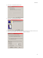

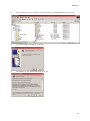
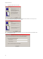


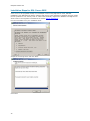

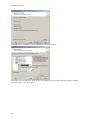


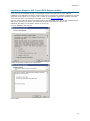
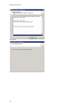
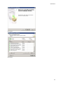
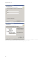
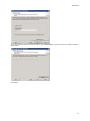
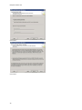
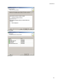
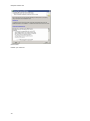

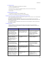

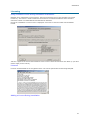


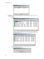
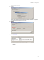
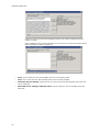

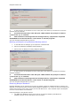
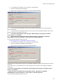
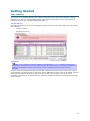


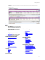
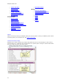


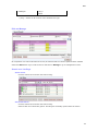
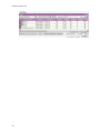

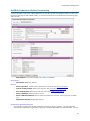
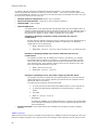

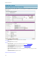
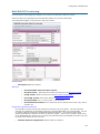
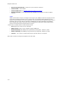

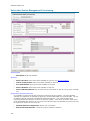
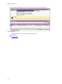

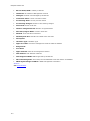


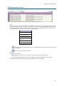
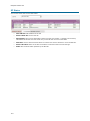

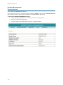

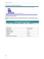


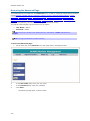


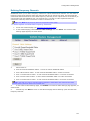


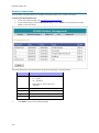
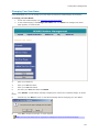

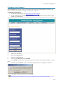

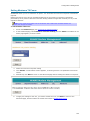
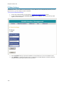
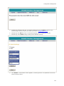
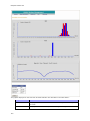
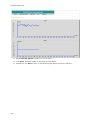

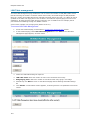


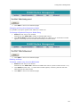
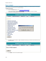

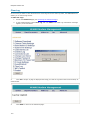
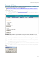
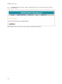

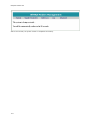

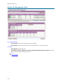


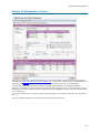
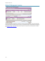


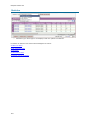


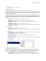

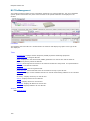


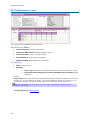


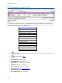

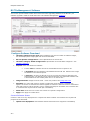


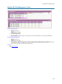


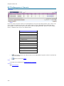
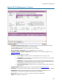


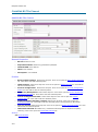

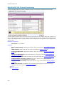

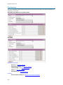

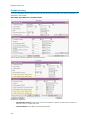


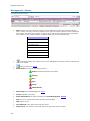


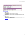

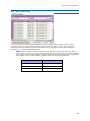
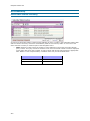
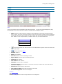


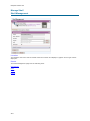
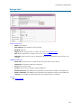
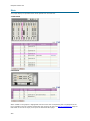


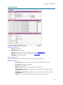

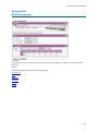

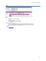
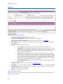

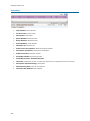
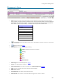

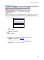
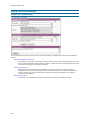
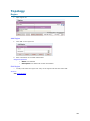


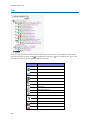
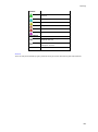

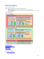
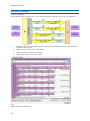


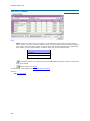


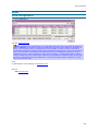


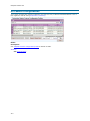
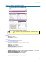

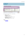

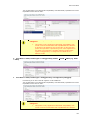


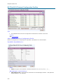


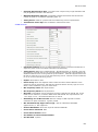
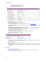


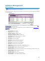


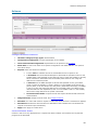

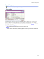


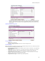


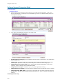
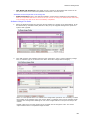
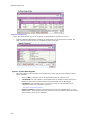
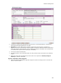


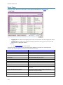

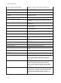

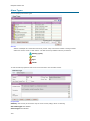
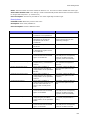

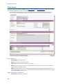


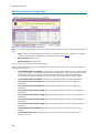
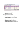


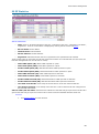
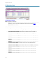


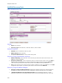
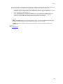
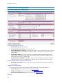
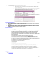


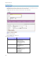


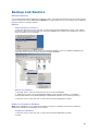
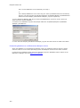


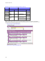
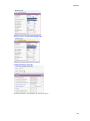

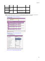


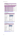

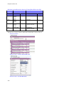
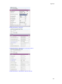

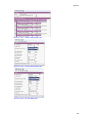
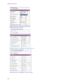
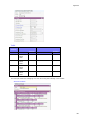

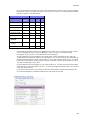

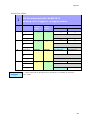

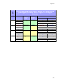


![Identifying Embeded Web Servers - [media.blackhat.com]](http://vs1.manualzilla.com/store/data/005833288_1-dd26f65aacb79f754f7b5aa134b8197a-150x150.png)