1
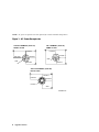
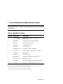
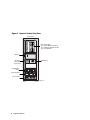
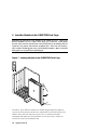
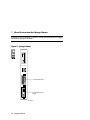
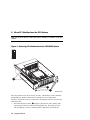
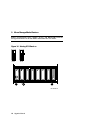
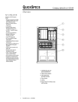
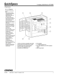
GS60/8200 to GS60E
Upgrade Manual
Order Number:
EK–GS60E–UP. A01
Use this manual as a quick reference to upgrade an AlphaServer
GS60 or AlphaServer 8200 to an AlphaServer GS60E system.
Compaq Computer Corporation
First Printing, August 1999
The information in this publication is subject to change without notice.
COMPAQ COMPUTER CORPORATION SHALL NOT BE LIABLE FOR TECHNICAL
OR EDITORIAL ERRORS OR OMISSIONS CONTAINED HEREIN, NOR FOR
INCIDENTAL OR CONSEQUENTIAL DAMAGES RESULTING FROM THE
FURNISHING, PERFORMANCE, OR USE OF THIS MATERIAL.
This publication contains information protected by copyright. No part of this publication may
be photocopied or reproduced in any form without prior written consent from Compaq
Computer Corporation.
The software described in this document is furnished under a license agreement or
nondisclosure agreement and may be used or copied only in accordance with the terms of the
agreement.
© 1999 Compaq Computer Corporation.
All rights reserved. Printed in the U.S.A.
COMPAQ and the Compaq logo are trademarks or registered trademarks of Compaq
Computer Corporation. AlphaServer, DIGITAL, OpenVMS, and StorageWorks are
trademarks or registered trademarks of Digital Equipment Corporation. Microsoft, Windows,
and Windows NT are registered trademarks of Microsoft Corporation. UNIX is a registered
trademark in the U.S. and other countries, licensed exclusively through X/Open Company Ltd.
Other product names mentioned herein may be trademarks and/or registered trademarks of
their respective companies.
FCC Notice: The equipment described in this manual generates, uses, and may emit radio
frequency energy. The equipment has been type tested and found to comply with the limits for
a Class A digital device pursuant to Part 15 of FCC Rules, which are designed to provide
reasonable protection against such radio frequency interference. Operation of this equipment
in a residential area may cause interference, in which case the user at his own expense will be
required to take whatever measures are required to correct the interference.
Shielded Cables: If shielded cables have been supplied or specified, they must be used on the
system in order to maintain international regulatory compliance.
Warning! This is a Class A product. In a domestic environment this product may cause radio
interference, in which case the user may be required to take adequate measures.
Achtung! Dieses ist ein Gerät der Funkstörgrenzwertklasse A. In Wohnbereichen können bei
Betrieb dieses Gerätes Rundfunkstörungen auftreten, in welchen Fällen der Benutzer für
entsprechende Gegenmaßnahmen verantwortlich ist.
Avertissement! Cet appareil est un appareil de Classe A. Dans un environnement résidentiel,
cet appareil peut provoquer des brouillages radioélectriques. Dans ce cas, il peut être demandé
à l'utilisateur de prendre les mesures appropriées.
Contents
Preface ................................................................................................................ v
Procedure
1 Overview............................................................................................................. 1
2 Prepare the Site.................................................................................................... 2
3 Check All Materials and Position the New Cabinet.............................................. 5
4 Power Down the GS60 or 8200 System................................................................ 8
5 Remove the Modules from the GS60/8200 TLSB Card Cage............................. 10
6 Insert the Modules in the GS60E TLSB Card Cage............................................ 12
7 Move Devices from the Storage Drawer ............................................................ 14
8 Move PCI Modules from the PCI Shelves.......................................................... 16
9 Move StorageWorks Devices............................................................................. 18
10 Power Up and Verify the System ....................................................................... 20
Examples
1 Show Config Command....................................................................................... 2
2 Verifying the System ......................................................................................... 20
Figures
1 AC Power Receptacles......................................................................................... 2
2 System Cabinet, Front View ................................................................................ 6
3 System Circuit Breakers ...................................................................................... 8
4 Removing Modules from the GS60/8200 TLSB Card Cage ............................... 10
5 Removing I/O Cables ........................................................................................ 11
6 Hose Numbering Scheme for KFTHA ............................................................... 11
7 Inserting Modules in the GS60E TLSB Card Cage............................................. 12
8 Storage Drawer.................................................................................................. 14
9 Removing PCI Modules from the GS60/8200 System ........................................ 16
10 Moving SCSI Devices....................................................................................... 18
11 Power Supply LEDs.......................................................................................... 21
iii
Tables
1
2
3
4
AlphaServer 8200/GS60/GS60E Documentation ................................................ vi
Three-Phase AC Input Voltages........................................................................... 3
Three-Phase Power Requirements........................................................................ 3
Upgrade Kit Contents .......................................................................................... 5
Index
iv
Preface
Intended Audience
This manual is written for the customer service engineer.
Document Structure
This manual uses a structured documentation design. Topics are organized into
small sections for efficient online and printed reference. Each topic begins with an
abstract. You can quickly gain a comprehensive overview by reading only the
abstracts. Next is an illustration or example, which also provides quick reference.
Last in the structure are descriptive text and syntax definitions.
Conventions Used in This Document
Icons. Icons similar to those shown below are used in illustrations for designating
part placement in the system described. A shaded area in the icon shows the location
of the component or part being discussed.
Main Cabinet
Front
Rear
Documentation Titles
Table 1 lists the relevant AlphaServer documentation.
v
Table 1 AlphaServer 8200/GS60/GS60E Documentation
Title
Order Number
Hardware User Information and Installation
GS60E Operations Manual
EK–GS60E–OP
GS60E Installation Guide
EK–GS60E–IN
Service Information Kit
8200/8400 Service Manual (hard copy)
EK–T8030–SV
GS60E Service Manual
EK–GS60E–SV
Reference Manuals
System Technical Manual
EK–T8030–TM
System Technical Manual Supplement: CPU
EK–T8030–TS
GS60E and GS140 Getting Started with Logical Partitions
EK–TUNLP–SF
DWLPA/DWLPB PCI Adapter Technical Manual
EK–DWLPA–TM
Upgrade Manuals
KN7CG CPU Module Installation Card
EK–KN7CG–IN
MS7CC Memory Installation Card
EK–MS7CC–IN
KFTHA System I/O Module Installation Card
EK–KFTHA–IN
KFE72 Installation Guide
EK–KFE72–IN
DWLPA/DWLPB PCI PIU Installation Guide
EK–DWL84–IN
H7506 Power Supply Installation Card
EK–H7506–IN
RRDCD Installation Card
EK–RRDXX–IN
vi
Procedure
1 Overview
Following are the steps to upgrade an AlphaServer GS60 or 8200 to an AlphaServer
GS60E:
1.
Prepare the site.
2.
Check all materials and position the new cabinet.
3.
Power down the GS60 or 8200 system.
4.
Remove the modules from the GS60/8200 TLSB card cage.
5.
Insert the modules in the GS60E TLSB card cage.
6.
Move devices from the storage drawer.
7.
Move PCI modules from the PCI shelves.
8.
Move StorageWorks devices.
9.
Power up and verify the system.
Procedure 1
2 Prepare the Site
Get a hard copy of the 8200/GS60 system configuration, note any additional
options you may be adding with this upgrade, and make certain three-phase AC
power is available.
Example 1 Show Config Command
P08>>> show config
Name
TLSB
4++
KN7CE-AB
5++
KN7CE-AB
6+
MS7CC
7+
MS7CC
8+
KFTIA
C0 Internal PCI connected to kftia0
0+
ISP1020
1+
ISP1020
2+
DECchip 21040-AA
3+
DEC PCI FDDI
4+
ISP1020
5+
ISP1020
6+
DECchip 21040-AA
7+
PCI NVRAM
C1 PCI connected to kftia0
0+
SIO
0+
1+
2+
3+
Controllers on SIO
DECchip 21040-AA
FLOPPY
KBD
MOUSE
EISA connected to pci1 through sio0
3+
KFESB
P08>>>
2 Upgrade Manual
Type
Rev
Mnemonic
8014
8014
5000
5000
2020
0000
0000
0000
0000
0000
10201077
10201077
21011
F1011
10201077
10201077
21011
71011
0001
0001
0023
0000
0001
0001
0023
0000
4828086
0003
pci0
isp00
isp01
tulip0
pfi0
isp02
isp03
tulip1
pci_nvram0
pci1
sio0
21011
2
3
4
0023
0000
0000
0000
sio0
tulip2
floppy0
kbd0
mouse0
2EA310
0000
kn7ce-ab0
kn7ce-ab1
ms7cc0
ms7cc1
kftia0
eisa0
Shut down the operating system and issue the console commands show configuration,
show device, and show <envar> to show the system configuration and environment
variables. Keep a hard copy of the output for reference.
CAUTION:
Since you are moving from a working system, keep the existing
configuration. Keep the same I/O cable connections to adapter
modules, adapter connections to devices, and keep StorageWorks device
numbering by keeping the same position of the device in a Storage–
Works shelf. If you keep these the same, there will be no need for
device reconfiguration.
Tables 1 and 2 list the three-phase voltage and power requirements. Figure 1 shows
the required AC power receptacles.
Table 2
Three-Phase AC Input Voltages
Country
Input
Voltage
Circuit Breaker
Rating (amps)
Frequency
Range (Hz)
Japan
202 Delta
30
50–60
North America
120/208 Wye
30
50–60
Europe/AP
380–415 Wye
32
50–60
Each system and expander cabinet requires its own AC power connector.
Table 3
Three-Phase Power Requirements
Cabinet
Power (watts)
Heat Dissipation (BTU/hr)
System
1,200 minimum¹
2,450 maximum²
4,100 minimum¹
8,300 maximum²
System and two
expander cabinets
5,150 maximum³
17,550 maximum³
¹These figures are based on a minimum configuration containing three power supplies, a dual
CPU module, one memory module, one system I/O module, one CD-ROM, one minimally
configured PCI shelf, and one StorageWorks shelf with one disk drive.
²Based on a fully configured system containing three power supplies, three CPU modules (6
CPUs), two memory modules, two system I/O modules, one CD-ROM, two PCI shelves, and two
StorageWorks shelves with 12 disk drives.
³Based on a fully configured system cabinet (see note 2) and two expander cabinets each
containing three PCI shelves and four StorageWorks shelves with 24 disk drives.
Procedure 3
NOTE: AC power receptacles are also required for console terminals and printers.
Figure 1 AC Power Receptacles
202 V NOMINAL (50-60 Hz)
NEMA L21-30R
120/208 V NOMINAL (50-60 Hz)
NEMA L21-30R
V
V
V
V
PHASE X
PHASE X
PHASE Y
PHASE Y
NEUTRAL
GND
GND
PHASE Z
PHASE Z
V
V
380-415 V NOMINAL (50-60 Hz)
IEC 309 TYPE
V
V
PHASE 3
PHASE 2
NEUTRAL
PHASE 1
GND
V
GS60E24-99
4 Upgrade Manual
3 Check All Materials and Position the New Cabinet
Unpack and position the new cabinet. Review what needs to be moved from the
old cabinet into the new cabinet. The Upgrade Kit also contains the GS60E
documentation.
Table 4 Upgrade Kit Contents
Quantity Part Number
Description
1
3X-H9A22-AA
-AB
GS60E System Cabinet, USA/Japan (-AA)
Europe (-AB)
1
BA36R-RE
StorageWorks shelf (wide UltraSCSI)
1
E2052-AA
KFTHA I/O port module
4
E2034-AA
Terminator modules
1
54-24776-01
Clock module
1
QB-4NQAA-SA
QUK INST UT MUL SRL/RX23
1
17-03567-08
Cable assembly, 68-pin 90-degre, 50 cond
1
36-26123-07
Return label
1
36-00551-02
Model 6/525 label
1
EK-GS60E-UP
GS60/8200 to GS60E Upgrade Manual
1
3X-KN7CG-AB
Dual-CPU module¹
1
75-00518-02
AlphaServer GS60E Tru64 UNIX software kit²
1
75-00518-01
AlphaServer GS60E OpenVMS software kit³
¹CPU module comes with the 8200 to GS60E upgrade kit, DA-, DY-76U8B-AA, -AB.
²OpenVMS software comes with DY-76U8A-AA, -AB kits.
³Tru64 UNIX software comes with DA-76U8A-AA, -AB kits.
Procedure 5
Figure 2 System Cabinet, Front View
(Front View)
7-Slot System Bus
Up to 3 CPU Modules (6 CPUs)
Up to 5 Memory Modules (12 GB)
Up to 3 I/O Modules
Blowers
CD Drive
(and optional
floppy drive)
DWLPB PCI
StorageWorks
Shelf
Power Supplies
AC Input Box
OM22-99
6 Upgrade Manual
Already installed in the new cabinet are the following:
•
TLSB card cage
•
CD-ROM drive
•
Operator control panel
•
CCL panel
•
One StorageWorks shelf
•
One PCI shelf
•
Three power supplies
The following items need to be removed from your existing cabinet and installed in
the new cabinet:
•
Disk or tape drives and the StorageWorks power supply from the storage drawer
•
I/O, memory, and terminator modules from the TLSB card cage; and CPU
module for the 8200 to GS60E upgrade
•
Second PCI shelf
•
Second StorageWorks shelf
Tools
Small and large flathead screwdrivers
Small and large Phillips head screwdrivers
Antistatic bags
One for each TLSB and PCI module
WARNING: At least two people are required to remove the cabinet from the pallet.
Serious injury may result if the cabinet is improperly handled or
proper safety conditions are not met.
Unpack the new cabinet and move it into position. Save the packing box for the
return of the old cabinet.
Procedure 7
4
Power Down the GS60 or 8200 System
Turn off power to the existing system.
Figure 3 System Circuit Breakers (shown with redundant power
supply)
Rear View
Rear
2
J1
J2
J3
3
2
AC Input
BX-0331-99
8 Upgrade Manual
1.
With the system in console mode, depress the pushbutton on the control panel to
the Off position (out).
2.
Open the rear door of the cabinet, and,
3.
•
If the system has two power regulators, push both breakers on the power
strip (in the middle of the cabinet) to the right.
•
If the system has one power regulator, push the handle down on the circuit
breaker (at the bottom of the cabinet) (see ➋ in Figure 3).
Unplug the power cord from the power strip or from the regulator (see ➌).
Procedure 9
5 Remove the Modules from the GS60/8200 TLSB
Card Cage
Put on an antistatic wrist strap, remove all TLSB modules, and place them in
antistatic bags. Inspect all removed modules for damage. Any connector
damage and any bent pins in the backplane must be repaired before a module is
inserted.
Figure 4 Removing Modules from the GS60/8200 TLSB
Card Cage
Front
2
BX-0768D-96
10 Upgrade Manual
Tools required: small and large flathead screwdrivers
1.
Ground yourself to the cabinet with the antistatic wrist strap.
2.
Remove each processor and memory module by pushing the handles of the
module in toward the module end plate and to the left, releasing them from the
stops. Grasp the end plate and slide the module out of the card cage. See ➋ in
Figure 4. Place each module in an antistatic bag as it is removed from the card
cage. Remove any filler modules.
3.
At the rear of the cabinet, use the small flathead screwdriver to disconnect all
I/O cables from KFTIA and KFTHA modules (see Figure 5). Label each hose
with the connector number from which it is being detached. Figure 6 shows the
connector (C0, C1, etc.) numbering scheme. The KFTHA has four hose
connectors, numbered in increasing order from top to bottom.
4.
Remove the KFTIA and KFTHA modules using the procedure in step 2.
Figure 5 Removing I/O Cables
3
3
BX-0756B-96
Figure 6 Hose Numbering Scheme for KFTHA
Centerplane
C0 C4 C8
C3 C7 C11
8 7 6 5 4 TLSB node
BX-0164A-96
Procedure 11
6 Insert the Modules in the GS60E TLSB Card Cage
Determine the placement of the modules in the TLSB card cage. Inspect the
KN7CG module’s top row of pins on the large gray connector. If the plastic
portion of the connector obstructs the connector pin hole(s), the damage must be
repaired or the plastic will bend the backplane pins. Insert the I/O, memory,
CPU (GS60 to GS60E upgrade only), and terminator modules. Make certain the
EMI gaskets are in position and not damaged.
Figure 7 Inserting Modules in the GS60E TLSB Card Cage
Front
2
BX-0768D-96
CAUTION: If you add CPU modules, the modules shipped might have different
versions of console firmware. Results are unpredictable if you install all processor
modules at the same time and power up the system, so install each module
individually and update the console firmware on each if necessary. Follow the
instructions on the CPU installation card.
12 Upgrade Manual
Tools required: small flathead screwdriver
1.
Before installing the modules, determine their placement:
a.
Processor modules start at slot 0 and work up to slot 2.
b.
The first KFTHA module goes in slot 8, a second in slot 7, and a third in
slot 6.
c.
The first MS7CC memory module is in the highest-numbered open slot, the
next in the lowest-numbered open slot, and so on, alternating between
highest- and lowest-numbered open slots.
d.
Fill all remaining open slots with terminator modules (E2034-AA).
2.
Ground yourself to the cabinet with the antistatic wrist strap.
3.
Insert the I/O, memory, and terminator modules (if any) in the TLSB card cage.
CAUTION: To avoid damaging an EMI gasket, insert modules from left to right.
These gaskets can easily break, and a broken piece of gasket can damage a
module or the centerplane.
a.
Remove each module from its antistatic bag and release the spring-loaded
handles from the stops. To do this, push both handles toward the module
endplate and away from the stops.
b.
Hold the module assembly by the endplate. Align the module with the card
guide and the cover with the rail (see Figure 7).
c.
Slide the module into the card cage as far as it will easily go.
d.
When the module stops, check that the projections on the top and bottom of
the endplate are aligned with the slots in the card cage. If they are not,
remove the module and realign it.
e.
Push both handles at the same time to the module endplate. You will feel
the module make contact with the connectors at the centerplane. Release the
handles so they spring back into the stops.
4.
Attach the I/O cables to the KFTHA modules.
5.
Insert the processor modules.
Procedure 13
7 Move Devices from the Storage Drawer
From the front move the disk or tape drive and the StorageWorks power supply,
and from the rear move the disks.
Figure 8 Storage Drawer
Front
StorageWorks Drive
StorageWorks Power
Supply
BX-0604D-97
14 Upgrade Manual
Remove the storage device from the front of the storage drawer and the power
supply. Remove any devices from the rear of the drawer. Install them in the new
cabinet.
NOTE: The storage drawer supports only narrow SCSI disks.
Procedure 15
8 Move PCI Modules from the PCI Shelves
Slide out one PCI shelf at a time and remove modules for transfer to the new
cabinet.
Figure 9 Removing PCI Modules from the GS60/8200 System
Front
4
1
2
BX-0450G-96
Move the contents of one PCI card cage at a time. This makes it easier to maintain
the KFTHA hose number connections, to eliminate device reconfiguration.
Likewise, transfer the I/O devices connected to the adapters from one PCI card cage
at the same time.
1.
Disconnect the power cables, ➊ in Figure 9, the I/O hose cable, and any other
cables that prevent the PCI shelf from being pulled out. Keep the hose cable
with the adapters you remove from the shelf, so that when you transfer the
16 Upgrade Manual
adapters the hose number connections remain the same. (Remember that you
labeled the hoses when removing them from the KFTHAs.)
2.
Remove the five Phillips head screws that hold the card cage and the cable
management rack to the frame (see ➋).
3.
Pull the shelf out fully.
4.
Remove the top cover by loosening the two quarter-turn screws, lifting the top of
the cover away from the card cage, and then pulling the cover to the right and
off (see ➍).
5.
Remove any cables attaching I/O devices to the PCI from the front of PCI option
cards. Label each adapter and each shelf or I/O device to which it is connected,
for reinstallation.
6.
Note the slot number from which the option is being moved. Lift each PCI
option from its slot carefully, and place it in an antistatic bag. Label the bag
with the slot number. Also label the bag to indicate the shelf or device to which
it was attached, and label the I/O device(s) to show which devices belong to
each option.
7.
When all PCI option cards have been removed from one shelf, reattach the top
cover and slide it back into the cabinet. Reattach the mounting screws.
8.
Move the PCI option cards and the I/O cables to the new cabinet.
NOTE: If you are transferring more than 12 PCI I/O options, you will need to order
another DWLPB–DA.
Install PCI Modules
1.
Remove the face plates from any slots you plan to use for PCI options. The face
plates are held in place by a Phillips head screw on the inside right front edge of
the card cage.
2.
Insert the option boards.
3.
Attach the hose I/O cable to the proper KFTHA connector and to the PCI card
cage whose contents you just transferred.
NOTE: KFE70-XX and EISA cards are not supported in the GS60E system.
Procedure 17
9 Move StorageWorks Devices
Remove StorageWorks power supplies, devices, and DWZZA/Bs from the
StorageWorks shelves in the old cabinet and install in the new cabinet.
Figure 10 Moving SCSI Devices
Front
Rear
1
3
2
BX-0638A-96
18 Upgrade Manual
To remove SCSI devices from StorageWorks shelves:
1.
Disconnect the input power cord from the power supply. See ➊ in Figure 10.
2.
Unplug the I/O cable from the shelf (see ➋).
3.
Mark the position of each disk in the shelf, so that all disks can be restored with
the same unit numbers in the new cabinet. Remove power supply, DWZZA/Bs,
and I/O devices by pressing in both mounting tabs (see ➌). Using both hands to
support the weight, slide each unit out of the shelf.
NOTE: If you are transferring more than seven disks, you will need to order another
BA36R-RC.
To install the SCSI I/O devices in the new cabinet:
1.
Make sure that the shelf the devices are being placed in can be connected to the
same numbered hose connector as in the existing system.
2.
Insert the devices in the same places in the new shelf that they occupied in the
old shelf. Press in on the mounting tabs and using the other hand to support the
unit, slide the unit into the shelf until it connects.
3.
Reconnect the I/O cable to the shelf and to the PCI adapter to which it was
originally connected.
4.
Connect the power supply cord.
5.
Move any other I/O devices or external controllers and cable them.
Procedure 19
10 Power Up and Verify the System
Turn on the system, run console diagnostics, and issue the test command. Check
the system configuration against the old configuration. Boot the operating
system and run VET.
Example 2 Verifying the System
P00>>> sho sys_model_num
sys_model_num
➏
GS60E
If it is not set to GS60E on power-up, the map will show this as follows: Use the
set sys model number command to set the model to GS60E, as shown below.
.
.
.
.
.
.
.
. . .
. A1 A0
. 4GB 4GB
.
.
.
.
.
.
.
.
.
.
.
.
.
.
.
.
.
.
C3
ILV
8GB
AlphaServer GS60 8-6/525/4, Console V5.5-17 12-AUG-1999
15:03:35
SROM V2.3, OpenVMS PALcode V1.61-5, Tru64 UNIX PALcode V1.54-3
System Serial = qv, OS = OpenVMS, 15:52:29 August 23, 1999
P00>>> sho sys_model_num
sys_model_num
GS60
(or AS8200)
P00>>> set sys_model_num GS60E
P00>>> test
[test for all system devices appears]
P00>>> boot
20 Upgrade Manual
1.
Plug in the AC power cord.
2.
Set the main AC circuit breaker to the on position.
3.
Push the control panel On/Off button to on.
4.
To verify power supply operation, check the VAUX and 48V LEDs on all power
supplies (see Figure 11). With AC power on and the keyswitch on, both LEDs
should be On.
5.
Check that all modules are listed in the self-test display. Also check that the
LEDs on all modules light.
6.
Check the system serial number (see ➏) and change if necessary. Run console
diagnostics with the test command.
7.
Boot the operating system and run the verification exerciser tool (VET).
8.
Pack the old cabinet in a shipping box and return to Compaq, using the shipping
label supplied.
NOTE: Refer to the AlphaServer GS60E Operations and Service Manuals
for more information.
Figure 11
Power Supply LEDs
VAUX LED (top)
Power
Supplies
Front
48V LED (bottom)
Procedure 21
Index
A
AC input box, 6
AC input voltages, 3
AC power receptacles, 4
B
BA36R-RC, 19
Blowers, 6
C
Cabinet, front view, 6
Cabling, 11
CD-ROM, 6
Checking materials, 5
Circuit breakers, 8
Configuration, 2
Configuration rules for card cage, 13
D
DWLPB, 6, 17
E
E2034-AA terminator modules, 5
Environment variables, 3
H
O
Overview, 1
OpenVMS, 5
P
PCI modules, 16
Power supply LEDs, 21
Power requirements, 3
Powering down the system, 8
Preparing the site, 2
R
Recording the system configuration, 3
Removing I/O cables, 11
Removing modules, 10
Return of 8200/GS60, 21
S
SCSI devices, 15
Set –show system model number
command, 20
Show configuration command, 2
Storage drawer, 14
System verification, 21
T
H9A22 options, 5
Heat dissipation, 3
Hose numbering, 11
Terminator modules, 5, 13
Test command, 21
Tools required, 7, 11, 13
Tru64 UNIX, 5
I
U
I/O cables, 11
Inserting modules, 12
Upgrade kit contents, 5
M
Verification, 20
V
Modules, 12
Moving StorageWorks devices, 18
Index-1