1
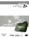
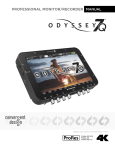
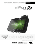
VR-100A: User Manual
1
Manovega VR-100A Manual
Support Info
Manovega Pte Ltd, #03-20, 71 Ayer Rajah Crescent, Singapore, 139951
Telephone: +65 96417415 (Singapore) +1 (408) 335-7611 (USA)
Email: [email protected]
Manovega VR-100A Manual
Contents
1 Introduction
4
Welcome . . . . . . . . . . . . . . . . . . . . . . . . . . . . . . . . . . . . . . . . . . . . . . . . .
4
How it works . . . . . . . . . . . . . . . . . . . . . . . . . . . . . . . . . . . . . . . . . . . . . . .
4
Network Topologies . . . . . . . . . . . . . . . . . . . . . . . . . . . . . . . . . . . . . . . . . . .
4
Server modes
. . . . . . . . . . . . . . . . . . . . . . . . . . . . . . . . . . . . . . . . . . .
4
Client Modes . . . . . . . . . . . . . . . . . . . . . . . . . . . . . . . . . . . . . . . . . . . .
5
What's in this Guide? . . . . . . . . . . . . . . . . . . . . . . . . . . . . . . . . . . . . . . . . . .
5
2 Quickstart: Start Streaming Now!
What's in the Box?
6
. . . . . . . . . . . . . . . . . . . . . . . . . . . . . . . . . . . . . . . . . . .
6
Live Video Streaming Using The Teradek Cube Encoder using RTSP push . . . . . . . . . . . . . .
6
3 The VR-100A Unit
7
The Back Panel . . . . . . . . . . . . . . . . . . . . . . . . . . . . . . . . . . . . . . . . . . . . .
7
The Front Panel . . . . . . . . . . . . . . . . . . . . . . . . . . . . . . . . . . . . . . . . . . . . .
7
4 Vega Client GUI
8
Accessing the GUI . . . . . . . . . . . . . . . . . . . . . . . . . . . . . . . . . . . . . . . . . . . .
8
Using the GUI: The Home Page
. . . . . . . . . . . . . . . . . . . . . . . . . . . . . . . . . . . .
9
. . . . . . . . . . . . . . . . . . . . . . . . . . . . . . . . . . . . . . . .
9
Using the GUI: Status . . . . . . . . . . . . . . . . . . . . . . . . . . . . . . . . . . . . . . . . . .
9
Statistics . . . . . . . . . . . . . . . . . . . . . . . . . . . . . . . . . . . . . . . . . . . . . .
9
Vega Engine Status
Modem Table
. . . . . . . . . . . . . . . . . . . . . . . . . . . . . . . . . . . . . . . . . . .
Using the GUI: Conguring your stream
10
. . . . . . . . . . . . . . . . . . . . . . . . . . . . . . . .
10
Transmission . . . . . . . . . . . . . . . . . . . . . . . . . . . . . . . . . . . . . . . . . . . .
10
Local Settings . . . . . . . . . . . . . . . . . . . . . . . . . . . . . . . . . . . . . . . . . . .
10
Server Settings . . . . . . . . . . . . . . . . . . . . . . . . . . . . . . . . . . . . . . . . . . .
10
Encoder General . . . . . . . . . . . . . . . . . . . . . . . . . . . . . . . . . . . . . . . . . .
11
Encoder Audio . . . . . . . . . . . . . . . . . . . . . . . . . . . . . . . . . . . . . . . . . . .
11
Encoder Video . . . . . . . . . . . . . . . . . . . . . . . . . . . . . . . . . . . . . . . . . . .
11
Using the GUI: System and Wi-Fi
. . . . . . . . . . . . . . . . . . . . . . . . . . . . . . . . . . .
11
System . . . . . . . . . . . . . . . . . . . . . . . . . . . . . . . . . . . . . . . . . . . . . . .
11
Wi-Fi . . . . . . . . . . . . . . . . . . . . . . . . . . . . . . . . . . . . . . . . . . . . . . . .
11
5 Using the Vega Server
12
Running in Direct mode . . . . . . . . . . . . . . . . . . . . . . . . . . . . . . . . . . . . . . . . .
12
Running in Relay mode
12
. . . . . . . . . . . . . . . . . . . . . . . . . . . . . . . . . . . . . . . . .
A Troubleshooting: Tips and Techniques
Diagnosing the VR-100A
12
. . . . . . . . . . . . . . . . . . . . . . . . . . . . . . . . . . . . . . . .
12
. . . . . . . . . . . . . . . . . . . . . . . . . . . . . . . . . . . . . . . . .
12
Network Problems . . . . . . . . . . . . . . . . . . . . . . . . . . . . . . . . . . . . . . . . .
12
Modem Problems
Manovega VR-100A Manual
1
Introduction
Welcome
Thank you for choosing the Manovega VR-100A Wireless Video Router.
Thanks to the patented Vega
Engine, the VR-100A will allow you to stream live video over multiple bonded wireless broadband connections,
with glass to glass latencies as low as 1.5 seconds.
How it works
Figure 1: Architecture of Vega Engine system
In recent years, the availability of wireless broadband through networks such as 3G has rapidly increased.
These oer end users mobile access to the internet at reasonable download speeds, but are unable to handle
upload heavy applications such as live video streaming, which typically require access to a xed line or shortrange Wi-Fi network. Through our patented Vega Engine, Manovega have developed a solution that nally
brings mobility to live video over IP.
The Vega Engine is composed of two complimentary pieces of software the Vega Client (embedded on the
VR-100A unit) and the Vega Server (installed on a server). The Vega Client receives data, such as live video,
and splits it across the available wireless broadband connections, such as 3G/4G, Wi-Fi and WiMax. The
split data is recombined at the Vega Server. In other words, the available bandwidth is aggregated, allowing
for higher upload speeds. The result is live video streaming in areas where it would otherwise be impossible
to do so.
Network Topologies
The Vega Engine software allows for a range of network congurations depending upon the users requirements.
Server modes
Direct Mode
When data is being sent over any network, each leg of the journey adds a delay to the journey
time. Achieving low latencies is therefore a matter of reducing the number of legs of the journey. Ideally,
therefore, we would like to send data from the VR-100A directly to a PC. This is possible over a local network,
but that would limit the mobility of the user. Retaining mobility therefore necessitates that the data is sent
over the internet, using wireless broadband networks such as 3G/4G, WiMax etc. This adds a bit of time,
but we can still send data directly to a PC and achieve great results. So long as public IP address is available,
the VR-100A can stream directly to any server or PC.
4
Chapter 1
Introduction
Manovega VR-100A Manual
Relay Mode
If the PC or server you wish to stream to does not have a public IP address, the Vega Engine
network can congured so that another server (which does have a public IP) is used to relay the data to the
end server. Although this adds a second hop to the journey, and therefore additional latency, it does allow
streaming to any computer connected to the internet.
Client Modes
RTSP Push
In RTSP push mode, the VR-100A will try to send to the server any data it receives from the
encoder. This adds approximately 2 seconds to the total latency stream because the software of the VR-100A
is actively passing the data on.
RTSP Pull mode
In RTSP pull mode, the VR-100A acts instead as a router for the server, which asks for
data directly from the cube. In pull mode, the unit will send some dummy data to the server to check on the
connection to the server.
What's in this Guide?
•
Chapter 1: Introduction
•
This chapter describes the Vega Engine and the contents of this user guide
Chapter 2: Quickstart: Start Streaming Now!
This chapter describes what items are included in the VR-100A package and how to start streaming
out of the box.
•
Chapter 3: The VR-100A unit
•
Chapter 4: Vega Client GUI
•
This chapter describes use of the Vega Client GUI.
Chapter 5: Vega Server
•
This chapter describes the features of VR-100A unit.
This chapter describes operation of the Vega Server software.
Appendix 1: Troubleshooting
Chapter 1
This appendix describes common issues and solutions.
Introduction
5
Manovega VR-100A Manual
2
Quickstart: Start Streaming Now!
What's in the Box?
The VR-100A comes packaged with the following items:
•
The VR-100A unit
•
Broadband E180 HSPA USB Rotate Stick Modems (8 no.s)
•
Internal battery
•
Ethernet cable
•
Battery charger
•
Direct DC Adaptor for use with external 220V AC power source
•
Customised Carrying Case Using the GUI: Status
Optional purchases:
•
Teradek CubeTM H.264 Encoder
Live Video Streaming Using The Teradek Cube Encoder using RTSP push
This quickstart assumes that the Vega Engine software has been installed on your server already, and that
you are using the Teradek Cube Encoder. For more detail software see Section 6.
1. Connect the Teradek Cube Encoder to camera using a BRC cable. Connect the Cube to its battery.
2. Connect Teradek Cube Encoder to the VR-100A using the ethernet cable.
Connect VR-100A to its
battery.
3. Insert modems into VR-100A USB slots.
4. Push the power switch on the VR-100A to turn the unit on.
5. Use a smartphone, iPad or laptop to connect to the VR-100A Wi-Fi access point. The default is SSID
is VEGA-AP.
6. Open the Vega Client GUI by connecting to 172.16.1.1 in a web browser.
7. Open the conguration page. Make sure that the Encoder type is set to Wired Cube, and the Server
Settings correspond to the location of your server. Click the update button.
8. Congratulations! You are now streaming live video to your server! The stream can be viewed using
media players such as VLC at the address, udp://@:10000.
6
Chapter 2
Quickstart: Start Streaming Now!
Manovega VR-100A Manual
3
The VR-100A Unit
The Back Panel
Figure 2: The back panel of the VR-100A
DC 12V
This is the input for the power supply.
LED
When the LED is on, data is succesfully being sent to the Vega Server
COM1
Used to connect a monitor for troubleshooting purposes.
USB
These USB ports can be used for 3G/WiMax modems, Wi-Fi adaptors etc.
DVI
Used to connect a monitor for troubleshooting purposes.
LAN
This an ethernet port that can be used to connect to network devices, or to a PC.
PWR SW
Push this button to turn the unit on. When switched on, holding this button down
for approximately 5 seconds turns o the unit.
ANT
This is the antenna port for the on board Wi-Fi chipset.
The Front Panel
Figure 3: The front panel of the VR-100A
USB
Chapter 3
These USB ports can be used for 3G/WiMax modems, Wi-Fi adaptors etc.
The VR-100A Unit
7
Manovega VR-100A Manual
4
Vega Client GUI
The VR-100A has a powerful browser based GUI installed that controls the Vega Client. This section describes
how to access the GUI and how to use it.
Accessing the GUI
Because the GUI is browser based, the VR-100A can be controlled using devices such as smartphones, iPads
etc. To access the GUI, you must rst connect to the VR-100A access point. This can be done via a Wi-Fi
or ethernet connection. The default SSID of the VR-100A is VEGA-AP.
Figure 4: Connecting to the VR-100A Access Point
Once connected, open a browser window and enter the router's default IP address, 172.16.1.1, into the address
eld. If succesful, you will be presented with the GUI home page.
Figure 5: The GUI Client Home Page
8
Chapter 4
Vega Client GUI
Manovega VR-100A Manual
Using the GUI: The Home Page
The GUI home page displays the most important and useful information regarding the status of the Vega
Engine Network.
Vega Engine Status
Connection Status
Gives the current status of the connection to the Vega Server
Streaming Status
Gives the current status of data streaming to the Vega Server
Recording Status
States whether the Vega Server is saving the data stream.
Total Number Of Links
The number of wireless connections currently in use.
Total Bandwidth
The total bandwidth used by the VR-100A
Receiver Bandwidth
The total bandwidth available to the VR-100A from the network point.
Receiver Loss Rate
The average packet loss rate for the last 60 seconds.
A packet loss rate
above 1% will prevent smooth streaming at low latencies.
Reset Client
Restarts the Vega Client.
Reset Server
Restarts the Vega Server.
Start Recording
Commands the Vega Server to start recording incoming data to le.
Stop Recording
Commands the Vega Server to stop recording incoming data to le.
Bandwidth Graph
Displays the current bandwidth being used by each modem over time. The
blue line displays the bitrate at which the encoder is sending data to the
VR-100A.
Modem Table
Displays the current status of each modem, including connection type, current bandwidth use and packet round trip time.
Adaptive Encoding
The VR-100A can ask the video encoder to send data to it a constant bitrate
(which can be dened on the conguration page) or it can use ask for data
at a bitrate that varies according to the bandwidth available. Using adaptive
encoding, the VR-100A is able to stream at the best possible quality for a
given set of wireless networks.
Calculate Optimum
With the calculate optimum algorithm the VR-100A can determine the available bandwidth by attempting to send as much data as possible to the server,
and then measuring the round trip times of the packets it sent. Calculate
optimum then returns the excess available bandwidth at a variety of latency
settings. 0kbps indicates that network conditions would not be able to support streaming at that latency.
Using the GUI: Status
The Status page provides a more in depth look at the workings of the VR-100A.
Statistics
Bandwidth Graph
Displays the current bandwidth being used by each modem over time. The
blue line displays the bitrate at which the encoder is sending data to the
VR-100A.
Total Number Of Modems
The number of modems connected to the VR-100A at the current time.
ISP modems
The number of 3G modems connected to the corresponding ISP.
Other Links
The number of Wi-Fi, WiMax, ethernet connections etc. connected to the
VR-100A.
Chapter 4
Vega Client GUI
9
Manovega VR-100A Manual
Modem Table
Modem Name
Displays the modem name. For 3G modems, this is in the format ISP-n where
n is a number indicating the order of connection i.e. the 4th modem to be
plugged into the VR-100A from M1 will be called M1-4.
modems follow the same notation.
4G and WiMax
Wi-Fi connections are given the name
Wi-Fi-n, where n indicates the order of connection. Ethernet connections are
assigned names in the format eth(n) where (n) indicates the ethernet port
number.
IP
This is the IP address of the modem. If this is a public IP address, the GUI
client can be accessed from any device connected to the internet by typing
the IP address into a web browser.
Bandwidth
The bandwidth currently being used by the modem at the current time (in
kbps).
Total Bytes
The total data sent by the modem since connection.
RTT
The round trip time of packets sent by the modem.
Using the GUI: Conguring your stream
The GUI conguration page is used to dene the key parameters for succesful operation of the VR-100A.
Transmission
Delay
Sets the latency at which the VR-100A will send data.
Retransmission
Sets whether or not the VR-100A will attempt to resend lost packets.
Retransmission Count
Sets the number of retransmissions the VR-100A will attempt.
Local Settings
Local Wired IP
Sets the IP address at which the VR-100A will be found on a local network
if connected by the ethernet port.
Local Wireless IP
Sets the IP address at which the VR-100A will be found on a local network
if connected by Wi-Fi.
Local Wireless SSID
Sets the service set identier of the VR-100A on a local network if connected
by Wi-Fi.
Server Settings
Destination IP
This is the IP address of the server you wish to stream to.
Destination Port
This is the listening port of the server you wish to stream to.
Server Output IP
This is the IP address at which the stream will be found on the local network
of the server.
Server Output Port
This is the port at which the stream will be found on the local network of
the server.
10
Chapter 4
Vega Client GUI
Manovega VR-100A Manual
Encoder General
Encoder Type
This should be set to the encoder currently connected to the VR-100A.
Remote types are used for pulling data (i.e. the VR-100A will send data on
request from the Vega Server) while regular types are used for pushing data
(i.e. the VR-100A will constantly send data to the Vega Server). In Simple
and Test modes the VR-100A will generate dummy data to stream to the
Vega Server. This can be used for troubleshooting and testing.
Input Stream Type
The VR-100A can currently only use streams encoded in the RTSP protocol.
Encoder IP
This should be set to the IP address of the encoder.
Encoder HTTP Port
This should be set to the HTTP port of the encoder.
Encoder RTSP Port
This should be set to the RTSP port of the encoder.
Encoder Audio
Encoder Audio
Sets the bitrate at which the encoder attempts to encode audio.
Encoder Video
The settings available under this section are dependent upon the encoder type selected. The settings described
below are for the Teradek Cube encoder.
Adaptive Encoding
Sets whether or not adaptive encoding is used.
Encoding Bitrate
Sets the bitrate at which the encoder attempts to encode video.
Resolution
Sets the resolution at which the encoder attempts to encode video.
Frame Rate
Sets the frame rate at which the encoder attempts to encode video.
GOP Size
Determines the group of pictures structure.
Prole
Sets the compression prole. High is optimal for most applications.
Cache Latency
Sets the size of the cache. Decreasing this can reduce latency, but at the
expense of video stability. 300ms is optimal for most applications.
Safe Mode
Safe mode prevents the real encoding bitrate from going too high when the
encoder tries to match the set bitrate. In most applications, this should be
left on unless plenty of spare bandwidth is available.
Using the GUI: System and Wi-Fi
System
This page allow users to restore the VR-100A to the factory default and upgrading rmware.
Wi-Fi
1. Click the scan button to start scanning for WiFi networks.
2. Select a network to connect to.
Chapter 4
Vega Client GUI
11
Manovega VR-100A Manual
5
Using the Vega Server
To the start streaming to your server you must rst run the Vega Server software. The rst step is to connect
and locate the Vega Server les. All les relating to the Vega Server will be located in a folder named after
the software version number, e.g. folder name 1.0.6 for software version 1.0.6.
Running in Direct mode
To use the VR-100A in direct point-to-point mode, the program VegaServer.exe must be running on the end
device. VegaServer.exe takes the incoming split data and reassembles it in the correct fashion for playout.
An associated le, VegaServer.xml sets the listening port for the incoming stream, as well as the local IP
address at which the stream can be found. The stream can be played out by directing a media player such as
VLC to this IP address.
Running in Relay mode
To use the VR-100A in relay mode, VegaServer.exe must be running on the end device, but a UDP tunnel
must be set up between the relay server and the end device.
The tunnel can be started by running the
program simple_udp_server.exe on the relay server, and simple_udp_client.exe on the end device. As
before, listening ports for VegaServer.exe are dened in VegaServer.xml.
A
Troubleshooting: Tips and Techniques
Diagnosing the VR-100A
While using the VR-100A problems may arise that do not have an obvious source. In these cases you can use
SSH to investigate and determine the cause of the problem.
1. Connect the VR-100A to your computer using an ethernet cable.
2. Open a terminal and set your local IP address to 192.168.2.10/24. On Linux machines this can be done
using the command
sudo ifcong eth0 192.168.2.10/24.
3. Connect using SSH by typing
ssh [email protected].
When prompted, enter secret as the password.
4. You should now be connected to the root folder of the VR-100A's hard drive.
Modem Problems
There are a few problems that can cause modems to stop functioning properly. The rst thing to check is
that the USB ports are recognised. This can be done by entering the command
lsusb,
which will display all
connected USB devices. If the number of USB devices displayed is less than the number of USB modems
connected, it could be that the USB port is not functioning.
If the modem appears in the list as a USB storage device, then it is likely a driver issue. The VR-100A has a
Linux based operating system and can only use USB modems that have drivers available for Linux.
Network Problems
You can also use the command line to diagnose networking issues, e.g. cannot connect to the Wi-Fi access
point.
The command
ifcong
will display all the operating network devices.
If the Wi-Fi device does not
appear on this list, there is a hardware issue.
12
Chapter A
Troubleshooting: Tips and Techniques


![[P/N: MCB3101] Class I Serial Bluetooth Wireless](http://vs1.manualzilla.com/store/data/005819698_1-328d04723caa8571829b907b8cc9e0c6-150x150.png)