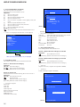
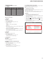
1
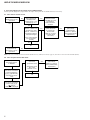
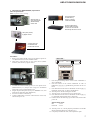
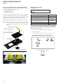
HBD-E780W/E980W/E985W SECTION 1 NOTAS DE SERVIÇO NOTES ON HANDLING THE OPTICAL PICK-UP BLOCK OR BASE UNIT The laser diode in the optical pick-up block may suffer electrostatic break-down because of the potential difference generated by the charged electrostatic load, etc. on clothing and the human body. During repair, pay attention to electrostatic break-down and also use the procedure in the printed matter which is included in the repair parts. The f exible board is easily damaged and should be handled with care. NOTES ON LASER DIODE EMISSION CHECK The laser beam on this model is concentrated so as to be focused on the disc ref ective surface by the objective lens in the optical pickup block. Therefore, when checking the laser diode emission, observe from more than 30 cm away from the objective lens. UNLEADED SOLDER Boards requiring use of unleaded solder are printed with the leadfree mark (LF) indicating the solder contains no lead. (Caution: Some printed circuit boards may not come printed with the lead free mark due to their particular size) : LEAD FREE MARK Unleaded solder has the following characteristics. • Unleaded solder melts at a temperature about 40 °C higher than ordinary solder. Ordinary soldering irons can be used but the iron tip has to be applied to the solder joint for a slightly longer time. Soldering irons using a temperature regulator should be set to about 350 °C. Caution: The printed pattern (copper foil) may peel away if the heated tip is applied for too long, so be careful! • Strong viscosity Unleaded solder is more viscous (sticky, less prone to f ow) than ordinary solder so use caution not to let solder bridges occur such as on IC pins, etc. • Usable with ordinary solder It is best to use only unleaded solder but unleaded solder may also be added to ordinary solder. RELEASING THE DISC TRAY LOCK The disc tray lock function for the antitheft of an demonstration disc in the store is equipped. Releasing Procedure: 1. Press the [?/1] button to turn on the system. 2. Touch the [FUNCTION] sensor to select “BD/DVD”. 3. Touch the [x] and [Z] sensors simultaneously and hold down unit “DEMO OFF” displayed on the fluorescent indicator tube (around 5 seconds). Note: When “DEMO LOCK” is displayed, the disc tray lock is not released by turning power on/off with the [?/1] button. ABOUT THE LENS CLEANING Do not do the lens cleaning with the cotton bud etc. It causes the trouble. 4 NOTE OF REPLACING THE IC101, IC304, IC307, IC501, IC702, IC5301 AND IC5307 ON THE MB-141 BOARD IC101, IC304, IC307, IC501, IC702, IC5301 and IC5307 on the MB-141 board cannot exchange with single. When these parts are damaged, exchange the complete mounted board. NOTE OF REPLACING THE IC106, IC107, IC206 AND IC207 ON THE MB-141 BOARD Replacement of IC106, IC107, IC206 and IC207 on the MB-141 board used in this unit requires a special tool. TEST DISC Part No. Description Layer J-6090-199-A BLX-104 Single Layer J-6090-200-A BLX-204 Dual Layer J-2501-307-A CD (HLX-A1) J-2501-305-A HLX-513 Single Layer (NTSC) J-2501-306-A HLX-514 Dual Layer (NTSC) J-6090-077-A HLX-506 Single Layer (PAL) J-6090-078-A HLX-507 Dual Layer (PAL) Note: Refer to the service manual of BDP-BX1/S350 (Part No. 9-883989-1[]) (page 1-3 to 1-14E) for the use of BLX-104/204. Operation and Display: 1. BLX-104 Procedure: 1. Select 23.976Hz/1080p. 2. Play “4.Motion picture”. 3. Check whether player can play back or not. 4. Check each outputs. Video: Composite/S Video/component/HDMI. Audio: Speaker out. * When 1080/24p monitor is nothing, 1080i (59.94Hz or 50Hz) can use instead of 1080/24p. However this is temporary correspondence. 2. BLX-204 Procedure: 1. Select 1080i (59.94Hz or 50Hz). 2. Play “4.Motion picture”. 3. Check whether player can play back or not (Check the picture and sound output). 3. CD (HLX-A1) Procedure: Check whether player can play back or not (Check the sound output). 4. HLX-513/514 (NTSC), HLX-506/507 (PAL) Procedure: 1. After displayed Main Menu, select “1.Video Signal”. 2. Play “1.Color bar 100%” (Check the picture and sound output). 3. Return to Menu. 4. Play “Demonstration 4:3” or “Demonstration 16:9” (Check the picture and sound output). HBD-E780W/E980W/E985W NOTE OF REPLACING THE OPTICAL DEVICE (KEM470AAA) OR MB-141 BOARD The password will be supplied to only service HQ, and service center name, q’ty and all of software registered information should be maintained by service HQ, and Audio will ask to report the registration information. Optical device (KEM-470AAA) for BD requires precise read out functions and secure contents protection system for more than past DVD/CD. Therefore, in the case repaired as follows, the writing work of the OP data is necessary. • • • When the optical device (KEM-470AAA) is replaced (The MB-141 board doesn’t replace). When both the optical device (KEM-470AAA) and MB-141 board are replaced. When the MB-141 board is replaced (The optical device (KEM-470AAA) doesn’t replace) (In this case, do the work of “3. Optical device (KEM-470AAA) replacement” other than the replacement of new optical device). Note: The servo adjustment is done while writing the OP data. The manual adjustment is unnecessary. LD ON TIME history doesn’t carry over. Do not touch any optical block parts, turn table and during replacing. BD laser diode is very sensitive. 1. Preparation 1-1. ESD Countermeasure It is necessary to conf rm the state of static electricity in the work space before the repair is started. The static electricity resistance of the BD laser is weaker than that of the DVD/CD laser. Do work space and worker’s ESD countermeasures to prevent destruction by ESD. 1-2. Jig • Digital camera (Recommend with macro mode) • USB memory • PC • Barcode decoder (Refer to “1-3. Barcode decoder (BDPRdec)”) 1-3. Barcode decoder (BDPRdec) Part No. : J-6090-212-A Jig name : BDPRdec.exe Release : 2010.11.26 Version : 2.0.0.0 Software contents : • BDPRdec.exe : Barcode decoder software • SavePath.ini : Decoded f le destination setting f le (Initial destination is “C:\BuData.txt”) • TasmanBars.dll : Decode dll • Uninst.exe : Uninstall the “BDPRdec.exe” from PC Install procedure: 1. Unzip the barcode decoder f les to any PC folder. 2. Check the attached 2D code photo (OK_sample.JPG) drag & drop onto “BDBUDec.exe”. When the barcode decoder is used for the f rst time, the password is necessary. It is unnecessary since the second times. Note 1: The password will be supplied to only service headquarters, and service center name/q’ty/all of software registered information should be maintained by service headquarters. Note 2: Do not change the decoded f le name “BuData.txt”. 3. When “.NET frame work requirements” is displayed, download following applications from Microsoft download site. • Microsoft .NET Framework Version 2.0 Redistributable Package (x86) http://www.microsoft.com/downloads/details.aspx?displaylan g=en&FamilyID=0856eacb-4362-4b0d-8edd-aab15c5e04f5 • Microsoft .NET Framework 2.0 Service Pack 1 (x86) http://www.microsoft.com/downloads/details.aspx?displaylan g=en&FamilyID=79bc3b77-e02c-4ad3-aacf-a7633f706ba5 How to use: Case 1 Drag & drop 2D code photo onto “BDPRdec.exe”. Case 2 Drag & drop BU data f le onto “BDPRdec.exe”. Data f le name be changed to specify format and end of 7 character are def ned. You can also enter the f le path at the prompt. 5 HBD-E780W/E980W/E985W 2. Pass-fail judgment of the optical device (KEM-470AAA) Perform pass-fail judgment to judge whether the repair of the optical device (KEM-470AAA) is necessary. 2-1. Flow of drive section check Confirm whether BD (BLX-104) can be reproduced NO YES Confirm whether the drive voltage is the following values CN5301 pin 3 : 12 V CN309 pin 1 : 5 V NO YES Confirm OP FFC cable (Part No. 1-838-615-11) and SPD FFC cable (Part No. 1-838-617-11), and replace it when it has been damaged NO Confirm F5301 to F5303 and F5305 on the MB-141 board, and replace it when it has been damaged Confirm whether the optical device IOP is normal in the service mode (Refer to “2-2. Flow of optical device IOP check”) NO Repalece the optical device (KEM-470AAA) (Refer to “3. Optical device (KEM-470AAA) replacement”) Then, confirm whether this unit operates normally YES OK Confirm whether DVD (HLX-513)/ CD (HLX-A1) can be reproduced NO Note: Refer to “2-14. OPTICAL PICK-UP BLOCK (KEM-470AAA), WIRE (FLAT TYPE)” (page 19) about how to remove the FFC HOLDER (REAR). 2-2. Flow of optical device IOP check Turn the power on, and change function to “BD/DVD” Press the buttons on the remote commander in order of [DISPLAY], [0], [2], [1] [SUBTITLE], and enter the service mode Press the buttons on the remote commander in order of [8], [7], [3], [ ], and the dIOP value is displayed 6 Confirm whether value is the specification value Specification value: BD: ±3 mA DVD/CD: ±3 mA YES OK NO Repalece the optical device (Refer to “3. Optical device (KEM-470AA) replacement”) HBD-E780W/E980W/E985W 3. Optical device (KEM-460AAA) replacement Flow of replacement: Note: The photo in f ow is an image. Save the text data to USB memory (memory capacity need not be 8GB) Barcode label on new optical device (KEM-470AAA) bottom side Connect USB memory with rear USB connector on this unit, and read the text data by the service mode Take photo (JPEG) by digital camera Change photo into the text data with the barcode decoder Procedure: 1. Remove the INSULATOR (4 pieces) and broken optical device (KEM-470AAA) from LOADING ASSY. 2. Take photo of the barcode on new optical device (KEM470AAA) bottom side by digital camera. – Rear view – LAN (100) Rear USB connector 3. Assemble the INSULATOR (4 pieces) to new optical device (KEM-470AAA), f x (Torque value: 2 kgf) it to LOADING ASSY with screw, and assemble this unit. 4. Drag & drop the taken photo by step 2 to “BDPRDec.exe”, and make the text data (File name: BuData.txt). 5. Save the text data to USB memory. 6. Connect USB memory with rear USB connector on this unit, and turn the power on. 7. Press the [FUNCTION] button on the remote commander to select “BD/DVD”. 8. Press the buttons on the remote commander in order of [DISPLAY], [0], [2], [1], [SUBTITLE], and enter the service mode. 9. Press the buttons on the remote commander in order of [8], [1], [ENTER], and execute “[1] Drive OP data Write”. 10. Turn the power off after writing the OP data. 11. Turn the power on, and enter the service mode again. 12. Press the buttons on the remote commander in order of [8], [7], [3], [ENTER], and the dIOP value is displayed. 13. Conf rm value is the following specif cation value, and turn the power off. Specif cation value: BD : ±3 mA DVD/CD : ±3 mA 14. Turn the power on, conf rm playback performance of the BD (BLX-104)/DVD (HLX-513)/CD (HLX-A1). 15. Completely assemble this unit, and complete the repair. 7 HBD-E780W/E980W/E985W Ver. 1.2 NOTE THE BD DRIVE (BPX-6) PARTS REPLACING The mechanism blocks except optical device of BD drive (BPX-6) are chief y composed of the following parts. • CHUCK HOLDER ASSY • LOADING ASSY • HOLDER, FFC (REAR) MODEL IDENTIFICATION - Rear view Part No. These parts are produced by two venders, it is not compatible. Therefore, CHUCK HOLDER ASSY and LOADING ASSY are supplied by one pair as repair parts. Please exchange both CHUCK HOLDER ASSY and LOADING ASSY at the same time. Model Part No. E780W: AEP, Italian and UK models 4-256-820-3[] E980W: Australian/ E985W: Singapore, Taiwan and Thai models 4-256-820-7[] HOLDER FFC (REAR) need not be exchanged at the same time. E980W: AEP, Italian/ E985W: Saudi Arabia models 4-256-820-8[] Note 1: The laser caution label is not pasted to LOADING FOR SERVICE. Please peel off an original laser caution label, and paste it to LOADING FOR SERVICE when you use LOADING FOR SERVICE. E780W: US model 4-257-163-1[] E980W: Canadian model 4-257-163-3[] LASER CAUTION LABEL LOADING FOR SERVICE CAPACITOR ELECTRICAL DISCHARGE PROCESSING When checking the board, the electrical discharge is necessary for the electric shock prevention. Connect the resistor to both ends of respective capacitors. • CHUCK HOLDER ASSY Switching regulator C1, C3, C4, C101, C102, C305, C306, C309, C310, C313 – SWICTHING REGULATOR (Conductor Side) – C102 LOADING ASSY C310 C101 C3 C4 C313 C1 HOLDER, FFC (REAR) (To both ends of each capacitor) /LPLWVDPSOHLQVWDWHRIODVHUFDXWLRQODEHO Note 2: If laser caution label is a condition of the figure below, it is acceptable. 800 :/2 W 8 C306 C305 C309 HBD-E780W/E980W/E985W Ver. 1.2 NOTE OF REPLACING THE IC3100 AND IC3200 ON THE AMP BOARD AND THE COMPLETE AMP BOARD When IC3100 and IC3200 on the AMP board and the complete AMP board are replaced, it is necessary to spread the compound (THERMAL COMPOUND (G747)) (Part No. J-2501-221-A ) between parts and heat sink. Spread the compound referring to the f gure below. – AMP Board (Component Side) – CHECKING METHOD OF NETWORK OPERATION It is necessary to check the network operation, when replacing the MB-141 board. Check the operation of wireless and wired LAN, according to the following method. 1. Checking Method of Wireless LAN Operation (HBD-E780W/E980W only) Check that access point is recognized surely. Necessary Equipment: Wireless access point with router function (AP) IC3100 IC3200 Procedure: 1. Press the [HOME] button on the remote commander to enter the home menu. 2. Press the [m]/[M]/[<]/[,] buttons on the remote commander to select “Network Settings”→“Internet Settings”, and press the [ ] button on the remote commander. 3. Press the [m]/[M] buttons on the remote commander to select “Wireless Setup (built-in)”, and press the [ ] button on the remote commander. 4. Press the [m]/[M] buttons on the remote commander to select “Scan”, and press the [ ] button on the remote commander. 5. The system starts searching for access points, and displays a list of up available network name (SSID). 6. Check that access point (SSID) is displayed on the searching result. Note: Refer to the instruction manual about details of the setting method. 2. Checking method of wired LAN operation Check that access point is recognized surely. IC3100 IC3200 Procedure: 1. Connect the main unit to the router or the hub, etc. with the LAN cable. 2. Press the [HOME] button on the remote commander to enter the home menu. 3. Press the [m]/[M]/[<]/[,] buttons on the remote commander to select “Network Settings”→“Internet Settings”, and press the [ ] button on the remote commander. 4. Press the [m]/[M] buttons on the remote commander to select “Wired Setup”, and press the [ ] button on the remote commander. 5. Press the [m]/[M]/[<]/[,] buttons on the remote commander to select “Auto”, and press the [ ] button on the remote commander. 6. Press the [,] button on the remote commander. 7. Press the [m]/[M] buttons on the remote commander to select “Save & Connect”, and press the [ ] button on the remote commander. 8. When “Internet Settings is now complete.” appears, then press the [ ] button on the remote commander. 9. Press the [HOME] button on the remote commander to enter the home menu. 10. Press the [m]/[M]/[<]/[,] buttons on the remote commander to select “Network Settings”→“Internet Settings”, and press the [ ] button on the remote commander. 11. Press the [m]/[M] buttons on the remote commander to select “Network Connection Diagnostics”, and press the [ ] button on the remote commander. 12. Press the [<]/[,] buttons on the remote commander to select “Start”, and press the [ ] button on the remote commander. 13. Check that IP address can be acquired. Note: Refer to the instruction manual about details of the setting method. 9 HBD-E780W/E980W/E985W SECTION 3 MODO DE TESTE COLD RESET The cold reset clears data except BD/DVD data stored in the RAM to initial conditions. Execute this mode when returning the unit to the customers. Procedure: 1. Press the [?/1] button to turn the power on. 2. Touch the [x] and [VOL –] sensors simultaneously and hold down (around 5 seconds). 3. The message “RESET” appears on f uorescent indicator tube, then becomes standby states. DEMO MODE This mode let you lock the disc tray. When this mode is activated, the disc will not eject when the [Z] sensor is touched. The message “DEMO LOCK” will be displayed on the fluorescent indicator tube. Procedure: 1. Press the [?/1] button to turn the power on. 2. Touch the [FUNCTION] sensor to select the “BD/DVD”. 3. Touch the [x] and [Z] sensors simultaneously and hold down until “DEMO LOCK” or “DEMO OFF” displayed on the fluorescent indicator tube (around 5 seconds). FACTORY INITIALIZE Return all of the unit setting to their factory defaults. Note 1: Disconnect the following connections when you use this mode. • Front USB • Rear USB • LAN • HDMI IN 1 • HDMI IN 2 Note 2: The operation in this mode must use a remote commander and TV monitor. Procedure: 1. Press the [?/1] button to turn the power on. 2. Press the [HOME] button on the remote commander, and the home menu is displayed. 3. Select “Setup” → “Resetting”, and press the [ ] button on the remote commander. Easy Setup Releasing method: Touch the [x] and [Z] sensors simultaneously and hold down until “DEMO OFF” displayed on the f uorescent indicator tube (around 5 seconds). PANEL TEST Procedure: 1. Press the [?/1] button to turn the power on. 2. Press button in order of the [DISPLAY] → [0] → [0] → [1] → [SUBTITLE] on the remote commander (Make the interval when each button is pressed within two seconds). 3. All segments in f uorescent indicator tube are lighted up. And half segments in f uorescent indicator tube are lighted up, others half segments in f uorescent indicator tube are lighted up, then all segments in f uorescent indicator tube are lighted up. This operation is repeated. 4. When all segments in f uorescent indicator tube are lighted up in the state of step 3, press the [VOL +] button on the remote commander and model information is displayed on the f uorescent indicator tube. Each time the [VOL +] button on the remote commander is pressed, the display changes from destination information, STR version in this order, and returns to the model information display. Each time the [VOL –] button on the remote commander is pressed, the version and date are switched. 5. In the state of step 3, press the [FUNCTION] button on the remote commander and “K 0” is displayed on the fluorescent indicator tube. “K 0” value increases whenever a button or sensor on the unit is pressed. However, once a button or sensor has been pressed, it is no longed taken into account. All button and sensors on the unit are pressed, “OK” and “K 7” are alternately displayed on the fluorescent indicator tube. Releasing method: To release from this mode, press the [?/1] button. Resetting 4. Select “Initialize Personal Information”, and press the [ button on the remote commander. ] Reset to Factory Default Settings Initialize Personal Information Erase personal data when disposing 5. Select “OK”, and press the [ mander. ] button on the remote com- Initialize Personal Information The information below will be deleted. Do you want to proceed? Playback history Internet video utilization information Internet content registered as Favorites OK Cancel 21 HBD-E780W/E980W/E985W 6. The message “Close” appears, and press the [ remote commander. ] button on the BD SERVICE MODE [Wireless checking fail on M07.R.179] Due to software bug in M07.R.179, currently Service mode do not support wireless checking features this version of software. For service to conf rm the wireless checking, please update customer sets to latest version of software. By using network upgrade method or Disc upgrade method. After f nish upgraded, Service member can perform wireless checking as mention in wireless LAN checking pages. Initialize Personal Information Initialization complete. Or Conf rm wireless LAN connection from customer mode, in case of Wireless connection successfully establish. The wireless Lan network connection will be judge as OK. Close Date: 26 January 2011 Note: The operation in this mode must use a remote commander and TV monitor. 7. Select “Reset to Factory Default Settings”, and press the [ button on the remote commander. ] Reset to Factory Default Settings Restore each setting to the factory d Initialize Personal Information 8. Select “All Settings”, and press the [ commander. ] button on the remote Reset to Factory Default Settings BD/DVD Viewing Settings Personal Control Settings Music Settings System Settings Network Settings All Settings 9. Select “Start”, and press the [ mander. ] button on the remote com- All Settings Restore all settings to the factory default settings. The system will turn off after reset. Start Cancel 10. Initialization ends when the message “WELCOME” on the f uorescent indicator tube disappears. 22 Setting method of the BD service mode: 1. Connect this unit with TV monitor. 2. Press the [?/1] button to turn the power on. 3. Press button in order of the [DISPLAY] → [0] → [2] → [1] → [SUBTITLE] on the remote commander. (Make the interval when each button is pressed within two seconds) 4. Enter the BD service mode. The OSD menu on TV monitor can be operated by remote commander. 1. Main Functions • Diag Performs unit test of devices installed on the board. • Display Error Log Error log is displayed. Displayed contents can also be saved in an USB memory device. • Factory Initialize Restores the unit to its factory settings. • Network Checks the wired network connection. • Version Up Not used. • System Information Displays the system information of the unit. Displays information such as the software version, drive information, etc. • EMC Test Mode Not used. • Drive Write drive OP data and check drive. HBD-E780W/E980W/E985W 2. Menu Tree Service Service Mode Mode Menu Menu [1] [1] Diag Diag [2] [2] Log Log [3] [3] Factory FactoryInitialize Initialize [4] [4] Network Network [5] [5] Version VersionUp Up [6] [6] System System Information Information [7] EMC Test Mode [8] Drive [9] HDD Mode Diag Diag Test Device Test US%D$CIFcon test Video Test Video output test $udio Test $udio output test $udio Input Test $udio Input Test :ireless L$N Test Not used Mic Test Not used HDMI Input Test HDMI Input Test Transcoder Test Not used Log Displays Error Log Error Log Displays error log Factory Initialize Initialize default setting Start Initialize Initialize default setting for the unit Network Network diagnosis for wired Ifconfig View network status Ping Confirm network connection Version Up Not used Start Update for %DP Not used System Information Displays system information Start Update for %DV Not used EMC Test Mode Not used Drive Write drive OP data and check drive HDD Mode Not used 23 HBD-E780W/E980W/E985W 3. Service Mode Menu (Top Menu) This is the top menu of service mode. Each function is accessed from this screen. Operation: [1] Moves to Diag screen [2] Moves to Log screen [3] Moves to Factory Initialize screen [4] Moves to Network screen [5] Moves to Version Up (DISC version update) screen (Not used) [6] Moves to System Information screen [7] Moves to EMC test mode screen (Not used) [8] Moves to Drive screen [9] Moves to HDD mode (Not used) [M]/[m] Moves the cursor [ ] Moves to the screen of the item selected with the cursor * Cursor is not displayed when the menu is f rst displayed. Service Mode Menu [1] [1]Diag Diag [2] Log [3] Factory Initialize [4] Network [5] Version Up [6] System Information [7] EMC Test Mode [8] Drive [9] HDD mode Diag Category: Device Test Diag Category: Device Test Device: USB Host Rear USB Media check ... OK Front USB Media check ... OK Checking... (Screen 1) (Screen 2) HELP: [RIGHT] [UP] [ENT] [RET] • Device Test: List of devices USB Host : USB media check (front and rear). Only one time. D/A Converter : DAC write check (non-verif cation). Ifcon : Not used in this unit. MIC : Not used in this unit. MFI : MFI read/write Check IPC : Device ID check External HDMI : Revision check Transcorder : Not used 5. Diag (Video/Audio Test) This screen performs video and audio tests. HELP : [DOWN] [ENT] [(NUM)] HELP (currently available keys, etc.) is displayed 4. Diag (Device Test) This screen is used to test devices mounted on the board. Screen 1: Selects the test category Operation: [<]/[,] Selects the category [m]/[ ] Moves to the selected category [RETURN] Returns to the service top menu Screen 1: When video test category is selected Operation: [ ] Shows/hides the color bar [M]/[RETURN] Returns to the selection of test category Screen 2: When audio test category is selected Operation: [ ] Plays back/stops the tone sound [M]/[RETURN] Returns to the selection of test category • Video test: Outputs a color bar (composite & component & HDMI). • Audio test: TONE sound output (speaker & HDMI). Screen 2: Device test Selects the device to test after selecting Device Test in screen 1. Operation: [<]/[,] Selects the device to test [ ] Executes the test [M] Returns to selection of test category [RETURN] Returns to selection of test category • List of test categories Device Test Video Test Audio Test Audio Input Test Wireless LAN Test (not used) Mic Test (not used) HDMI Input Test Transcoder Test (not used) Diag Category: Video Test [ENT] Show Color Bar Diag Category: Audio Test (Screen 1) HELP: [UP][ENT][RET] [ENT] Generate TONE Sound (Screen 2) 24 HELP: [UP] [ENT] [RET] HBD-E780W/E980W/E985W Ver. 1.2 6. Diag (Audio Input Test) This screen performs audio input test. 8. Diag (MIC Input Test) This screen performs MIC input test. Note: Not used for the servicing. Screen 1: Select Audio Input Test Category Operation: [<]/[,] Selects the category [m]/[ ] Activate the selected category [RETURN] Returns to the service top menu Screen 2: Select Input Device After “Audio Input Test” selects in Screen 1, the device to test is chosen. Operation: [M]/[m] Selects Device [ ] Activate and Start Test/Stop [RETURN] Returns to the selection of test category • Device Test Digital Input1 Digital Input2 Analog Input : Device List : CXD9998 is inputted from ARC : CXD9998 is inputted from Optical : CXD9998 is inputted from AUDIO • Audio Input Test CXD9998 is inputted from DIR/analog and outputs LineOut (8ch) L and R. Check tone sound by speaker connected with LineOut (8ch) L and R. (Input; LPCM 48kHz 2ch) 9. Diag (HDMI Input Test) This screen performs HDMI input test. Screen 1: Select HDMI Input Test Category Operation: [<]/[,] Selects the category Activate the selected category [m]/[ ] [RETURN] Returns to the service top menu Screen 2: Select Input Device After “HDMI Input Test” selects in Screen 1, the device to test is chosen. Operation: [M]/[m] Selects Device Activate and Start Test/Stop [ ] [RETURN] Returns to the selection of test category • Device Test HDMI Input1 HDMI Input2 : Device List : CXD9998 is inputted from HDMI1 : CXD9998 is inputted from HDMI2 • HDMI Input Test Path test from HDMI to HDMI through CXD9998. CXD9998 is selected and inputted HDMI IN and outputs HDMI OUT. Check Video and Audio by TV/AMP connected with HDMI. Diag Category: Diag Audio Input Test Category: HDMI Input Test Diag Diag Category: Audio Input Test Device: Digital Input 1 Category: HDMI Input Test Digital Input 2 [1] HDMI Input1 Test [2] HDMI Input2 Test Analog Input [ENT] Start Input Sound (Screen 1) (Screen 1) (Screen 2) HELP: [LEFT] [RIGHT] [UP] [DOWN] [ENT] [RET] [ ] [ ] (Screen 2) HELP: [UP] [ENT] [RET] [ ] [ ] Diag Category: Audio Input Test Device: Digital Input 1 Digital Input 2 Analog Input [ENT] Stop Input Sound The video and audio connected with HDMI1 or HDMI2 are outputted to TV monitor HELP: [LEFT] [RIGHT] [UP] [DOWN] [ENT] [RET] HELP: [LEFT] [RIGHT] [UP] [DOWN] [ENT] [RET] 7. Diag (Wireless LAN Test) (HBD-E780W/E980W only) This screen performs wireless LAN test. Note: This mode doesn’t operate correctly. Never use this mode. Refer to “CHECKING METHOD OF NETWORK OPERATION” on page 9 when you conf rm the wireless LAN operation. 10. Diag (Transcoder Test) Note: Not used for the servicing. 25 HBD-E780W/E980W/E985W 11. Log: Error Log (Output of each Log) This screen displays the contents of each log. 13. Network (Network Test Diagnosis Screen: Ifconf g) Network menu for the wired ethernet. Note: Do not refer to the displayed date. Screen 1: Selects log Operation: Moves to the Error Log output screen [1]/[ ] [RETURN] Returns to the top menu of the service mode Screen 1: Ifconf g Test Operation: Activate Ifconf g (Display network setting) [ ] [,] Select ping test [RETURN] Returns to the top menu of the service mode Screen 2: Displays the Error Log Operation: [<] Returns to the previous page [,] Moves to the next page [RETURN] Returns to the screen (Screen 1) that selects the log type [RED] Writes the log contents to an USB memory device Screen 2: Ping Test Operation: [<] Select Ifconf g test [RETURN] Returns to the top menu of the service mode (The details of a Ping test are “14. Network (Network Test Diagnosis Screen: Ping)”) • Viewing the log display Error Log: 08/01/01 00: 53: 19: [ErrCode: 080400000000] [Date] [Time] [Error code] Screen 3: Ifconf g Test Active Display Ifconf g command results. Operation: [ ] Ifconf g retry [,] Select Ping Test [RETURN] Returns to the top menu of the service mode About copying log to USB memory device: Press the [RED] button in each log display screen with the USB memory device inserted into the unit. Network Note: Please do not press the [RED] button immediately after USB memory is inserted. Please do not pull out USB memory immediately after the [RED] button was pressed. Test: Ifconfig Ping Network Test: Ifconfig Ping Ping To: Error Log: When “getErrLogFile.trm f le” exists in the USB memory device, errlog.log f le is output. [START] Network Select Log [1] Error Log Error Log HELP : [DOWN][ENT][(NUM)] Test: Ifconfig Ping (Screen 1) IP 192. 168. 11. 2 MAC 00-16-01-85-21-A3 (Screen 2) HELP : [DOWN][ENT][(NUM)] 08/01/01 00: 53: 19: [ErrCode: 080400000000] 08/01/01 00: 53: 45: [ErrCode: 080400252100] 08/01/01 00: 54: 00: [ErrCode: 080400005555] : : (Screen 3) (Screen 1) HELP : [DOWN][ENT][(NUM)] (Screen 2) 12. Factory Initialize (Factory Settings) There is a possibility that this mode cannot be correctly executed. Never use this mode. 26 HELP : [ENT]: Re/Exe [RIGHT] HBD-E780W/E980W/E985W 14. Network (Network Test Diagnosis Screen: Ping) Ping test for the wired ethernet. 15. System Information (System Information Display) This screen displays system information. Screen 1: Ping Test Operation: [<] Select Ifconf g test [m] Ping execution preparation [RETURN] Returns to the top menu of the service mode Screen 1: Basic Information Operation: [,] Drive information (delta IOP of a drive is measured) and wireless device information displayed (go to Screen 2) [RETURN] Returns to the top menu of the service mode Screen 2: The IP address of the Ping point is set up (IP address input mode) When “Ping to :>” is reversed, the [ ] button is pressed and IP is inputted. Operation: [ ] Finish to input [RETURN] Finish to input [<] Finish to input and Select Ifconf g Test [0] to [9] Input Character sting ‘0-9’ [TIME] Input Character sting ‘.’ [CLEAR] Backspace Screen 3: Ping Test Active When [START] is reversed, the [ ] button is pressed and execute ping. Operation: [ ] Activate ping test [M] The IP address of the ping point is set up [RETURN] Returns to the top menu of the service mode Network Test: Ifconfig Ping Ping To : [START] Network Test: Ifconfig Ping Ping to :> 192. 168. 200. 13 [ENT] : Release [RET] : Release Network (Screen 1) Test: Ifconfig Ping Ping to : 192. 168. 200. 13 [START] Screen 2: Drive and Wireless Information Menu Operation: Basic Information displayed (go to Screen 1) [<] [RETURN] Returns to the top menu of the service mode When delta IOP is measured, it becomes impossible to use the Version Up function. Contents List: Model Destination Sequence Number MAC IP IFCON IFCON Version Bootloader Bootloader Version Host Main Host Main Version Host Sub Host Sub Version Middleware Middleware Version ADSP ADSP Version 2nd DSP 2nd DSP Version IF Model IF Dest WLAN module Serial WLAN module hw Version WLAN module MAC Address Drive Firm Revision CD DIOP Delta IOP DVD DIOP Delta IOP BD DIOP Delta IOP CD LD TIME LD Time DVD LD TIME LD Time BD LD TIME LD Time PING 192. 168. 200. 13 OK! (Screen 2) (Screen 3) HELP: [ENT] : Start [UP] [LEFT] 27 HBD-E780W/E980W/E985W 16. Drive This menu is used to operate the drive using drive-related diagnostic and tools. (Screen 1) System Information Model : Destination : Sequence Number : MAC : IP : IF-con Block0 Version : Bootloader Version : Host Main Version : Host Sub Version : Middleware Version : ADSP Version : 2nd DSP Version : IF_MODEL : IF_DEST : HELP: [RET] [RIGHT] (Screen 2) System Information WLAN module Serial : WLAN module hw Version : WLAN module MAC Address : Drive Firm Revision : CD DIOP : DVD DIOP : BD DIOP : CD LD TIME : DVD LD TIME : BD LD TIME : HELP: [RET] [LEFT] Block1 Version : Screen 1: Selecting items under *Drive Operation: [<]/[,] Selects the category [m]/[ ] Activate the selected category [RETURN] Returns to the top menu of the service mode [1] Drive OP data Write [2] Servo Parameter Check Menu (Not used) [3] Servo Signal Check Menu (Not used) [4] S-Curve Check Menu (Not used) [5] Readability Check Menu (Not used) [6] OP Position Check Menu (Not used) [7] OP Check Menu (Not used) [8] Load Eject Aging (Not used) [9] Spindle Control Check Menu (Not used) [10] FA Test Mode (Not used) Screen 2: To start OP data Write Operation: [ ] Starts Screen 3: Show OP data Write result Operation: NG - USB is not f nd NG - File (Butada.txt) is not f nd OK - OP data write • Drive Test For drive operating check. Service is only use Drive OP data write to rewrite OP data after change of new CPU. Drive [1] Drive OP data Write Drive OP data Write Insert USB StorageDevice ... Remove DISC and Close tray. [ENT] Start (Screen 1) (Screen 2) HELP: [ENT] [RET] Drive OP data Write Insert USB StorageDevice ... Remove DISC and Close tray. [ENT] Start NG - USB is not find NG - File(Butada.txt) is not find OK - OP data write (Screen 3) 28 HELP: [ENT] [RET] HBD-E780W/E980W/E985W CONFIRMATION ITEM 1. Playback Operation Conf rmation 1-1. Test Disc 1-2. Playback operation conf rmation Conf rm operation in each signal/output mode of test disc (BLX104/204) according to the content of the repair. Note: “AV Sync.” doesn’t operate. Part No. Description Layer J-6090-199-A BLX-104 Single Layer J-6090-200-A BLX-204 Dual Layer J-2501-307-A CD (HLX-A1) 2. Networking Conf rmation Conf rm it according to the following procedure when you conf rm the connection of the network. J-2501-305-A HLX-513 Single Layer (NTSC) J-2501-306-A HLX-514 Dual Layer (NTSC) Note: Do not execute “Network Connection Diagnostics” of “Network Settings” of the home menu with only the router connected. J-6090-077-A HLX-506 Single Layer (PAL) J-6090-078-A HLX-507 Dual Layer (PAL) Note: Refer to the service manual of BDP-BX1/S350 (Part No. 9-883989-1[]) (page 1-3 to 1-14E) for the use of BLX-104/204. Operation and Display: 1. BLX-104 Procedure: 1. Select 23.976Hz/1080p. 2. Play “4.Motion picture”. 3. Check whether player can play back or not. 4. Check each outputs. Video: Composite/S Video/component/HDMI. Audio: Speaker out. * When 1080/24p monitor is nothing, 1080i (59.94Hz or 50Hz) can use instead of 1080/24p. However this is temporary correspondence. * When the output of HDMI is 1080p, the signal of Composite/S Video/Component are not output. It is necessary to lower the output of HDMI to 1080i or less. 2. BLX-204 Procedure: 1. Select 1080i (59.94Hz or 50Hz). 2. Play “4.Motion picture”. 3. Check whether player can play back or not. (Check the picture and sound output) Procedure: 1. Connect the router with the unit with LAN cable. 2. Turn on the power of the unit and the router. 3. Press the [HOME] button on the remote commander, and the home menu is displayed. 4. Select “Setup” → “Network Settings” → “Internet Settings”, and press the [ ] button on the remote commander. 5. Select “View Networks Status” and press the [ ] button on the remote commander. 6. Conf rm IP address are displayed in “IP Address”, “Subnet Mask” and “Default Gateway”. Physical Connection: XXXX Internet Access: XXXX IP Address Setting: XXXX IP Address: XXX.XXX.XXX.XXX Subnet Mask: XXX.XXX.XXX.XXX Default Gateway: XXX.XXX.XXX.XXX DNS Settings: XXXX Primary DNS: XXX.XXX.XXX.XXX Secondary DNS: XXX.XXX.XXX.XXX MAC Address: XXX.XXX.XXX.XXX 3. CD (HLX-A1) Procedure: Check whether player can play back or not. (Check the sound output) 4. HLX-513/514 (NTSC), HLX-506/507 (PAL) Procedure: 1. After displayed Main Menu, select “1.Video Signal”. 2. Play “1.Color bar 100%”. (Check the picture and sound output) 3. Return to Menu. 4. Play “Demonstration 4:3” or “Demonstration 16:9”. (Check the picture and sound output) 29