1
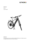
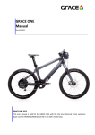
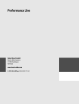
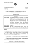
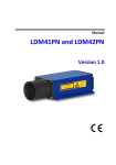
GRACE MX Manual 2013 English GRACE MX Manual 2013 Page | 43 Table of contents Appendices ............................................................................................................................................ 45 Attachments .......................................................................................................................................... 45 Explanation of the symbols ................................................................................................................... 46 Your GRACE MX ..................................................................................................................................... 47 About this user manual ......................................................................................................................... 47 General description of the GRACE MX ................................................................................................ 48 Intended use ........................................................................................................................................ 49 Before the first use ................................................................................................................................ 50 Serial Number ........................................................................................................................................ 50 Scope of delivery ................................................................................................................................... 50 Side reflectors........................................................................................................................................ 52 Rear-view mirror ................................................................................................................................... 52 Insurance sticker ................................................................................................................................... 52 Safety Information and tips ................................................................................................................... 53 Initial operation ..................................................................................................................................... 54 Charging the Battery ............................................................................................................................. 54 Switching the drive on and off .............................................................................................................. 56 Checking tyre pressure .......................................................................................................................... 57 Setting the seat height .......................................................................................................................... 58 Setting the seat angle ............................................................................................................................ 59 Functional description ........................................................................................................................... 60 NuVinci N360 gear system .................................................................................................................... 60 Bosch Drive Unit Motor ......................................................................................................................... 60 Control Computer.................................................................................................................................. 61 Operation unit ....................................................................................................................................... 62 Lighting .................................................................................................................................................. 63 Rock Shox Sektor suspension fork ......................................................................................................... 64 Maintenance ......................................................................................................................................... 65 Prior to any repair work ........................................................................................................................ 65 Dismantling the front wheel.................................................................................................................. 66 Dismantling the rear wheel ................................................................................................................... 67 Page | 44 GRACE MX Manual 2013 Dismantling the gear system ................................................................................................................. 67 Assembling the rear wheel .................................................................................................................... 68 Assembling the gear system .................................................................................................................. 68 Tensioning and aligning the drive belt .................................................................................................. 69 Changing the tyres................................................................................................................................. 71 Mounting and dismounting the pedals ................................................................................................ 72 Changing the brake pads ....................................................................................................................... 73 Wear Parts, Maintenance, vehicle check after a fall………………………………………………………………………...75 Frame paintwork and coating ………………………………………………………………………………………………………...77 Technical information ......................................................................................................................... 78 Frame sizes ............................................................................................................................................ 79 Torques .................................................................................................................................................. 80 Warranty conditions .............................................................................................................................. 81 EC declaration of conformity................................................................................................................. 82 Appendices No. Title: 1 BOSCH* Drive Unit Cruise | Intuvia | Powerpack 300 | Powerpack 400|Charger 2 Instructions for the handling with the belts of the Gates CARBON DRIVE system Type Original instructions Extract of original instructions Attachments No. A B C D E Documentation Delivery checklist GRACE MX service booklet NuVinci N360 Avid (SRAM) Rock Shox Sektor (SRAM) Technical manual Technical manual Technical manual *for GRACE MX 250W Version: www.bosch-ebike.com GRACE MX Manual 2013 Page | 45 Explanation of the symbols To begin with, we would like to familiarize you with the meaning of the attention signs and hazard symbols that you will find in this user manual. Please pay attention to the instructions displayed next to the symbols and follow them without fail. Caution! This attention sign alerts you to a potentially dangerous situation which could result in injury to people in the vicinity and damage to the product or objects. Danger! This symbol indicates an imminent threat of explosion due to improper handling of the battery and the charger for example Information! This sign shows you useful information on how to handle your product. Please note! This symbol indicates that your vehicle could suffer damage. Read the original operating instructions! This symbol refers to further important information in the original user manuals for the HMI control computer, the drive unit, the charger, the battery (BOSCH HMI| Drive Unit 45| Battery Pack| Charger), the circuit (NuVinci N360), the brakes (Avid SRAM), the drive belt (Gates Carbon Drive) and the (SRAM Rock Shox) suspension fork. Page | 46 GRACE MX Manual 2013 Your GRACE MX The GRACE MX guarantees a new kind of movement in the wild. As when the fun of your traditional MRB stops, then the GRACE MX is just getting started. As the first production vehicle worldwide, the GRACE MX combines the Gates CARBON DRIVE, the NuVinci N360 hub and the extremely powerful BOSCH mid-motor, which accelerates the bike up to 45 km/h 1. In this way, going uphill will be just as fast as downhill! The battery, which is inserted from below into the frame is thus protected against stone chippings. The mid-motor, which is rotated to an angle of 45 degrees, allows for a lot of ground clearance and optimal balance on the terrain. About this user manual The content of this user manual refers exclusively to the GRACE MX range of models with the M and L frame sizes in the 2013 model year. Please take the time to read through this entire manual attentively in order to familiarize yourself with the GRACE MX. For maintenance and repair work, do not hesitate to consult your specialised dealer, whose contact data you will find in the delivery checklist (Attachment A). 1 MX S-Pedelec GRACE MX Manual 2013 Page | 47 General description of the GRACE MX 1. Seat 2. Rear light 3. Licence plate holder 4. Seat post 5. Mid-motor 6. Rear wheel 7. Carbon belt 8. Battery housing 9. Side reflector3 9.b Spokes reflector2 1 ² ³ 10. Stem 11. Headlamp 12. Suspension Fork 13. Front wheel 14. Hydraulic disk brakes 15. Crank and pedal 16. NuVinci N360 gear hub 17. Kickstand 1, 3 18. Dynamo² 19. Rear- view mirror³ optional MX- Pedelec MX-Pedelec MX-S-Pedelec Page | 48 GRACE MX Manual 2013 Intended Use Due to its design and its equipment, your GRACE MX Pedelec is designated for the use on paved roads and fortified forest- and field paths. The required safety-related active and passive lighting systems are installed in accordance with the German Regulations (Authorizing the Use of Vehicles for Road Traffic -STVZO). Please install the additionally supplied rear-view mirror and the two reflectors2. The mounting of these components is absolutely required in order to make the bike safe for street traffic according to the German regulations (Road Traffic Act - StVZO) This safety-related equipment must be checked regularly and, if necessary, repaired by a skilled technician. Neither the manufacturer nor the dealer shall be liable for any other use or for failure to comply with the safety-related instructions in this user manual and any resulting damage. Practice the range of things that you can do with your new GRACE MX in a quiet traffic-free area first before venturing into road traffic. Please always bear in mind that other road users might not expect your high speed. The operation of a GRACE MX is not permitted with a trailer. For questions please contact GRACE. Please observe the technical data on page 78 of this manual. ________________________ 1 2 The use of fortified forest and field paths is allowed only with the MX PEDELEC Version Only MX S-Pedelec GRACE MX Manual 2013 Page | 49 Before the first use The GRACE MX Pedelec belongs to the class of electric motor assisted bicycles, also called EPAC (Electric Power Assistant Cycles). The engine power will help only if you exert force on the pedals. Your GRACE MX S-Pedelec is not a bicycle and as a moped, it is subject to the country specific regulations (StVZO). For this reason, the bike has no CE mark, like a motorcycle but rather has a type plate and a vehicle identification number that is registered with the German Federal Bureau of Motor Vehicles and Drivers. Please inform yourself about the regulations in your country that regulate the equipment of mopeds to participation in road traffic. S-Pedelec users must wear a helmet and an insurance sticker must be displayed. You must have a class M driver’s licence and must always keep the certificate of registration with you. Modifications of your GRACE MX S-Pedelec, which result in an increase in motor power and speed, compromise your driving safety and can lead to the loss of your driver’s licence and insurance coverage. Serial number The serial number of your GRACE MX is engraved on the right side of the steering tube. Please write off serial number and keep it in a safe place. Scope of delivery The following items are included in the scope of delivery of the GRACE MX Pedelec: Bosch standard charger Transport locks (2 items) for the brake system Keys (2 items) to secure the battery pack GRACE manual GRACE MX service booklet GRACE MX delivery checklist User manuals and instructions of the supplementary components Page | 50 GRACE MX Manual 2013 Bosch standard charger The scope of delivery includes a Bosch standardcharger to charge the battery. The charger supplied is so compact and light that you can comfortably take it with you. External dimensions: 155x85x55mm, Weight: 860g Transport devices Save the two transport devices for the brake system. They will be a useful aid when repairs are being carried out. Please observe the information in the technical manual Avid (Sram) Keys Two keys are provided in the scope of delivery for the battery lock. Side reflectors Attach the self-adhesive side reflectors supplied in accordance with the assembly instructions on page 52 1 below. 1 Only S-Pedelec GRACE MX Manual 2013 Page | 51 Side reflectors The self-adhesive side reflectors are attached laterally in the battery case. Rear-view mirror Screw the mounting clip of the rear-view mirror with a 4 mm Allen key between the front brake and the HMI unit with two M4 screws to the left handlebar so that it will not skew. 1 In the photo (on the right above) installation of the mirror for right hand traffic is depicted. The mirror must be mounted symmetrically on the right hand side for left hand traffic. 1 Insurance sticker The insurance sticker is attached with two (M4x10) screws and two self-locking nuts to the licence plate holder. 1 1 Only S-Pedelec Page | 52 GRACE MX Manual 2013 Safety information and tips Always check that the lights are working before using your bike. Make sure that you avoid wearing loose clothing on your lower body. In that way, you can prevent clothing from being caught in the belts or between the spokes. Check all wearing parts regularly. These include drive belts, brake pads, brake disks, seals and tyres. Check your GRACE MX regularly for loose spokes as they can lead to instability at high speeds. Modifications of your GRACE MX, which result in an increase in motor power and speed, compromise your driving safety and can lead to the loss of your driver’s licence and insurance coverage. Important tips and information for handling the battery Use only original Bosch batteries, which were approved for the GRACE MX by the manufacturer. The use of other batteries can lead to injuries and the danger of fire. If you don’t wish to use your GRACE MX for an extended period of time (> 1 month), please make sure that the battery is charged to approximately 60%, of capacity, which corresponds to 3 – 4 LEDs on the display. Check the state of charge of the battery after 6 months. If only one LED of the state of charge display is illuminated, then recharge the battery to about 60% capacity. At least 500 full charging cycles are guaranteed for the battery. You can prolong the life span of the battery, if you take good care of it and operate and store it at the correct temperatures. We recommend operating temperatures of between +5 °C and +35 °C and a storage temperature of +20 °C. GRACE MX Manual 2013 Page | 53 Initial operation Charging the battery The battery is mounted on the down tube of your GRACE MX. The battery must be removed from the bracket to charge it. Prior to removing the battery, please make sure that it is switched off. The battery will be loosened and will fold down, if you press simultaneously on both levers of the battery holder. Opening the battery lock will release the battery from the holder and it can fall out. Hold the battery tightly with one hand and open the battery lock with the other hand with a quarter turn of the key. Remove the battery from the holder. Check whether the voltage set on your charger matches the voltage of your power source. (110 volts or 230 volts) Plug the device into the socket of the charger. Then connect the Bosch standard charger to the power supply. Page | 54 GRACE MX Manual 2013 Connect the charger plug to the battery, which is switched off. The charger display will blink. In order to ensure that the battery is fully powered, charge it fully with the charger before you use it for the first time. The battery is fully charged, if all 5 LEDS stay lit up. After the battery is fully charged, the charging process will be interrupted automatically. Disconnect the charger from the power supply and the battery from the charger. The battery will be automatically switched off in the process. The battery can be charged at any time without shortening its life span. Interrupting the charging process will not damage the battery. After the charging process has ended and the battery has been installed, the battery holder must be snapped into place. Please take note of the information of the original instructions for the BOSCH Drive Unit Cruise | Intuvia | PowerPack 300 | PowerPack 400 | Charger page 02: Assembly GRACE MX Manual 2013 Page | 55 Switching the drive on/off Insert the battery into the holder and switch it on using the On/Off button. The drive of the GRACE MX can be switched on and off also on the control computer (see page 61). Switching on the battery also switches on the control unit display. The control unit shows the state of charge of the battery as well as the settings of the drive unit. The pedals of your GRACE MX must not be subject to load when the battery is switched on, as otherwise the capacity of the drive will be limited. If the battery was inadvertently switched on with a load on the pedals, switch it off and then on again without the load. The drive will be activated as soon as you step on the pedals (except for drive assistance mode). The level of assistance depends on the settings of the control unit. As soon as you stop pedalling in normal mode or as soon as you have reached a speed of 25 km/h 1 or 45 km/h 2, assistance from the drive is switched off. The drive will be automatically re-activated as soon as you step on the pedals and the speed is below 25 km/h 1 or 45 km/h 2 To switch the drive off, switch the battery off using the on/off button. 1 2 MX-Pedelec MX S-Pedelec Page | 56 GRACE MX Manual 2013 If no output is requested of the drive for 10 minutes, the battery will automatically switch off to save energy. Checking the tyre pressure Tyres make contact between the wheels and the road. They ensure that the wheels grip the road and that there is traction and absorb small shocks depending on the tyre pressure. Please note the manufacturer’s information on air pressure printed on the side of the tyre. Exceeding the maximum permissible air pressure when you pump your tyres can lead to their bursting. The GRACE MX S-Pedelec is equipped with the following standard tyres: CONTINENTAL Mountain King 2.2 Maximum recommended operating pressure for the front wheel tyre: 4.5 bar (max. 60 psi) Maximum recommended operating pressure for the rear wheel tyre: 4.5 bar (max. 60 psi) Further tyres are also approved by the manufacturer: X-King 2.4 Protection C275 b/b, skw, fb - size: 60-559 X-King 2.2 Protection C275 b/b, skw, fb - size: 55-559 Mountain King 2.4 Protection C287 b/b, skw, fb - size: 60-559 Race King 2.2 Protection C256 b/b, skw, fb - size: 55-599 Contact II C269 b/b reflex, wire - size: 47-559 Cruise Contact C269 b/b, wire- size: 50-599 Hint only for GRACE MX S-Pedelec: Please note when you are replacing tyres that you must use tyres of the same type, dimensions and tread exclusively. GRACE MX Manual 2013 Page | 57 Setting the seat height To set the seat height, loosen the 4 mm Allen screw of the seat post clamp. Adjust the height of the seat to your body measurements by putting your heel on the pedal at its lowest point. To do this, your leg should be fully extended. Make sure that the saddle is aligned horizontally. Pull the seat post out no further than the mark for the minimum plug-in depth. Then tighten the screw of the seat post clamp with a torque of 5 Nm. If you pull the seat post out too far, the seat tube can no longer provide sufficient support for it. The seat post can become loose while you are riding the bike and can damage or break the seat tube. There is a risk of accident and injury! Page | 58 GRACE MX Manual 2013 Setting the seat angle In order to change the angle and the horizontal position of the seat, loosen the two inner Allen screws of the seat post clamp, which are located directly behind the seat post above the rear wheel. Now you can slide the seat back and forth in the clamp guide and adjust the angle. Then re-tighten both screws (see torque table). GRACE MX Manual 2013 Page | 59 Functional description NuVinci N360 shifting system, Rotary handle Gears are shifted on the NuVinci N360 rear wheel hub simply by turning the rotary handle. On the rotary handle display, the gear system is shown as an easily understandable graphic – a hill for deceleration and a plateau for faster speeds. As there are no set gear levels, the exact shifting results from your desired comfort level. In order to ensure the longevity of the NuVinci hub and the rotary handle, we recommend you to activate the shifter only under reduced load. Avoid shifting under full load, or against increased resistance when turning the handle. NuVinci N360 shifting system , Rear wheel hub Gear changes occur within the hub – gently and comfortably via internal shift elements, which are sealed and maintenance-free for life. Read the information on page 13 of the NuVinci N360 Technical Manual: Basic Maintenance and Care Bosch Drive Unit Motor Three sensors calculate frequency and torque. speed, pedalling Page | 60 GRACE MX Manual 2013 Control Computer The display provides you with information concerning: support level, speed, reach, average speed, maximum speed, distance travelled and hour. You can choose between four kinds of drives: Eco, Tour, Sport and Turbo. Please take note of the information of the original instructions for the BOSCH Drive Unit Cruise | Intuvia| PowerPack 300 | PowerPack 400 | Charger, page 08: Product descriptions and Specifications a. b. c. d. e. f. 1. 2. 3. 4. 5. 6. 7. 8. Indicator engine power Indicator assistance level Assistance level indicator Value display Speedometer display Battery state of charge display Button Display function „i“ Lighting button Control computer Holder of the control computer Switch On/Off button of the control computer „Reset“ button USB-Port Protection cap of the USB-Port GRACE MX Manual 2013 Page | 61 Operation Unit 10. Operation Unit 11. Button Display function „i“ on the operating unit 12. Button value decrease/scroll down „-“ 13. Button value increase/ scroll up „+“ 14. Button „Walk” 3. Control Computer 4. Holder control computer 15. Locking of the control computer 16. Blocking screw for the control computer (included in the scope of delivery) 17. Speed sensor 18. Spoke magnet for the speed sensor Page | 62 GRACE MX Manual 2013 Lighting A precise lens system distributes the light of a high-performance LED evenly on the road. In this way, a high intensity of light is achieved and safety is increased in the process. The LED headlamp and the rear light are turned on by pressing the light button on the control unit. 1 Please take note of the information 4 of the original instructions for the BOSCH Drive Unit Cruise| PowerPack 300 | PowerPack 400 | Charger Page 04: Switch on and off the lighting 1 Only S-Pedelec, optional for Pedelec GRACE MX Manual 2013 Page | 63 Rock Shox Sektor suspension fork The Rock Shox Sektor RL suspension fork reliably offers the necessary traction and control on rough terrain. A lock-out function prevents the suspension from movement for efficient pedalling on a flat road. Simply turn the blue knob “compression” at the fork´s crown to the right restriction. The spring stiffness can be adjusted by turning the black knob. The rebound can be adjusted by turning the red knob on the right fork leg. Please take note of the information in the original SRAM user manual for the Rock Shox Sektor RL. Page | 64 GRACE MX Manual 2013 Maintenance Prior to any maintenance work Before performing any maintenance, make sure that the drive is switched off. Please take note of the information of the original instructions for the BOSCH Drive Unit Drive Unit Speed/ control unit Intuvia, page 02 Operation When the front and rear wheels have been disassembled, insert the transport locks provided between the brake pads in order to avoid unintentionally adjusting the distance between them. GRACE MX Manual 2013 Page | 65 Dismantling the front wheel Loosen the quick release mechanism of the axle on the front wheel. To do this, first of all, turn the lever to 180° and snap it into the recess in the axle. The axle can now be unscrewed by means of the lever. Pull the axle to the right and remove it from the fork. While you are doing this, grip the front wheel tightly, release it and move it downwards out of the fork. When the front wheel has been disassembled, insert the transport lock between the brake pads in order to avoid adjusting the distance between them inadvertently. Page | 66 GRACE MX Manual 2013 Dismantling the rear wheel Dismantling the gear system Please follow the guidelines in the manual for the NuVinci N360 on page 11 in the chapter entitled Assembly and Disassembly of the Rear Wheel Loosening the (15 mm) cap nuts will enable the rear wheel to be taken out of the dropout. Slip the drive belt carefully off the sprocket. When the front wheel has been disassembled, insert the brake pad lock between the brake pads in order to avoid inadvertently adjusting the distance between them. Store the rear wheel in such a way as to prevent it from falling down. GRACE MX Manual 2013 Page | 67 Assembling the rear wheel Remove the transport lock. Carefully put the drive belt on the belt sprocket of the rear wheel. Put the rear wheel into the dropout. Position the rear wheel in such a way that the torque support (gib washer) slides into the dropout internally on the right and externally on the left. When you are doing this, please ensure that the brake slides properly between the brake pads. The rear wheel axle must be placed in both dropouts at the same time and the tabs of the torque supports must be in the groove. Attach both hub axle nuts and bolts and tighten them in turn with a (15 mm) spanner and a torque of 30 – 40 Nm. Please see also adjustments torque table page 80. Assembling the gear system Please follow the guidelines in the manual for the NuVinci N360 on page 11 in the chapter entitled Assembly and Disassembly of the Rear Wheel Page | 68 GRACE MX Manual 2013 Tensioning and aligning the drive belt The Gates carbon drive belt is very resilient and durable. However, before and during its installation, extreme caution must be exercised in order to avoid damaging the carbon fibres, which constitute the actual strength of the drive belt. Excessive bending and twisting could cause tears that can lead to a defect in the belt, if it is under great strain. Please take note of instructions for proper handling of the belt of the Gates CARBON DRIVE system If the tension of the drive belt is set too low, this can lead to the drive belt’s slipping on the sprockets. In this way, the carbon fibres on the inside of the drive belt can be damaged. If the drive belt has slipped, you should have it replaced at a qualified specialist workshop. If the tension of the drive belt is too high, bearings and seals in the wheel hub can be damaged. In addition, the whole drive belt is affected by greater loss due to wear and friction. Loosen the 4 Allen head screws at the drop out on the right and left side and the screw of the braking torque support. (SW5) Tighten the belt tensioners on both dropouts with a (10 mm) open-end spanner until the belt has the proper tension. The adjustment screw can be secured by using a wrench SW10. Press down the top of the belt in the middle between the front and rear sprockets with your finger. The belt is correctly tensioned, if it can be pressed down approximately 12 mm with the pressure indicated. GRACE MX Manual 2013 Page | 69 As the tension may vary slightly along the belt, this procedure should be carried out on a belt that is gradually being moved on. To do this, turn the pedal crank one rotation in each case and repeat the measurement process a few times. If the belt tension is too high or too low, continue to adjust it until the measurement result corresponds to the specification. Tighten the four (6 mm) Allen screws of the right and left belt tensioners on the dropouts. Rotate the crank 10 – 15 times backwards and forwards and observe the alignment of the belt in the process. While you are doing so, the belt should only slightly touch the lateral stop (flange) of the rear sprocket or leave a gap of not more than approx. 1 mm. A consistent gap of 0.5 mm is ideal. Wrong Tightening the axle adjustment screw on the dropouts on the drive side or loosening it on the opposite side will guide the belt to be aligned further in the direction of the lateral stop (flange) of the rear sprocket. Adjust the rear wheel, so that the belt is properly aligned as it moves. Right Turn the crank again, check the alignment of the belt and reset it, if necessary. Repeat this step until the alignment of the belt is set correctly. In the process, always adhere to the required belt tension. Page | 70 GRACE MX Manual 2013 Changing the tyres Remove the valve cap of the tube and the knurled nut of the valve nozzle. Bleed the tube by pressing the valve pin. Use a tyre iron to loosen the tyre from the rim. Replace the tyre or the defective tube. If you are putting on a new tyre, change the tube as well! Pull one side of the tyre onto the rim. In the process, please pay attention to the running direction of the tyre that was printed by the manufacturer. Some makes of tyres do not have any rotational direction printed on them. Insert the valve through the valve opening and put the tube into the rim well. GRACE MX Manual 2013 Page | 71 Lever the tyre bead over the rim flange with the installation tools. Pump the tube until the tyre assumes its shape and check to see if it is sitting correctly on the rim. Pump the tyre in accordance with the manufacturer’s specifications (max. 4.5 bar, 60 psi) and check again that the tyre is sitting correctly in the rim. Tighten the knurled nut and screw the valve cap onto the valve. Mounting and dismounting the pedals Lightly grease the threads of the pedal axles and the cranks. Screw in the pedals only loosely by hand. Make sure to bring the parts together in the right angle and do not tilt them. The right pedal has a hand right tread and the left pedal has a left-hand thread on the pedal axle for mounting on the crank. The right pedal is screwed clockwise and the left counter clockwise. Move the crank into a horizontal position so that the pedal points towards the front wheel. Place the wrench (15mm) at the pedal axle and hold the crank firmly on the opposite side. Tighten the pedal with the torque specified by the manufacturer of the crank. Dismounting is performed in reverse order of mounting. Page | 72 GRACE MX Manual 2013 Changing the brake pads Pull the safety clip of the guide pin. Remove the guide pin from the brake calliper with a (2.5 mm) Allen key. Use a flat-tip screwdriver to press the brake pads back into the piston. Pull the H spring with the inserted brake pads out of the brake calliper. GRACE MX Manual 2013 Page | 73 Replace both brake pads, if their total thickness is less than 3 mm per brake pad. Put the H spring with the new brake pads into the brake calliper. Tighten the fastening screw to 1 Nm and then attach the safety clip to the guide pin. Page | 74 GRACE MX Manual 2013 Wearing parts, maintenance and vehicle inspection after a fall Some parts and components on your GRACE MX are susceptible to wear due to their function and must be monitored with particular care for that reason and regularly maintained or replaced. Wearing parts include the following: Tyres Wear to the tyres depends on how the GRACE MX is used and can be very strongly influenced by the rider. The lifespan of a tyre is significantly shortened by sharp braking which leads to the blocking of a tyre and reduces its life span considerably. In addition, tyre pressure should be checked regularly and tyres should be pumped to the level specified by the tyre manufacturer. Brake pads Due to their function, brake pads are susceptible to wear, which is very dependent on how the GRACE MX is used. If the bike is used for sports or for trips on routes with steep inclines, it may be necessary to change the brake pads at frequent intervals. Therefore, it is absolutely essential to check the state of wear of the brake pads regularly. Have them replaced by a dealer, if necessary. Belts The Gates carbon drive belt must always be replaced, if it has been damaged due to improper handling or significant external influences. For instance, a stone, a root or an item of clothing may be seized by the belt and caught between the belt and the sprocket. An incident of that kind can lead to damage being done to the sensitive carbon fibres inside the belt, even if there is no external damage to the belt to be detected. If you suspect that the belt has been damaged, have it replaced in order to avoid the risk of accident or injury. GRACE MX Manual 2013 Page | 75 Replacing belt sprockets in the event of damage The belt sprockets must be changed in any case, if they are damaged by significant external influences. For example, if you hit a rock or a tree root hard with the front belt sprocket when you are riding the bike, it can bend and would have to be replaced in that case. Stones that are drawn in and lodge between the belt and the belt sprocket can distort the teeth of the belt. Teeth can break off in whole or in part. If this is the case, the belt sprocket involved must also be replaced. Whether the belt should be replaced or not must be decided on the basis of the relevant criteria of the previous section. (See 75 Belts.) If a drive, in which all of the components were used for the same length of time, is worn, it is basically recommended that all of the components be replaced, even if only one component has reached the wear limit. Gear cables The Bowden cables of the gears must be regularly maintained and replaced, if applicable. This can be the case, especially if the GRACE MX is often stored outdoors and exposed to the elements. Handles Handlebars and handle coverings are susceptible to wear due to their function and must be replaced regularly where applicable. Handles must always be firmly connected to the handlebars. Lubricants The properties of lubricants change over time. Therefore, all areas to which lubricants are applied must be cleaned regularly and re-lubricated in order to avoid increased wear to the parts and the bearings involved. Handlebars and seat post Both the handlebars and the seat post are subject to severe dynamic stresses, when the bike is being ridden. Therefore, check them regularly for visible external damage and replace them, where applicable. Furthermore, we recommend that these parts be replaced every two years, if your GRACE MX is subject to heavy use. Page | 76 GRACE MX Manual 2013 Frame paintwork and coating The coating on the structural elements of your GRACE MX protects them against corrosion. Check all painted areas regularly for damage and touch them up immediately. This will also maintain the appearance of your bike. When you purchased your GRACE MX, you received a service booklet from your dealer. Please adhere without fail to the inspection intervals entered for your safety and your enjoyment of your bike. (Attachment B) We recommend that your dealer inspects your bike for the first time after you have ridden 100 kilometres. Spokes, brakes, gears and bearings can shift due to settling processes during this running-in phase. Your GRACE dealer is the one, who is most familiar with your bike and has the appropriate tools for the maintenance of your GRACE vehicle. After a fall or an accident on your GRACE MX, you should bring your bike to your dealer for close examination in any event. Damage that was caused by falls or improper handling can only be repaired by your GRACE dealer. Defective parts, particularly forks, handlebars, frames, handlebar stems, seat posts, pedals or crank arms must be replaced immediately due to the danger of breakage. GRACE MX Manual 2013 Page | 77 Technical information Frame Fork Type of engine Torque Batteries Display Headset Brakes Drive: Tyres Battery charger Weight Specific features Range Seat post Handlebars Handles Stem Seat Wheel rims Front wheel hub Pedals Control unit Crank Maximum permissible overall weight Frame geometry Charging time Headlamp Aluminium (6061-T6) Rock Shox Sektor RL Bosch Drive Unit (350 watts) Max. 50 Nm Bosch Li-Ion 36V/11Ah (400 Wh) bzw. 36V/8,2Ah (300Wh) Bosch 4-mode LCD display, background lighting Cane Creek 40 series Avid Elixir 5, 200 mm (in the front) and 180 mm (in the rear) Gates carbon drive with NuVinci N360 hub Continental Mountain King 2.2, 26“ Bosch charger 4 Ah (1 Ah slow) 23 kg 4 drive modes (Eco, Tour, Sport and Turbo) max. 185 km1 / max. 90 km² Truvativ Stylo Truvativ Stylo Velo Truvativ Stylo DDK Rigida Taurus 21 KT Industries Wellgo Bosch HDMI unit Metropolis 120 kg Size M or L About 3,5 hours Busch & Müller ____________________________ 1 MX Pedelec 2 MX S-Pedelec Page | 78 GRACE MX Manual 2013 Frame sizes GRACE MX size M GRACE MX size L A Top tube B Standover height C Inside leg measurement D Seat tube height 585 mm 820 mm 705 mm 475 mm 610 mm 840 mm 730 mm 500 mm GRACE MX Manual 2013 Page | 79 Torques Torques for binding elements on the wheels Rear wheel axle nut Dropout on the frame Braking Torque support droupout left 30 Nm 16 Nm 6 Nm Torques for the handlebars and stem Stem handlebars Stem fork steerer Grip shift Brake lever 5 Nm 5 Nm 2 – 2.5 Nm (according to NuVinci) 2.8 – 3.4 Nm (according to SRAM) Torques for add-on parts Brake callipers Mounting screws for brake pads Post mount adapter Seat clamp Saddle fixation Brake disks 8 – 10 Nm (according to SRAM) 1 Nm 9 – 10 Nm (according to SRAM) 5 Nm 8 Nm 6.2 Nm (according to SRAM) Page | 80 GRACE MX Manual 2013 Warranty conditions Since 01/01/2012 you have been entitled to a warranty period of two years. This period begins when the GRACE MX is handed over by your dealer, who is also the person to contact in the event of a warranty claim. Please store the transfer protocol and the invoice or proof of purchase, as the case may be, in a safe place for the duration of the warranty period. You are entitled to make a warranty claim under the following conditions: If there is a manufacturing, material or information error, If the claimed damage already existed at the time of delivery, If the alteration to the product was not caused by wear due to its function or by ageing or if the damage was not brought about by the failure to use the product in accordance with the regulations. The following items are excluded from the warranty: All wearing parts in accordance with the list of wearing parts itemised under the paragraph on wearing parts, maintenance and vehicle inspection after an accident, unless there is a manufacturing or material error, damage that came about due to competitive use, damage that came about due to improper repair tools and insufficient care, repairs that were made with by means of used parts and damage that originated from the subsequent addition of non-standard equipment and technical modifications. When you purchased your GRACE MX, along with this user manual, you also received the user manuals, the warranty and the warranty conditions from the manufacturers of the supplementary components. (See page 45, Appendices) Please read through those documents attentively as well! GRACE MX Manual 2013 Page | 81 EC Declaration of Conformity 1 Name/address of manufacturer: GRACE GmbH & Co. KG; Wehrmühlenweg 8; 16359 Biesenthal, Germany Product description: EPAC/Pedelec (electric power assisted cycle) This declaration refers exclusively to the Pedelec and exclusively to the status in that market in which it was placed. Furthermore, subsequent mounted parts by the end-user and a subsequent done work on the bike is not accepted by MIFA. The declaration is not valid anymore if the product is modified without agreement. Type designation: GRACE MX (MGE012) Year of manufacture: 2012 The designated product fulfills the European directives: Machinery directive 2006/42/EC Directive for electromagnetic compatibility 2004/108/EC Directive for electrical equipment 2006/95/EC Harmonized standards used and technical standards: DIN EN 15194 : 2009 Pkt. 4.2.5 Cycles-electrical powerassisted cycles - EPAC-Bicycles DIN EN 14766 : 2005 Mountain bicycles - Safety requirements and test methods DIN EN lS0 13849 : 2008 Safety of machinery DIN EN 62079 : 2001 Preparation of instructions – structuring, content and presentation Authorized person: Karl-Heinz Nicolai; Wehrmühlenweg 8; 16359 Biesenthal Biesenthal, 10/09/2012 (place, date) 1 (Legally binding signature of the issuer) board of directors, Karl-Heinz Nicolai MX Pedelec Page | 82 GRACE MX Manual 2013