1
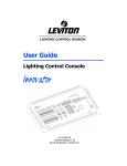
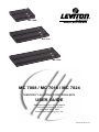
MC 7008
MC 7016
MC 7024
MC 7008 / MC 7016 / MC 7024
MEMORY LIGHTING CONTROLLERS
USER GUIDE
Software Revision 1.00 and above
Document Revised: 8-30-02
Copyright 1994, 2002
Leviton Manufacturing Co., Inc.
Page 1
PK-93130-00-01-1A
Table of Contents
Introduction ......................................................................................................................... 3
Welcome ...................................................................................................................... 3
Specifications ..................................................................................................................... 3
Installation/Setup ............................................................................................................... 3
Power Supply Requirements .................................................................................... 3
Dimmer Equipment Connection ............................................................................... 4
Overview .............................................................................................................................. 4
Front Panel .................................................................................................................. 4
Rear Panel ................................................................................................................... 5
Operation Guide ................................................................................................................. 6
General ........................................................................................................................ 6
Operation Modes ........................................................................................................ 6
Bump Buttons ............................................................................................................. 7
Crossfaders ................................................................................................................. 7
Chases ......................................................................................................................... 7
Master .......................................................................................................................... 7
Blackout ...................................................................................................................... 7
Programming Control Functions ...................................................................................... 8
General ........................................................................................................................ 8
Scene Masters ............................................................................................................ 8
Flash Scenes ............................................................................................................... 8
Chases ......................................................................................................................... 9
Optional DMX512 Installation .......................................................................................... 10
Instructions ............................................................................................................... 10
Troubleshooting ............................................................................................................... 11
Page 2
INTRODUCTION
Welcome
Thank you for your decision to purchase a Leviton-NSI product. The powerful Leviton-NSI Microplex
design involves the electrical marriage of microprocessor technology and digitally controlled multiplexing.
The result is a control package with the flexibility for a variety of applications.
The Leviton-NSI MC 7000 Series Lighting Consoles feature an advanced microprocessor based design
containing many benefits found in today’s personal computers. This technology provides for the option
of adding programmable Memory Scene Masters and Chase effects to the simplicity of a familiar twoscene console.
The Leviton-NSI Microplex technology found in all Leviton-NSI products allows components of your
lighting system to be interconnected by way of standard 3-conductor microphone cables or audio snakes.
Up to 128 individual control signals may be transmitted to dimmer packs through a single microphone
cable and the returned phantom power eliminates the need for AC power cords on Leviton-NSI controllers.
This makes the remote placement of the MC 7000 Series Lighting Console easy and convenient.
Throughout this manual, specifications are listed for the MC 7008 followed by specifications for the MC
7016 in parenthesis () and MC 7024 in brackets [ ].
The Leviton-NSI MC 7000 Series Lighting Console represents our continuing commitment of leading
the industry in defining technological advances for stage lighting.
SPECIFICATIONS
Control Channels:
8/16 (16/32) [24/48]
Dimmers:
16 (32) [48]
Scene Masters (memory):
8 (16) [24]
Chases:
2, 32 steps maximum each
Memory:
Non-volatile EEPROM
(approx. 10 year retention)
Dimmer Outputs:
Leviton-NSI Microplex
DMX512 (optional)
Input Power:
12-15 Volts DC, minimum 200mA
Dimensions (HxWxD):
2 3/4” x 10 5/8” x 9”(2 3/4” x 16 5/8” x 9”)
[2 3/4” x 22 5/8” x 9”]
Weight (approx.):
3.25 lbs. (5.0 lbs.) [6.75 lbs.]
INSTALLATION/SETUP
Power Supply Requirements
The MC 7000 Series Lighting Console requires a source of 12-15 volts DC (at least 200 MA) to operate
satisfactorily. When used with Leviton-NSI dimming equipment, power is provided through the Microplex
microphone cord connection system when connected to the dimmers.
If the console is equipped with the optional DMX512 output and used with DMX512 controlled dimmers
or if the microphone cable length exceeds 100 feet, the external power supply jack can be used to apply
power to the console. Use the power supply provided with the DMX512 option, or call your dealer for
assistance in obtaining a proper supply. Make sure that the plug on any power supply not supplied
through Leviton-NSI is configured so that the center connector is positive.
Page 3
Dimmer Equipment Connection
Connecting the MC 7000 Series Lighting Console to Leviton-NSI dimming equipment is very simple.
You need only connect a single 3 conductor audio cable (standard microphone cable equipped with a 3pin XLR type connector) to either of the jacks marked MICROPLEX on the rear apron of the console. It
doesn’t matter which jack is used, two jacks are provided for convenience. Connect the other end of the
cable to the Leviton-NSI dimming equipment.
Female Microplex
XRL Pin Configuration
2
Male Microplex
XRL Pin Configuration
+15 VDC
1
1 Common
3
Common
2
3
MPX Data
+15 vdc
MPX Data
If the console is equipped with the DMX512 option, connection to the dimming equipment is provided
through the 5-pin XLR type connector located on the rear apron of the console. This connector adheres
to the USITT standard on DMX512 and will support up to 32 (16) dimmer channels with one 3-wire
cable. Since remote power is not provided on this connector, the power supply included with the DMX512
option must be used.
Female DMX512
XLR Pin Configuration
N/C
5
1
Common
N/C
4
2
DMX Data -
3
DMX Data +
OVERVIEW
Front Panel
1. Channel Levels:
These 8 (16) [24] LED’s show the current intensity of each of the console control
channels. The LED’s are inactive whenever the console is in the single scene mode.
2. Scene X:
These 8 (16) [24] slide controls are used to control the intensities of channels 1 8 (1 - 16) [1 - 32] . The overall intensity of the scene created is controlled with the
X Crossfader.
3. Scene Y:
These 8 (16) [24] slide controls are used to control the intensities of channels 1 8 (1 - 8) [1 - 24], channels 9 - 16 (17 - 32) [25 - 48], or scenes 1 - 8 (1 - 16) [1 - 24]
depending upon the consoles current operating mode. The overall intensity of
the scene created is controlled with the Y Crossfader.
4. Bump Buttons:
These 8 (16) [24] buttons are used to bring an individual or group of channels,
depending upon console operating mode, to full intensity.
5. Program Button:
This button is used to program the Scene Masters, the 2 Chases, and the Flash
Scenes. Programming is active when the Program LED is lit.
Page 4
CHANNEL LEVELS
1
1
2
2
4
5
6
7
8
10
9
8
7
6
X5
4
3
2
1
0
10
9
8
7
6
5
4
3
2
1
0
1
9
3
3
2
10
3
11
4
12
5
13
6
14
7
15
CROSSFADERS
X
Y
10
9
8
7
6
5
4
3
2
1
0
1
2
3
4
5
6
7
5
8
16
10
9
8
7
6
Y5
4
3
2
1
0
4
MC 7008
MEMORY LIGHTING CONTROLLER
X
8
Y
PROGRAM 10
9
8
7
2X8
6
8X8
5
4
1 X 16
MODE
1
0
MASTER
LEVEL
10
0
1
2
3
4
10
9
8
7
6
5
4
8
9
10
2
11
12
0
6
TAP SYNC
CHS 1
CHS 2 BLACKOUT
13
BUMP BUTTONS
7
8,9
6. Mode Button:
This button sequences the console through the 3 operating modes. The lit LED
indicates the current mode.
7. Tap Sync:
Repeatedly tapping this button establishes the chase rate.
8. Chase 1:
This button toggles Chase 1 on and off, indicated by the LED.
9. Chase 2:
This button toggles Chase 2 on and off, indicated by the LED.
10. X Crossfader:
This slide control is used to proportionally vary the intensity of Scene X.
11. Y Crossfader:
This slide control is used to proportionally vary the intensity of Scene Y.
12. Master:
This slide control is used to proportionally vary the overall console intensities to
stage except those from the Bump buttons.
13. Blackout:
This button is used to kill all output to stage except from the Bump buttons. The
console is in Blackout whenever the Blackout LED is lit.
Rear Panel
1. Microplex Outputs:
These 2 outputs provide Leviton-NSI’s microphone dimmer connection via a
3-pin XLR type connector. Either connector may be used (1-Male, 1-Female).
2. DMX512:
This optional output is used to provide dimmer control information to dimmers
using this protocol. Its 5 pin Female XLR connector conforms to the USITT
standard.
3. AUX DC Power:
This input jack allows a standard wall transformer rated at 15v DC (at least
200 MA) to provide power to the MC 7000 Series Console.
2
MICROPLEX OUTPUTS
1
3
DMX-512 OUT
AUX POWER IN
PUSH
GND
+ 12-15 VDC
LEVITON MFG. CO., INC.
TUALATIN, OR
TECH SUPPORT 1-800-864-2502
Male
Female
Female
Page 5
OPERATION GUIDE
General
The MC 7000 Series Lighting Console consists of two manual scenes mastered by two split/dipless
crossfaders, a set of bump buttons, two programmable chase effects, a master control and a blackout
button. The console is designed to allow tailoring to your needs. Three modes of operation vary the
function of the Bump buttons from individual Channel Bumps to Flash Scenes, and Scene Y from channels
1 - 8 (1 - 16) [1 - 24], to channels 9 –16 (17 - 32) [25 - 48], or to Memory Scene Masters. In addition, two
Chase Effects allow automated sequencing of lights at varying rates.
To give the user channel intensity feedback, channel intensity LED’s are provided above each of the
Scene X slide controls. These LED’s show relative intensities from all console functions and are not
affected by the Master control or the Blackout button, except single-scene mode.
Operation Modes
The MC 7000 Series Lighting Console has three operating modes: the 2 x 8 (2 x 16) [2 x 24] mode, the
8 x 8 (16 x 16) [24 x 24] mode, and the 1 x 16 (1 x 32) [1 x 48] mode. These modes are selected with the
Mode button. The lit LED indicates the current mode. In standard 2 x 8 (2 x 16) [2 x 24] mode, Scene Y
controls the intensity of channels 1 - 8 (1 - 16) [1 - 24] along with Scene X giving the console two-scene
capability between the scenes. In 8 x 8 (16 x 16) [24 x 24] mode, Scene Y becomes a bank of Scene
Masters, which can be programmed by the user. Each Scene Master has level control of all channels
and operates in a ‘‘pile on’’ fashion giving greatest level precedence. In the 1 x 16 (1 x 32) [1 x 48] mode,
Scene Y becomes channels 9 - 16 (17 - 32) [25 - 48], joining with Scene X to give the console twice the
control channels on one scene. Also in this mode, the bump buttons no longer control individual channels,
but control Flash Scenes, which can be programmed by the user. Each scene can have any combination
of channels so that they can be flashed to maximum intensity at any time. Programming either of the
Chases while in this mode extends each step to 16 (32) [24] channels.
Table 1 — MC 7008 Mode Chart
MODE
SCENE X
SCENE Y
BUMPS
CHASES
CHANNEL LEDS
2 x 8 Mode
Channels 1 - 8
Channels 1- 8
Channels 1- 8
32 Steps x 8 Chan.
Channels 1 - 8
8 x 8 Mode
Channels 1 - 8
Mem Scenes 1 - 8
Channels 1 - 8
32 Steps x 8 Chan.
Channels 1 - 8
1 x 16 Mode
Channels 1 - 8
Channels 9 - 16
Prog for Ch 1 - 16
32 Steps x 16 Chan.
No Function
MODE
SCENE X
SCENE Y
BUMPS
CHASES
CHANNEL LEDS
2 x 16 Mode
Channels 1 - 16
Channels 1- 16
Channels 1- 16
32 Steps x 16 Chan.
Channels 1 - 16
16 x 16 Mode Channels 1 - 16
Mem Scenes 1 - 16
Channels 1 - 16
32 Steps x 16 Chan.
Channels 1 - 16
1 x 32 Mode
Channels 1 - 16
Channels 17 - 32
Prog for Ch 1 - 32
32 Steps x 32 Chan.
No Function
MODE
SCENE X
SCENE Y
BUMPS
CHASES
CHANNEL LEDS
2 x 24 Mode
Channels 1 - 24
Channels 1- 24
Channels 1- 24
32 Steps x 24 Chan.
Channels 1 - 24
24 x 24 Mode Channels 1 - 24
Mem Scenes 1 - 24
Channels 1 - 24
32 Steps x 24 Chan.
Channels 1 - 24
1 x 48 Mode
Channels 25 - 48
Prog for Ch 1 - 48
32 Steps x 48 Chan.
No Function
Table 2 — MC 7016 Mode Chart
Table 3 — MC 7024 Mode Chart
Channels 1 - 24
Page 6
Bump Buttons
Along the bottom edge of the console are 8 (16) [24] momentary push buttons. These buttons are used
to bump each individual channel to full intensity regardless of the Blackout button or the setting of the
Master control. When in the 1 x 16 (1 x 32) [1 x 48] mode, each button no longer controls only one
channel, but can be programmed to control any combination of channels. This makes each button a
Flash Scene. The console is shipped from the factory so that Bump button 1 is programmed for only
channel 1, Bump button 2 for channel 2 and so on. This gives the impression that there is no functionality
change from mode to mode on the bump buttons.
The Bump buttons are also used in programming Flash Scenes and Scene Masters.
Crossfaders
The two Manual Crossfaders are always tied to Scene X and Scene Y. These fade controls allow
crossfading between Scene X and Scene Y with the X Crossfader controlling Scene X and the Y
Crossfader controlling Scene Y. The X Crossfader is at its maximum in the fully up position, while the Y
Crossfader is at its maximum in the fully down position. This configuration allows easy dipless crossfading
providing both crossfaders are moved together. If the crossfaders are not kept in the same position, split
crossfading effects can be accomplished.
Chases
Two Chase effects are provided on the MC 7000 Series Lighting Console. Each can be activated at any
time by simply pressing its associated button. A Chase is active whenever the LED above its Chase
button is lit. Each Chase has a maximum of 32 steps and each step can have any combination of
channels. When programming in the 2 x 8 (2 x 16) [2 x 24] and the 8 x 8 (16 x 16) [24 x 24] modes each
step has 8 (16) [24] channels of control, when in the 1 x 16 (1 x 32) [1 x 48] mode each step has 16 (32)
[48] channels of control.
Once a Chase is programmed, it will remain with the same number of channels it was programmed in,
regardless of mode during playback. This can add expanded channel capabilities to the other two modes.
For example, a 7016 chase could be programmed in the 1 x 32 mode to control only channels 17 - 32 for
special effects, and then the console could be run in the 16 x 16 mode to make memory scenes available,
and the Bump buttons could be used to create area and special lighting on channels 1 - 16.
The Chase Rate is set by repeatedly tapping the Tap Sync button at the rate desired. The Chases will
continue to run at the rate of the last two taps until another set of taps is seen. This allows easy
synchronization with music or other timed events.
Master
The Master slide control provides proportional level control over all console functions to stage with the
exception of the Bump buttons. For example, whenever the Master slide control is at minimum all stage
outputs will be at zero except for any resulting from a Bump button, if the Master is at 50% all stage
outputs will be at only 50% of their current console settings except for any resulting from a Bump button
and if the Master is at full all stage outputs will follow the console settings.
Blackout
The Blackout button is used to disable all outputs to stage with the exception of those resulting from a
Bump button. This provides for quick dousing of stage levels or for creating solo effects when used in
conjunction with the Bump buttons. Blackout is active whenever the Blackout LED is lit.
Page 7
PROGRAMMING CONTROL FUNCTIONS
General
The functions that can be programmed on the MC 7000 Series Lighting Console are the two Chases,
the Scene Masters in the 8 x 8 (16 x 16) [24 x 24] mode and the Flash Scenes in the 1 x 16 (1 x 32) [1
x 48] mode. To initiate programming, first tap the Program button. This will light the Program LED indicating
that the program mode is active. Then tap the function button to be programmed. All programming is
stored in non-volatile memory, which retains information for at least 10 years, even when power is
removed.
Scene Masters
When in the 8 x 8 (16 x 16) [24 x 24] mode, the Scene Masters can be programmed for later recall. First
create the desired scene on Scene X. Neither the level of the Master or the X Crossfader or the state of
the Blackout function have any effect on the programmed levels from Scene X. Once the scene is
satisfactory, enter the program mode by tapping the Program button. Then tap the Bump button under
the Scene Y slide control that is to be used as the Scene Master. The Scene Master is now programmed
and the Program mode is automatically released. Once programmed, the Scene Master is ready for
immediate use. To playback the scene, use the Y fader associated with the bump button used to program
that scene master.
EXAMPLE: Program the fifth Scene Master with channels 1 and 6 at full and 7 and 8 at 50%.
1. Lower all Scene X slide controls to minimum.
2. Raise Scene X slide controls 1 and 6 to maximum.
3. Raise Scene X slide controls 7 and 8 to 50%.
4. Tap the Program button. The Program LED should now be lit.
5. Tap Bump button 5.
Flash Scenes
Since there are only 8 (16) [24] Bump buttons, channels 9 - 16 (17 - 32) [25 - 48] cannot be accessed for
bumping in the 1 x 16 (1 x 32) [1 x 48] mode. For this reason the Bump buttons can be programmed as
Flash Scenes to access the upper channels whenever in this mode. Flash Scenes consist of any combination
of fully on or fully off channels. Flash Scenes are programmed with both Scene X and Scene Y slide
controls. Simply raise those sliders that are desired on to maximum and those desired off to minimum.
Next, tap the program button to turn on the Program function. Finally, tap the Bump button to be programmed.
Once programmed, the Flash Scene is ready for immediate use.
EXAMPLE: Program Bump button 8 to flash channels 3, 15, 23 and 24 on a Cat. No. 7016.
1. Lower all Scene X and Scene Y slide controls to minimum.
2. Raise Scene X slide controls 3 and 15 to maximum.
3. Raise Scene Y slide controls 7/23 and 8/24 to maximum.
4. Tap the Program button. The Program LED should now be lit.
5. Tap Bump button 8.
EXAMPLE: Program Bump button 8 to flash channel 3 and 15 on a Cat. No. 7008.
1. Lower all Scene X and Scene Y slide controls to minimum.
2. Raise Scene X slide control 3 to maximum.
3. Raise Scene Y slide control 7/15 to maximum.
4. Tap the Program button. The Program LED should now be lit.
5. Tap Bump button 8.
Page 8
Chases
Each of the two Chase functions can be programmed to include any channel in any step up to a maximum
of 32 steps per Chase. To initiate Chase programming, first tap the Program button so that the Program
LED is lit. Then tap the Chase button of the Chase to be programmed and the LED under the chase
button should start flashing. The console is now ready to program the first step of the chase. Use the
Scene X slide controls to indicate which channels should be on or off by either raising them to full or
lowering them to minimum. Once set, tap the Program button again to store the step. The console is
now ready to program the second step of the chase. Continue programming steps, up to 32, until the
chase is complete. Tapping the Blackout button exits the chase programming. Programming will be
automatically exited if more than 32 steps are attempted.
If the console is in the 1 x 16 (1 x 32) [1 x 48] mode, Scene Y can be used to include the channels
controlled by these sliders in the Chase program. Follow the same procedure explained above, but
include the Scene Y channels into each step programmed.
EXAMPLE: Program a 4-step chase consisting of channels 1 - 4 into Chase 2.
1. Tap the Program button. The Program LED should now be lit.
2. Tap Chase button 2. Chase 2 LED should now be flashing.
3. Move all Scene X slide controls to minimum.
4. Raise Scene X slider 1 to maximum.
5. Tap Program button.
6. Lower Scene X slider 1 to minimum and raise 2 to maximum.
7. Tap Program button.
8. Lower Scene X slider 2 to minimum and raise 3 to maximum.
9. Tap Program button.
10. Lower Scene X slider 3 to minimum and raise 4 to maximum.
11. Tap Program button.
12. Tap the Blackout button.
EXAMPLE: Program a 4-step chase consisting of channels 9 - 12 into Chase 2 on a MC 7008.
1. Tap the Mode button until the LED below 1 x 16 is lit.
2. Tap the Program button. The Program LED should now be lit.
3. Tap Chase button 2. Chase 2 LED should now be flashing.
4. Move all Scene X and Scene Y slide controls to minimum.
5. Raise Scene Y slider 1/9 to maximum.
6. Tap Program button.
7. Lower Scene Y slider 1/9 to minimum and raise 2/10 to maximum.
8. Tap Program button.
9. Lower Scene Y slider 2/10 to minimum and raise 3/11 to maximum.
10. Tap Program button.
11. Lower Scene Y slider 3/11 to minimum and raise 4/12 to maximum.
12. Tap Program button.
13. Tap the Blackout button.
Page 9
EXAMPLE: Program a 4-step chase consisting of channels 17 - 20 into Chase 1 of a MC 7016.
1. Tap the Mode button until the LED next to 1 x 32 is lit.
2. Tap the Program button. The Program LED should now be lit.
3. Tap Chase button 1. Chase 1 LED should now be flashing.
4. Move all Scene X and Scene Y slide controls to minimum.
5. Raise Scene Y slider 1/17 to maximum.
6. Tap Program button.
7. Lower Scene Y slider 1/17 to minimum and raise 2/18 to maximum.
8. Tap Program button.
9. Lower Scene Y slider 2/18 to minimum and raise 3/19 to maximum.
10. Tap Program button.
11. Lower Scene Y slider 3/19 to minimum and raise 4/20 to maximum.
12. Tap Program button.
13. Tap the Blackout button.
If the Chase is active when programming is initiated, the Chase will halt during programming and resume
with the new programming when completed. If the Chase was not active, it will not be running when
programming is complete.
OPTIONAL DMX512 INSTALLATION
Instructions
Following are the instructions for field installation of the DMX512 option (OPT-07512-01).
REMOVE COVER PLATE
AND INSTALL CONNECTOR
1. Remove screws from bottom
of console and remove
bottom cover.
2. Remove 2 screws and remove
DMX512 option cover plate.
3. Insert DMX512 connector into
opening and install hardware
provided.
1
NOTCH OR DIMPLE
5 PIN CONNECTOR
INSTALL 3695 IC HERE
4. Connect cable from DMX512
connector to 5-pin connection
as shown.
EPROM
5. Install 3695 IC into 8-pin
socket as shown, be sure to
observe the location of the
notch or dimple. Be sure legs
go in straight and not bent.
6. Replace bottom cover of unit.
Note: DMX512 will activate
automatically. Microplex and
DMX512
are
transmitted
concurrently and both may be used at the same time.
Page 10
BOTTOM VIEW
BACK OF PC BOARD EXPOSED
WITH BOTTOM OF UNIT REMOVED
TROUBLESHOOTING
Symptom
Check List
Channel Level LED’s do not respond.
1. Check to see if the 1 x 16 (1 x 32) [1 x 48] mode
is selected. Since all channels cannot be viewed,
the LED’s are disabled in this mode.
Chase functions do not work.
1. Make sure a rate has been established with the
Tap Sync button. The rate is indicated by the
flashing LED located directly above the Tap Sync
button.
Lights on stage do not operate even
though Channel Level LED’s do.
1. Check that the Master slide control is not set at
its minimum position and the Blackout LED is not ON.
Scene X or Scene Y slide controls have
no effect on channel levels.
1. Make sure that the X or Y Crossfader is not in its
minimum position.
Stage lights are ON, but will not respond
or respond erratically.
1. Make sure the dimmer packs are programmed
correctly. Dimmer packs programmed for channels
higher that 32 (16) will not respond to the controller.
2. Check for a bad control cable by replacing it.
3. The dimmer pack may be defective.
4. If the microphone cable is in excess of 100 feet,
heavier gauge (18 ga.) cable or an additional
power supply located at the console may be
necessary because of power loses over the length
of the cable.
Erratic operation when a particular
fade is up.
1. Defective fader.
Channel comes ON when adjacent
fader is up.
1. Defective fader.
Page 11
LIMITED TWO YEAR WARRANTY AND EXCLUSIONS
Leviton warrants to the original consumer purchaser and not for the benefit of anyone
else that this product at the time of its sale by Leviton is free of defects in materials
and workmanship under normal and proper use for two years from the purchase
date. Leviton’s only obligation is to correct such defects by repair or replacement, at
its option, if within such two year period the product is returned prepaid, with proof of
purchase date, and a description of the problem to Leviton Manufacturing Co.,
Inc., Att: Service Department, 20497 SW Teton Ave., Tualatin, Oregon 97062. All
products returned to Leviton-NSI must have factory authorization for return prior to
shipping. The purchaser is responsible for completing and mailing to Leviton, within
15 days of purchase, the warranty registration card enclosed with each product.
This warranty excludes and there is disclaimed liability for labor for removal of this
product or reinstallation. This warranty is void if this product is installed improperly
or in an improper environment, overloaded, misused, opened, abused, or altered in
any manner, or is not used under normal operating conditions or not in accordance
with any labels or instructions. There are no other or implied warranties of any kind,
including merchantability and fitness for a particular purpose, but if any implied
warranty is required by the applicable jurisdiction, the duration of any such implied
warranty, including merchantability and fitness for a particular purpose, is limited to
two years. Leviton is not liable for incidental, indirect, special, or consequential
damages, including without limitation, damage to, or loss of use of, any equipment,
lost sales or profits or delay or failure to perform this warranty obligation. The remedies
provided herein are the exclusive remedies under this warranty, whether based on
contract, tort or otherwise.
For Technical Assistance Call:
1-800-864-2502
www.nsicorp.com
www.leviton.com
Page 12
PK-93130-00-01-1A