1
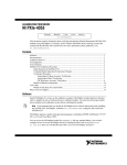
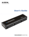
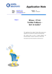
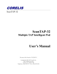
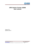
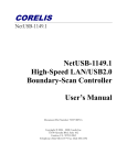
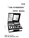
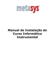
CALIBRATION PROCEDURE
NI TB-4353
Français
Deutsch
ni.com/manuals
This document contains information about verifying National Instruments PXIe-4353 modules
using NI-DAQmx 9.3 and later. It also contains information about verifying systems that include
both the NI PXIe-4353 and TB-4353. For more information about calibration, visit ni.com/
calibration.
Contents
Software Requirements............................................................................................................. 1
Documentation Requirements .................................................................................................. 2
Calibration Interval................................................................................................................... 2
Test Equipment......................................................................................................................... 3
Test Conditions......................................................................................................................... 4
TB-4353 Calibration Procedure................................................................................................ 4
Initial Setup....................................................................................................................... 5
Verifying Module Operating Temperature Changes ........................................................ 7
Terminal Block Temperature Accuracy Verification ....................................................... 7
Limits........................................................................................................................................ 13
Terminal Block Verification Test............................................................................................. 13
Where to Go for Support .......................................................................................................... 13
Software Requirements
Install NI-DAQmx 9.3 or later on the calibration computer. You must have the proper module
driver installed on the calibration system before calibrating the module.
Note NI recommends that you install the NI-DAQmx driver software before
physically installing the NI PXIe-4353. NI-DAQmx, available at ni.com/
downloads, configures and controls the NI PXIe-4353.
NI-DAQmx supports a number of programming languages, including LabVIEW,
LabWindows™/CVI™, C/C++, C#, and Visual Basic .NET.
You can access the NI-DAQmx header file, NIDAQmx.h, like any standard library. To find
examples for using the NI-DAQmx driver, go to ni.com/info and enter the Info Code
NIDAQmxExLoc. There you will find the topic Where Can I Find NI-DAQmx Examples? that
provides example information.
Documentation Requirements
The following documents are your primary references for writing your calibration utility with
NI-DAQmx. You can download the latest version of these documents from the NI Web site at
ni.com/manuals.
•
The NI PXIe-4353 and TB-4353 Installation Guide and Terminal Block Specifications
provides instructions for installing and configuring the NI PXIe-4353 module and TB-4353
accessory.
•
The NI PXIe-4353 User Manual describes how to use the NI PXIe-4353.
•
The NI PXIe-4353 Specifications lists the specifications for the NI PXIe-4353.
•
The NI PXIe-4353 Calibration Procedure provide calibration information for the
NI PXIe-4353.
•
The CAL-4353 Specifications lists the specifications for the CAL-4353.
•
The NI-DAQmx Help includes information about creating applications that use the
NI-DAQmx driver.
•
The NI-DAQmx C Reference Help includes information about the functions in the driver.
Calibration Interval
National Instruments recommends a calibration interval of one year for the NI TB-4353.
You should adjust the recommended calibration interval based on the measurement accuracy
demands of your application.
2 | ni.com | NI TB-4353 Calibration Procedure
Test Equipment
National Instruments recommends that you use the instruments in Table 1 for calibrating an
NI PXIe-4353 module.
Table 1. Recommended Equipment
Equipment
Recommended Model
Requirements
Thermocouple
Calibrator
Ectron 1140A
If this instrument is unavailable, use a high
precision thermocouple source with an
accuracy of at least 0.08 °C and an output
impedance of ≤10 Ω.
Thermocouple Wire
TT-E-24-SLE-100
E-type SLE 24 AWG, 20 to 30 meters
Thermocouple
Connector
Omega P/N: SMPW-E-M
E-type, must fit the output terminal of the
thermocouple calibrator
Thermocouple Barrier
Strips
Omega P/N: BS16A (x4)
32 channels
Thermocouple Barrier
Strip Jackets
Omega P/N: BSJ-E (x6)
E-type, 32 channels
Thermocouple Spade
Lugs
Omega P/N: SLCH-20 (x4),
SLCO-20 (x4)
64 lugs of Chromel, 64 lugs of Constantan to
match the E-type wires
Spade-Lug Crimping
Tool
Omega P/N: CRIMPING
TOOL-P
Must effectively crimp the spade lugs with the
24 AWG wire
PXI Express Chassis
NI PXIe-1062Q
Accessory
TB-4353
This accessory is used for system verification
Calibrated
NI PXIe-4353 Module
NI PXIe-4353
The module must be verified to be within its
specifications
—
NI TB-4353 Calibration Procedure | © National Instruments | 3
Test Conditions
The following setup and environmental conditions are required to ensure the module meets
published specifications.
•
Keep connections to the module as short as possible. Long cables and wires act as antennas,
picking up extra noise that can affect measurements.
•
Verify that all connections to the device are secure.
•
Maintain an ambient temperature of 23 °C ±5 °C. The module temperature will be greater
than the ambient temperature.
•
Keep relative humidity below 80%.
•
Allow a warm-up time of 15 minutes to ensure that the measurement circuitry of the
NI PXIe-4353 and TB-4353 are at a stable operating temperature.
•
Use shielded wire for all cable connections to the module. Use twisted-pair wire to
eliminate noise.
•
Ensure that the PXI Express chassis fan speed is set to HIGH, that the fan filters are clean,
and that the empty slots contain filler panels. For more information, refer to the Maintain
Forced-Air Cooling Note to Users document available at ni.com/manuals.
•
To correctly verify the TB-4353, the NI PXIe-4353 must be currently verified to be within
the product specifications. If they are not, verify the NI PXIe-4353 before verifying the
TB-4353. Refer to the NI PXIe-4353 Calibration Procedure to verify the NI PXIe-4353 as
needed.
TB-4353 Calibration Procedure
This section provides instructions for verifying the performance of a TB-4353. The system-level
calibration process consists of the following steps:
1.
Initial Setup—Configure the NI PXIe-4353 and the TB-4353 in NI-DAQmx.
2.
Verifying Module Operating Temperature Changes—Verify that the current module
operating temperature will not cause you to incorrectly calibrate your module.
3.
Terminal Block Temperature Accuracy Verification—Verify the existing operation of the
NI PXIe-4353 with the TB-4353. This step confirms whether the module and terminal
block are operating within the specified range or require adjustment.
4.
Adjustment—If the system falls within the desired specifications, you can skip this step.
If the NI PXIe-4353 does not fall within the desired specifications, verify that the
NI PXIe-4353 passed verification in the NI PXIe-4353 Calibration Procedure document
and that all test conditions are followed.
If the NI PXIe-4353 passed verification and the test conditions are valid, return the
TB-4353 to the factory for analysis.
5.
Reverification—Repeat the verification procedure to ensure that the module is operating
within the published specifications after adjustment.
4 | ni.com | NI TB-4353 Calibration Procedure
Initial Setup
You must configure the module in Measurement & Automation Explorer (MAX) to
communicate with NI-DAQmx.
Complete the following steps to configure a module in MAX. Refer to the NI PXIe-4353 and
TB-4353 Installation Guide and Terminal Block Specifications for complete installation
instructions.
Note You can also perform the self-test operation programmatically, using the
DAQmx Self-Test Device VI or the equivalent C/.NET functionality.
1.
Install the NI-DAQmx driver software.
Caution
Always have the PXI Express chassis powered off when inserting a
module.
2.
Insert the calibrated NI PXIe-4353 into an available slot in the PXI Express chassis.
Caution Make sure the TB-4353 has three keys installed in its connector and that
none of the keys are loose. The keying locations are shown in Figure 1. If any of the
three keys are missing or loose, refer to the Where to Go for Support section for
assistance in returning the terminal block to NI.
NI TB-4353 Calibration Procedure | © National Instruments | 5
Figure 1. TB-4353 Connector Key Locations
1
1
1
Key Locations
3.
Attach the TB-4353 to the NI PXIe-4353.
4.
Power on the chassis.
5.
Launch MAX.
6.
Expand Devices and Interfaces to confirm that MAX detects the module and terminal
block. The terminal block should appear beneath its associated module.
7.
Right-click NI PXIe-4353 and select Self-Test to ensure that the module is working
properly.
6 | ni.com | NI TB-4353 Calibration Procedure
Verifying Module Operating Temperature Changes
A module operating temperature greater than ±10 °C since the previous calibration adjustment
can cause you to incorrectly calibrate your module. The onboard temperature sensor on the
module can be used to verify that this condition does not exist. Complete the following steps to
compare the current module temperature to the temperature measured during the last calibration.
Note You can also query the temperatures programmatically, using the DAQmx
Calibration Info property node or the equivalent C/.NET functionality.
1.
Launch MAX.
2.
Select My System»Devices and Interfaces»Chassis 1»NI PXIe-4353.
3.
Click the Calibration tab.
If the difference between the current operating temperature and the operating temperature
from the last calibration adjustment is greater than 10 °C, the limits in the calibration tables
are not valid.
Note The temperature reading returned by the module is an internal temperature.
Typically, the internal temperature is approximately 10 °C warmer than the ambient
temperature.
If the module temperature difference is outside the maximum range, you should change the
system so that the operating temperature will be closer to the temperature recorded during the
last calibration adjustment.
Terminal Block Temperature Accuracy Verification
System-level verification determines how well the module and terminal block meet the
temperature accuracy specifications. By completing the following procedure, you can determine
the terminal block drift over time. Table 3, in the Terminal Block Verification Test section,
shows the test points and test limits for the terminal block. Throughout the temperature accuracy
verification process, use Table 3 to determine if the module is operating within its specified
range.
1.
Use the single thermocouple wire, the spade lugs, the spade-lug crimping tool, and the
mini-thermocouple connector to make a wire with a compensated mini-thermocouple
connector on one end and multiple spade-lug leads on the other end as shown in Figure 2.
Note Compensated spade-lug colors in Figures 2, 3, and 5 are for illustration
purposes only and are used to easily differentiate + and –.
NI TB-4353 Calibration Procedure | © National Instruments | 7
Figure 2. Mini-Thermocouple Connector to Compensated Spade-Lug Assembly
–
+
E–
E+
1
1
2.
Total of 32 Terminals
Using the thermocouple wire and the remaining spade lugs, make 32 cables with bare leads
on one end and the compensated spade lugs on the other end as shown in Figure 3.
Figure 3. Thermocouple Compensated Spade-Lug Assembly
E+
E+
E–
8 | ni.com | NI TB-4353 Calibration Procedure
E–
3.
Assemble the barrier strips and barrier strip jackets as indicated by the manufacturer while
referring to Figure 4.
Figure 4. Barrier Strip Jacket Installation
3
–
2
+
2
1
–
+
1
Barrier Strip
2
Barrier Strip Jacket
3
Terminal Screws
NI TB-4353 Calibration Procedure | © National Instruments | 9
4.
Using the assembled barrier strips and cables from steps 1 through 3, make the connections
shown in Figure 5 between the thermocouple calibrator and the 32 channels of the
TB-4353.
Figure 5 shows wiring for eight channels. Make similar connections for the
24 remaining channels.
Note
+ – + – + – + – + – + – + – + –
TC24 TC25 TC26 TC27 TC28 TC29 TC30 TC31
+ – + – + – + – + – + – + – + –
TC16 TC17 TC18 TC19 TC20 TC21 TC22 TC23
+ – + – + – + – + – + – + – + –
TC8 TC9 TC10 TC11 TC12 TC13 TC14 TC15
+ – + – + – + – + – + – + – + –
1
TC0 TC1 TC2 TC3 TC4 TC5 TC6 TC7
Figure 5. Thermocouple Calibrator to TB-4353 Connections
2
–
+
3
Not to Scale
1
TB-4353
2
Barrier Strip Assembly
10 | ni.com | NI TB-4353 Calibration Procedure
3
Thermocouple Calibrator
5.
Place the barrier strip section into an otherwise empty box. Close the lid and leave only a
small opening for the wires to enter and exit the box as shown in Figure 6. This setup
isolates the barrier strip from air currents and rapid temperature transients. Refer to
Figure 6.
Figure 6. Rapid Temperature Transient Isolation Box
3
1
1
6.
One Channel In
2
2
Empty Box Containing Barrier Strip
3
32 Channels Out
Power on the thermocouple calibrator and set the thermocouple type to E-type.
7.
Ensure that the cover is installed properly on the terminal block.
8.
Wait the warm-up time required by the thermocouple calibrator or 15 minutes, whichever
is longer.
9.
Create and configure an AI Temp Built-In Sensor channel for CJC channel _cjtemp0 on
the NI PXIe-4353.
10. Set the timing mode to 1 (High Resolution).
11. Configure the timing properties for a finite acquisition with a sample clock rate of 1 S/s and
30 samples per channel.
12. Start the temperature acquisition.
13. Average the temperature data and record this value as cjc_temp0.
14. Set the thermocouple calibrator output to CJC_temp0. This ensures that during the
thermocouple measurements, the input channel measures very close to 0 V, which
eliminates gain errors in the NI PXIe-4353.
15. Create and configure an AI Temp TC channel for the NI PXIe-4353 for all 32 channels.
16. For every sample, enable autozero and disable open thermocouple detection for the
NI PXIe-4353.
17. Set the timing mode to 1 (High Resolution).
18. Configure the timing properties for the temperature acquisition according to Table 2.
19. Start the acquisition.
NI TB-4353 Calibration Procedure | © National Instruments | 11
20. Acquire the temperature data.
Make sure the thermocouple calibrator and NI PXIe-4353 are completely
settled at the desired temperature setting before acquiring data. When using the
Ectron 1140A, wait at least 300 ms for the system to settle before issuing the start task
function to the NI PXIe-4353.
Note
21. Average the temperature values separately for each channel that you acquired and record the
average as Temperature_Ch_x (where x is the number of the particular channel). Subtract
CJC_temp0 from each average. Record the difference as Temperature_error_Ch_x (where x
is the number of the particular channel). Compare the resulting errors for each channel to the
Upper Limit and Lower Limit values in Table 3. If the result is between these values for each
channel, the terminal block passes.
22. Clear the acquisition.
If the verification procedure determines that the TB-4353 is outside of the specifications, refer
to the Where to Go for Support section for assistance in returning the terminal block to NI.
Table 2. Configuration Values
Configuration
Value (TC)
Physical Channel Name
Dev1/ai0:31
Sample Mode
Finite samples
Sample Clock Rate
1 S/s
Samples per Channel
30
Measurement Type
Thermocouple
Max Input Limit
100.0
Min Input Limit
0.0
Units
°C
Thermocouple Configuration
N/A
Thermocouple Type
E
CJC Source
Built-in
CJC Value
0.0
12 | ni.com | NI TB-4353 Calibration Procedure
Limits
Table 3 lists the specifications that the NI PXIe 4353 and TB 4353 system should meet if it has
been one year between calibrations. The following definitions describe how to use the
information from Table 3:
•
Test Point—The temperature value that is input for verification purposes.
•
1-Year Limits—Contains the Upper Limits and Lower Limits for the test point value. That
is, when the module is within its 1-year calibration interval, the test point value should fall
between these upper and lower limit values.
Terminal Block Verification Test
Table 3 contains the terminal block verification test limits.
Table 3. Terminal Block Verification Test Limits with Autozero Enabled
(Timing Mode 1, High Resolution)
Range (°C)
TC Type
Minimum
Maximum
Test Point
Value (°C)
E
–270
1000
CJC_temp0
1-Year Limits (°C)
Lower Limit
Upper Limit
–0.33
0.33
Where to Go for Support
The National Instruments Web site is your complete resource for technical support. At ni.com/
support you have access to everything from troubleshooting and application development
self-help resources to email and phone assistance from NI Application Engineers
National Instruments corporate headquarters is located at 11500 North Mopac Expressway,
Austin, Texas, 78759-3504. National Instruments also has offices located around the world to
help address your support needs. For telephone support in the United States, create your service
request at ni.com/support and follow the calling instructions or dial 512 795 8248. For
telephone support outside the United States, visit the Worldwide Offices section of ni.com/
niglobal to access the branch office Web sites, which provide up-to-date contact information,
support phone numbers, email addresses, and current events.
CVI, LabVIEW, National Instruments, NI, ni.com, the National Instruments corporate logo, and the Eagle logo are trademarks of National
Instruments Corporation. Refer to the Trademark Information at ni.com/trademarks for other National Instruments trademarks. The mark
LabWindows is used under a license from Microsoft Corporation. Windows is a registered trademark of Microsoft Corporation in the United States
and other countries. Other product and company names mentioned herein are trademarks or trade names of their respective companies. For patents
covering National Instruments products/technology, refer to the appropriate location: Help»Patents in your software, the patents.txt file on
your media, or the National Instruments Patents Notice at ni.com/patents. Refer to the Export Compliance Information at ni.com/
legal/export-compliance for the National Instruments global trade compliance policy and how to obtain relevant HTS codes, ECCNs, and
other import/export data.
© 2012 National Instruments. All rights reserved.
373773B-01
Aug12