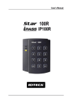
1
Quick Installation Guide
Quick Installation Guide
1. IMPORTANT SAFETY INSTRUCTIONS
The description below is to keep user’s safety and prevent any product damage. Please fully
read these instruction and use the product properly.
Danger: This symbol indicates that incorrect handling of the product may
result in serious injury or death.
Warning: This symbol indicates that incorrect handling of the product may
result in injury or property damage.
Cautions about Power
- Only use the standard voltage (DC +12V/ 350mA).
- If the product emits smoke or smells, stop using the product. Unplug the product from DC power
source and contact nearest service center.
Cautions about Installation
- Do not install the product in humid, dust (metallic dust) and sooty place.
- Do not install the product in a place subject to high or low temperature and high humidity
- Do not install the product with tools such as driver in hand when power has been supplied.
Cautions about Usage
- Do not drop liquid like water and give a shock severely.
- Do not place magnetic objects near the product.
- Do not replace the wiring cables installed by experts.
- Do not use the product near direct sunlight and heating apparatus.
- If you want to relocate the installed product, turn power off and then move and reinstall it.
- Do not use the product near flammable spray or objects.
- Do not disassemble, repair or modify the product by yourself. If the product needs service or repair,
contact nearest service center.
- If liquid has been spilled on the product, unplug it and contact nearest service center.
Cautions about Cleaning
- Do not clean the product with water. Clean gently with dry cloth or tower
- Do not use chemicals such as benzene, thinner or acetone for cleaning.
Jun. 2011 Copyright © IDTECK Co., Ltd.
Quick Installation Guide
2. IDENTIFYING SUPPLIED PARTS
Please unpack and check the contents of the box.
Main Unit
(1ea)
3.5*40 Screw
(4ea)
Wall Mount
(1ea)
3.5*12 Screw
(4ea)
Anchor Bolt
(4ea)
O-Ring
(5ea)
User’s Manual
(1copy)
Cable & Diode
Cable(4 ea), Diode(2 ea)
Master Card
(1ea)
3.FRONT PANEL DESCRIPTION
Figure: Front Panel
Jun. 2011 Copyright © IDTECK Co., Ltd.
Quick Installation Guide
4. INSTALLATION
1. Tear off page on the back this manual and use the provided template to drill two 6-32 holes and one
1/2" hole on the proper location of the wall to mount the Wall Mount bracket as shown below.
(If the gang box is already installed on the wall then skip this step.)
2. Using 2 screws, install wall mount to the wall.
※CAUTIONS
Before mounting the STAR 100R unit to the Wall Mount bracket, operational testing of the unit
should be completed, as the locking pins will lock the unit to the Wall Mount. Removing the unit
from the Wall Mount bracket after they have been installed together may cause damages to the
bracket and render its effectiveness.
2. Insert 5 O-rings to the wall mount as indicated, then route the cable of the main unit through the
center hole and push the main unit to wall mount to lock the main unit and make sure that the main
unit is locked with wall mount.
Jun. 2011 Copyright © IDTECK Co., Ltd.
Quick Installation Guide
5. WIRING COLOR TABLE
I/O PORT NAME
2PIN
Main Power(+12V)
Power Ground
10PIN
Door Relay(NC)
SIGNAL NAME
(J1)
DC +12V
GND
(J2)
NC(1)
Door Relay(COM)
Door Relay(NO)
Alarm Relay(NC)
Alarm Relay(COM)
Alarm Relay(NO)
Exit Button
Door Sensor
Aux Input 1
Aux Input 2
7PIN
Wiegand Data0
Wiegand Data1
TTL Output
Chime Bell Output
Aux Input 3
RESERVED
RESERVED
3PIN
RS232-TX
RS232-RX
Ground
COM(1)
NO(1)
NC(2)
COM(2)
NO(2)
EXIT
CONTACT
INPUT1
INPUT2
(J3)
DATA0
DATA1
TTL1/D0
CHI/D1
INPUT3
(CON2)
TXD
RXD
GND
COLOR CODED
Red
Black
Blue with White Stripe
Gray with Red Stripe
White with Red Stripe
Purple with White Stripe
White
Purple
Orange
Yellow with Red Stripe
Green
Green with White Stripe
Pink
Cyan
Orange with White
Brown with White Stripe
Green with Red Stripe
Blue with Red Stripe
Yellow with White Stripe
Black with White Stripe
Red with White Stripe
Black
Jun. 2011 Copyright © IDTECK Co., Ltd.
Quick Installation Guide
Optional: Wiegand Output Function
The default output format of 100R/IP100R is TTL and Chime Bell output. But, you can configure the
100R/IP100R to generate output in Wiegand format and use it like a reader.
(The 100R/IP100R can output data from card reading, but can’t output data from keypad input.)
If you want to generate Wiegand instead of TTL output format, follow the table below.
This function is only applicable to : V6.0.0 of the 100R and higher
V3.0.0 of the IP100R and higher
(Figure: The Position of SW1 and SW2 to generate Weigand Output Format)
SW1 #1
SW1 #2
SW2 #1
SW2 #2
ON
OFF
ON
OFF
Orange wire with White
stripe
TTL Output
OFF
ON
OFF
ON
Wiegand Data 0 Output
Brown wire with
White stripe
Chime Bell Output
Wiegand Data 1
Output
When the Wiegand Output function is used, TTL Output wire is changed to Wiegand Data 0 and
Chime Bell Output wire to Wiegand Data 1 Output wire. Therefore, you can’t use those functions. In
addition, because TTL Output wire is changed to Wiegand Data 0 Output, you can’t initialize the
100W/IP100W using the wires.
(You can use those functions again when setting SW1 and SW2 to the default state.)
Jun. 2011 Copyright © IDTECK Co., Ltd.
Quick Installation Guide
6. SYSTEM WIRING FOR TYPICAL APPLICATION
Figure: System Wiring Example
6.1. Power Connection
- Connect (+) wire of DC +12V power to Red wire.
- Connect Power GND (-) wire of DC +12V to Black wire.
6.2. Door Lock Connection
6.2.1 Connection of POWER FAIL SAFE: Door Lock
- Connect Door RELAY (COM), Grey with Red stripe wire to DC +12V (be sure that the existing
power supply has enough capacity to support this accessory or upgrade to a sufficient one.)
- Connect (+) wire of Door Lock to Door RELAY (NC), Blue with White stripe wire.
- Connect (-) wire of Door Lock to Power GND (-) wire.
6.2.2 Connection of POWER FAIL SECURE: Door Lock
- Connect Door RELAY (COM), Grey with Red stripe wire to DC +12V (be sure that the existing
Jun. 2011 Copyright © IDTECK Co., Ltd.
Quick Installation Guide
power supply has enough capacity to support this accessory or upgrade to a sufficient one.)
- Connect (+) wire of Door Lock to Door RELAY (NO), White with Red stripe wire.
- Connect (-) wire of Door Lock to Power GND (-) wire.
6.3. Alarm Device Connection
- Connect Alarm RELAY (COM), White wire to DC +12V (be sure that the existing power supply has
enough capacity to support this accessory or upgrade to a sufficient one.)
- Connect (+) wire of Alarm Device to Alarm RELAY (NO), Purple wire.
- Connect (-) wire of Alarm Device to Power GND (-) wire.
6.4. Exit Button Connection
- Connect one of the wires of Exit Button to Exit Button Input, Orange wire.
- Connect the other wire of Exit Button to Power GND (-) wire.
(If a normally closed Exit button is used, then see section 12-55 of the main manual to change the
detection scheme from the defaulted setting)
6.5. Door Contact Sensor Connection
- Connect Door Contact sensor (COM) wire to Door Contact Input, Yellow with Red stripe wire.
- Connect Door Contact sensor (NO) wire to Power GND (-) wire.
(If a normally closed Door Contact sensor is used, then see section 12-57 of the main manual to
change the detection scheme from the defaulted setting.)
6.6. Auxiliary Input Device Connection (Applied to AUX Input #1, #2, #3)
- Connect one wire of the Auxiliary Input Device to the AUX Input wire
(Input #1 Green, Input #2 Green with White stripe, Input #3 Green with Red stripe wire).
- Connect the other wire of Auxiliary Input Device to Power GND (-) wire.
(If a normally closed input device is used, then see section 12-49, 51 & 53 of the main manual to
change the detection schemes from the defaulted settings.)
6.7. Auto-Dialer Connection (Separate purchase required)
The Auto-dialer function of this unit has not been evaluated by UL.
- Connect the input wire of Auto-Dialer to TTL output, Orange with White stripe wire.
- Connect (+) wire of Auto-Dialer to DC +12V (be sure that the existing power supply has enough
capacity to support this accessory or upgrade to a sufficient one.)
- Connect (-) wire of Auto-Dialer to Power GND (-) wire.
- Connect Telephone Line plug (RJ-14) to Auto-Dialer.
(If an active High Auto-Dialer is used, then see section 12-59 of the main manual to change the
TTL output level from the defaulted setting.)
Jun. 2011 Copyright © IDTECK Co., Ltd.
Quick Installation Guide
6.8. Wiegand Input Connection from Another Compatible Wiegand Reader (Separate
purchase required)
- Connect (+) wire of Reader to DC +12V (be sure that the existing power supply has enough
capacity to support this accessory or upgrade to a sufficient one.)
- Connect (-) wire of Reader to Power GND (-) wire.
- Connect Wiegand output DATA0 wire of the additional Reader to DATA0, Pink wire.
- Connect Wiegand output DATA1 wire of the additional Reader to DATA1, Cyan wire.
6.9. RS-232 Communication Port Connection
9-pin connector (COM Port, female) is required to connect serial communication RS-232 between
Main Unit and Personal Computer.
- Connect RS-232-TX, Black with White stripe wire of Main Unit to pin number 2 of 9-pin connector.
- Connect RS-232-RX, Red with White stripe wire of Main Unit to pin number 3 of 9-pin connector.
- Connect RS-232-GND, Black wire of Main Unit to pin number 5 of 9-pin connector.
- Plug in 9-pin connector to COM1 or COM2 Port of Personal Computer.
- Install and run STAR 100R Application Software.
6.10. Chime Bell Connection (Separate purchase required)
- Connect (+) wire of Chime Bell unit to Bell Output, Brown with White stripe wire of Main Unit.
- Connect (-) wire of Chime Bell unit to Power GND (-) wire.
7. INITIAL SETUP
The Flash memory of each shipped STAR 100R contains a minimum set of defaulted values, but it
does not have any other preprogrammed values or user’s data in it, therefore, Initial Setup is required
upon the first time the unit is powered-up in order to operate the unit properly.
7.1. Registration of RF Cards for RF CARD ONLY MODE
(1) Apply 12V DC to the unit.
All 3 LEDs will be flashing along with a powered-up melody (do mi sol me do do mi sol do~).
(2) Press
from the keypad. (RF CARD ONLY MODE)
(3) Present RF Cards as follow to register Configuration Card and User Access Cards.
........
Configuration Card
User Access Cards
Configuration Card again to end task
※ NOTE: The user may choose to register the 8 digit card numbers via the keypad instead
of presenting the cards to the unit; this implies that the user must know the 8
Jun. 2011 Copyright © IDTECK Co., Ltd.
Quick Installation Guide
digit representation of each card.
(4) The first card read becomes the Configuration Card and the following RF Cards are registered as
User Access Cards. Once all User Access Cards have been registered, present the Configuration
Card again to complete the registration. (Please keep the Configuration Card in a secure location
for future changes.)
(5) Now, the Main Unit is entered into the normal operation mode with factory defaulted settings.
7.2. Registration of RF Cards with PINs for RF CARD + PIN MODE
(1) Apply 12 V DC to the unit.
All 3 LEDs will be flashing along with a powered-up melody (do mi sol me do..do mi sol do~).
(2) Press
from the keypad. (RF CARD + PIN MODE)
(3) Present RF Cards as follow to register Configuration Card and User Access Cards + 4~6 digit
Personal Identification Number (PIN) for each User Access Card.
........
Configuration Card
User Access Cards + PINs
Configuration Card again to end task
(4) The first card read becomes the Configuration Card and the following RF Cards + PINs are
registered as User Access Cards with assigned PINs. Once all User Access Cards and PINs
have been registered, present the Configuration Card again to complete the registration.
(Please keep the Configuration Card in a secure location for future changes.)
(5) Now, the Main Unit is entered into the normal operation mode with factory defaulted settings.
7.3. Registration of PIN ONLY MODE
(1) Apply 12V DC to the unit.
All 3 LEDs will be flashing along with a powered-up melody (do mi sol me do do mi sol do~).
(2) Press
from the keypad. (PIN ONLY MODE)
(3) Enter
to register Configuration PIN then
to register for
each subsequent User Access PIN at a time and then enter the
(Configuration PIN) to complete the registration.
Configuration PIN
……..
User Access PIN .Configuration PIN again to complete the registration.
(4) The first 4~6 digit PIN becomes the Configuration PIN and the subsequent 4~6 digit PINs are
registered as User Access PINs. Once all User Access PINs have been registered, enter the
Configuration PIN again to complete the registration. (Please store the Configuration PIN for
future changes.)
Jun. 2011 Copyright © IDTECK Co., Ltd.
Quick Installation Guide
(5) Now, the Main Unit is entered into the normal operation mode with factory defaulted settings.
7.4. Registration of RF/PIN Combination MODE
(1) Apply 12V DC to the unit.
All 3 LEDs will be flashing with a power-up melody.
(2) Press
from the keypad. (RF/PIN Combination Mode)
(3) Present Configuration Card to register Configuration Card to the unit.
(4) Present RF Card or enter 4~6 digit PIN number to register user access card or PIN.
(5) Present Configuration Card to complete the registration
.....
or
PIN
or
PIN
or
PIN
7.5. Factory Defaulted Setting Values
After the Initial Setup, the Main Unit uses the factory defaulted setting values below to execute the
normal operation mode. You may want to change these factory setting values or modify your User
Access list; refer to section 12 of the main manual for instructions on how to customize the
operation of your unit.
(1) When User Access Card (or PIN) is granted
- Door RELAY activates for 3sec.
- Green LED lights on for 3sec.
(2) When User Access Card (or PIN) is not recognized
- Alarm RELAY activates for 2sec.
- Red LED lights on for 2sec.
(3) Duress Password = 00, Duress Alarm to TTL output port for 03 sec.
(4) QUICK ACCESS MODE = Disable
(5) Chime Bell output = Enable, Chime Bell activation time = 05 sec.
(6) Melody sound = Enable
(7) Keypad lock-out time when Try-Out error detected = 01 min.
(8) Detect all inputs from ‘H’ to ‘L’
(9) Activate TTL output to ‘L’
(10) Delay time to activate SECURE MODE = 00 min.
(11) Door Open time-out for Door Contact sensor = 00 sec.
(12) Number of times of Try-out = 05 times
(13) Input keypress time-out time = 20 sec.
Jun. 2011 Copyright © IDTECK Co., Ltd.
Quick Installation Guide
(14) Tamper Alarm = Disable, Tamper Alarm output port = 02 (Alarm Relay)
(15) Toggle Mode: Disable
(16) Unlock followed by Door Contact: Disable
8. OPERATION
8.1. Normal Operation Mode (Safe Mode)
When the Main Unit operates in normal mode, the yellow LED is flashing every
second.
8.2. Open the Door
When a registered Card (or PIN) is read, the Door will open for 3 seconds
along with the"do-mi-sol-do" melody.
Registered Card (or PIN)
8.3. Exit (Open the Door)
To request for exit from the inside, an Exit Button can be used to open the door
for the same duration as in 11-2.
8.4. Action and Alarm Caused by Unregistered Card (or PIN)
When an unregistered Card (or PIN) is read, thus, access is denied and the
Alarm can be activated for 2 seconds along with "sol-do-sol-do" melody.
Unregistered Card (or PIN)
(If you do not want to activate the Alarm in case of unregistered access attempt, then you can change
this setting as shown in section 12.)
8.5. Secure Mode
The last person to exit can change the operation of the unit from Normal Mode to Secure Mode by
entering the Secure Code of
onto the keypad.
Change to Secure Mode.
Jun. 2011 Copyright © IDTECK Co., Ltd.
Quick Installation Guide
The Secure Mode will revert back to the normal mode when a registered card (or PIN) is
presented / entered.
8.6. DURESS Alarm
In case of Duress, enter the 2 digit Duress Password
and the door will open as usual;
however, the Duress Alarm (TTL Output) will activate an external Auto-Dialer to notify the appropriate
personnel. See section 9.7 and 12.29 of the main manual for more instructions on this feature.
8.7. Chime Bell Operation
The
key can be used to activate an external Chime Bell for 5 seconds, the defaulted value.
Jun. 2011 Copyright © IDTECK Co., Ltd.
Quick Installation Guide
9. INITIALIZATION
When you lost the Configuration Card or forget the Master PIN number, you may need to re-initialize
the unit for new setup. There is a hard-wired Initialize function on the unit.
※ WARNING: You may lose all setup data after Initialization.
9.1. Hardware Initialization (When the master card or ID is lost)
1) Open the top case taking out four bolts on the back.
2) As the left picture, make two jumpers short in state of being
on power
3) 3-color LED blinking with beep sound indicates success of
initialization
9.2. Wire Initialization
(When the master card or ID is lost, 100R: Over V5.0.0 / IP100R: Over V2.0.0)
1) Main power off.
2) Connect the Green and orange with white stripe wire together and power on.
3) 3 color LED blinking with beep sound indicates the success of initialization.
100R: V5.0.0 ~ V5.0.3 / IP100R: V2.0.0 ~ V2.0.1
4) Main power off again.
5) Disconnect orange wire and orange with white stripe wire as shown above
(normal connection diagram) and power on.
100R: Over V5.0.4 / IP100R: Over V2.0.2
4) Disconnect those two wires and wire them as shown above (normal connection diagram).
Jun. 2011 Copyright © IDTECK Co., Ltd.
Quick Installation Guide
10. Template
Jun. 2011 Copyright © IDTECK Co., Ltd.