1
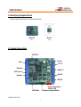
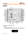
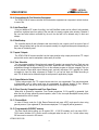
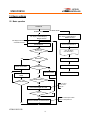
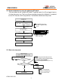
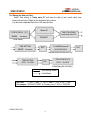
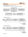
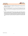
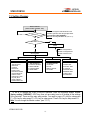
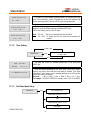
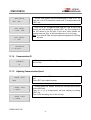
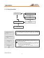
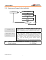
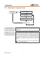
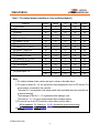
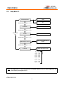
ID TECK
ACCESS CONTROLLER
STAR ICON100
USER’S MANUAL
STAR ICON100
Access Controller
ID TECK Co. Ltd.
ICON100-20011128
1
ID TECK
ACCESS CONTROLLER
STAR ICON100
Table of Contents
1. Important Safety Instructions
3
2. General
3
3. Features
4
4. Specification
4
5. Identifying Supplied Parts
5
6. System Description
5
7. Connection
6
8. System Application
8
9. Wiring for Network
10
10. Functions
10
11. Operation
12
12. Basic settings
13
13. Setting Changes
18
14. Operating status indications
41
15. Warranty and Service
42
ICON100-20011128
2
ID TECK
ACCESS CONTROLLER
STAR ICON100
1. Important Safety Instructions
When using your STAR ICON100, basic safety precautions should always be followed to reduce the
risk of fire, electrical shock, and injury to persons. In addition, the following safety guides should also be
followed:
1. Fully read and understand all instructions and follow them completely.
2. Follow all warnings and instructions marked on the product.
3. Do not use liquid or aerosol cleaners. Use a damp cloth for cleaning. If necessary, use mild soap.
4. Do not use this product near water.
5. Only operate this product using the type of power source indicated. If you are not sure of the type of
power supplied to your installation site, consult your dealer or local power company.
6. Never insert objects of any kind into the product or through the cabinet slots as they may touch
voltage points and/or short circuit parts possibly resulting in fire or electric shock. Never spill liquid of
any kind on the product.
7. Never disassemble this product by yourself; take the unit to a qualified service center whenever
service or repair is required. Opening or removing the covers may expose you to dangerous voltages
or other risks. Also, incorrect reassembly can cause electric shock when the unit is subsequently used.
8. Unplug this product from the Direct Current (DC) power source and refer to qualified service
personnel under these conditions:
a. When the power supply cord or plug is damaged or frayed.
b. If liquid has been spilled on the product.
c. If the product does not operate normally after following the operating instructions in this manual.
Adjust only those controls that are covered by the operating instructions in this manual. Improper
adjustment of other controls that are not covered by this manual may damage the unit and will
often require extensive work by a qualified technician to restore normal operation.
d. If the product exhibits a distinct change in performance.
2. General
The STAR ICON100 is an intelligent single door access controller with a powerful 8 bit
microprocessor to meet the market requirements for a simple and cost-effective access controller. It
is designed to achieve low cost as well as high security, convenience and reliability. This user friendly
device allows you to register 500 ~ 10,000 ID numbers and it can keep 2,500 ~ 7,250 events.
Number of ID & Event can be exchanged under the ratio of 2 to 1 which means every 500 users can
be convert to 250 events. Independent 4 input ports can be connected with various devices such as
exit button, door contact, PIR sensor, fire sensors. Extra reader port allows for user to add external
RF reader for Anti pass back operation. Star ICON100 can be used as not only a standalone access
controller but also a network system communicating via RS-422 and RS-232 communication port. All
setting values including ID numbers, inputs/outputs, real-time clock and time schedule, all event
transaction reports can be downloaded/uploaded from/to the host computer. The STAR ICON100 will
provide you an accurate access control for single door and 3 LED indicators inform you all system
operating status at real time. The STAR ICON100 access controller will give you field proven
reliability and cost-effective solution wherever access controls and high security are required
ICON100-20011128
3
ID TECK
ACCESS CONTROLLER
STAR ICON100
3. Features
-
Single Door Control Panel
2 Reader ports with 26bit Wiegand format
Data memory programmable
Card holder records -------- 500 to 10,000
Off-line stored events ------ 7,250 to 2,500
Anti-Pass Back Operation
Duress mode Operation
Various Time Schedule Operation
4 independent input ports(Exit button, Door contact, Aux #1, Aux #2)
4 output ports including 2 Form-C Relays
All setting values are user programmable from the keypad or from the application software
Door Lock and Unlock functions
One RS-232 port and one RS-422 communication port for easy interfacing to Host computer
Communication Address selectable up to 32ch
Baud rate selectable at 4800, 9600(default),19200bps
3 LEDs (red, green, and yellow) for system operation status
Door open by compulsion and Door open alarm
4. Specification
CPU
Memory
Power
Card Holders/Event buffers
Reader ports/Data format
Input/Output
Communication
LED
Operating environment range
Mounting
Weight
Dimensions
Self diagnostic
Reset
Optional:
Keypad
LCD
: 8bit Microprocessor
: Program memory(64KB ROM)
Data memory(128KB RAM : battery backup)
: DC 12V/ 150mA (max.)
: Memory programmable for:
Card holder records -------- 500 to 10,000
Off-line stored events ------ 7,250 to 2,500
: 2 Reader port / 26bit wiegand format
: 4 Inputs(Exit button, Door contact, Aux #1, Aux #2),
max. rating at DC12V/20mA
: 2 Relay outputs : DC12V~24V/2A max.
: 2 TTL outputs : DC5V/20mA
: One RS-232 port and one RS-422 port
4800, 9600(default), 19200 bps Baud Rate .
: 3 LEDs (red, green, and yellow)
: -35°C to +65°C, 10% to 90% Humidity
: 4 screw mount
: 170g
: 137mm(5.4 ”) x137mm(5.4 ”)
: Yes
: Power on reset & watch dog timer
: 16 Numeric Keypad
: 1x LCD module, 2Lines x 16ch, 65.6 x 13,8mm view area
ICON100-20011128
4
ID TECK
ACCESS CONTROLLER
STAR ICON100
5. Identifying Supplied Parts
Please unpack and check the contents of the box.
Main Unit
(1)
Manual
(1)
6. System Description
DIP S/W
Power
Input
TTL1,2
Reader2
Relay1,2
LED Control
RS-232
Reader1
RS-422
System Operation
Status LED
16 Numeric Keypad Wafer
LCD Wafer
ICON100-20011128
5
ID TECK
ACCESS CONTROLLER
STAR ICON100
7. Connection
Setting address by the addressing DIP switch
1. Initial status
Initial status of the DIP switch is as follows.
The address set by the DIP switch is to be used when operating with application program, so it
must be set equal to application's value. If necessary, see the application program manual.
On
Off
1
2
3
4
ICON100-20011128
6
5
6
7
8
ID TECK
ACCESS CONTROLLER
STAR ICON100
2. Addressing the unit
Table 1 : The relation between Setting and Dip switch
00
01
02
03
04
05
06
07
08
09
10
11
12
13
14
15
1
On
Off
On
Off
On
Off
On
Off
On
Off
On
Off
On
Off
On
Off
2
On
On
Off
Off
On
On
Off
Off
On
On
Off
Off
On
On
Off
Off
3
On
On
On
On
Off
Off
Off
Off
On
On
On
On
Off
Off
Off
Off
4
On
On
On
On
On
On
On
On
Off
Off
Off
Off
Off
Off
Off
Off
5
On
On
On
On
On
On
On
On
On
On
On
On
On
On
On
On
6
On
On
On
On
On
On
On
On
On
On
On
On
On
On
On
On
7
On
On
On
On
On
On
On
On
On
On
On
On
On
On
On
On
8
On
On
On
On
On
On
On
On
On
On
On
On
On
On
On
On
16
17
18
19
20
21
22
23
24
25
26
27
28
29
30
31
1
On
Off
On
Off
On
Off
On
Off
On
Off
On
Off
On
Off
On
Off
2
On
On
Off
Off
On
On
Off
Off
On
On
Off
Off
On
On
Off
Off
3
On
On
On
On
Off
Off
Off
Off
On
On
On
On
Off
Off
Off
Off
4
On
On
On
On
On
On
On
On
Off
Off
Off
Off
Off
Off
Off
Off
5
Off
Off
Off
Off
Off
Off
Off
Off
Off
Off
Off
Off
Off
Off
Off
Off
6
On
On
On
On
On
On
On
On
On
On
On
On
On
On
On
On
7
On
On
On
On
On
On
On
On
On
On
On
On
On
On
On
On
8
On
On
On
On
On
On
On
On
On
On
On
On
On
On
On
On
3. Initializing the unit.
Toggle the switch 8 to 'off' and toggle it back to 'on' when the power is on. Then you will see a
message showing the initialization is completed on the LCD. Press the <ESC> key and finish.
On
Off
1
2
3
ICON100-20011128
7
4
5
6
7
8
ID TECK
ACCESS CONTROLLER
STAR ICON100
8. System Application
Door
Contact
EXIT
Button
GND Input 2
Relay1
Input 1
GND
D1
D0
+12V
GND
Relay2
GND
Reader2
GND
D1
D0
+12V
GND
Input 3
GND
+12V
DC12V
POWER
SUPPLY
Reader1
Door Lock
PIR Sensor
8-1. Power Connection
- Connect (+) wire of DC 12V power to +12V(power port 1) port
- Connect Power GND (-) wire of DC 12V to GND(power port 2) port
Siren
8-2. Door Lock Connection(Relay1)
8-2-1 Connection of POWER FAIL SAFE: Door Lock
- Connect Door RELAY (COM port) to DC +12V (be sure that the existing power supply has
enough capacity to support this accessory or upgrade to a sufficient one.)
- Connect (+) wire of Door Lock to Door RELAY (NO port) port.
- Connect (-) wire of Door Lock to Power GND (-) port.
8-2-2 Connection of POWER FAIL SECURE: Door Lock
- Connect Door RELAY (COM port) to DC +12V (be sure that the existing power supply has
enough capacity to support this accessory or upgrade to a sufficient one.)
- Connect (+) wire of Door Lock to Door RELAY (NC port).
- Connect (-) wire of Door Lock to Power GND(-).
8-3. Alarm Device Connection(Relay2)
- Connect Alarm RELAY (COM port) to DC +12V (be sure that the existing power supply has
enough capacity to support this accessory or upgrade to a sufficient one.)
ICON100-20011128
8
ID TECK
ACCESS CONTROLLER
STAR ICON100
- Connect (+) wire of Alarm Device to Alarm RELAY (NO port) wire.
- Connect (-) wire of Alarm Device to Power GND (-) wire.
8-4. Exit Button Connection
- Connect one of the wires of Exit Button to Exit Button Input.
- Connect the other wire of Exit Button to Power GND(-).
8-5. Door Contact Sensor Connection
- Connect Door Contact sensor(COM) wire to Door Contact Input.
- Connect Door Contact sensor(NO) wire to Power GND(-).
8-6. Auxiliary Input Device Connection (Applied to Input 1,2)
- Connect one wire of the Auxiliary Input Device to the Input(Input 1,2).
- Connect the other wire of Auxiliary Input Device to Power GND(-).
8-7. Wiegand Input Connection From Wiegand Reader(1, 2)
- Connect (+) wire of Reader(1,2) to +12V port of Main Unit.
- Connect (-) wire of Reader(1,2) to GND (-) port of Main Unit.
- Connect Wiegand output DATA0 wire of the additional Reader(1,2) to DATA0(Reader1,2).
- Connect Wiegand output DATA1 wire of the additional Reader(1,2) to DATA1(Reader1,2).
- When installing readers, reader1 set for entry and reader2 set for exit.
* Qualified card readers: 26bit wiegand format reader
EXAMPLE: ID_TECK
: RF series, RFK 101
MOTOROLA
: ARK501+
BALOGH
: Hyper_X
8-8. RS-232 Communication Port Connection
9-pin connector (COM Port, female) is required to connect serial communication RS-232
between Main Unit and Personal Computer.
- Connect RS-232-TX of main unit to pin number 2 of 9-pin connector.
- Connect RS-232-RX of main unit to pin number 3 of 9-pin connector.
- Connect RS-232-GND of Main Unit to pin number 5 of 9-pin connector.
- Plug in 9-pin connector to COM1 or COM2 Port of Personal Computer.
- Install and run Application Software.
8-9. RS-422 Communication Port Connection
RS-422/RS-232 converter is required to connect serial communication RS-422 between Main
Unit and Personal Computer.
- Plug in RS-232 9-pin connector of RS-422/RS-232 converter to COM1 or COM2 Port of
Personal Computer.
- Connect RS-422-TX(-) of Main Unit to RX(-) port of converter.
- Connect RS-422-TX(+) of Main Unit to RX(+) port of converter.
- Connect RS-422-RX(-) of Main Unit to TX(-) port of converter.
- Connect RS-422-RX(+) of Main Unit to TX(+) port of converter.
- Install and run Application Software.
ICON100-20011128
9
ID TECK
ACCESS CONTROLLER
STAR ICON100
9. Wiring for Network
10. Functions
10-1. Standalone Operation
The STAR ICON100 is capable of having two readers (entry and exit). The unit receives card data
signals from the RF readers and determines whether or not to unlock the door. When an input signal is
sent, for example from an activated sensor or if the exit button pressed, the controller generates and
logs an appropriate response. All events are kept in its own memory and sent to the host computer.
The access controller is a true standalone device that in the event of a malfunction, will not affect other
units, even if used in conjunction with one another.
10-2. Operation with Host Computer
All event data can be managed via the host computer. The data transmitted from the controller can be
displayed and stored on the host PC.
10-3. Keypad
In the event that a host PC is not used, the integrated keypad and LCD can also be used for the entire
programming process.
ICON100-20011128
10
ID TECK
ACCESS CONTROLLER
STAR ICON100
10-4. Cooperation with Fire Detection Equipment
The STAR ICON100 access controller and fire detection equipment can cooperate to unlock the door
in case of fire.
10-5. Anti-Pass-Back
Using an additional RF reader for exiting, the Anti-Pass-Back mode can be utilized. Anti-pass-back
prevents a registered user from exiting if the user did not properly register when entering. Likewise if
the user has exited without verification by the unit, the user will not be allowed entry on their next
attempt.
10-6. Data Backup
The controller retains all user information and event data for over a week, even if the event of loss of
power. Using a battery back up the unit can operate normally for a significant time period, depending on
the power of the battery used.
10-7. Inputs/ Outputs
The STAR ICON100 access controller has four input ports(two relay output ports and two TTL output
ports) which can be used to manipulate a wide variety of controls.
10-8. Time Schedule
You can program periods of time when each person(ID number) can access the door. Each user can
be programmed individually to address work shifts, weekends and holidays. All scheduling can be
programmed through the keypad and LCD or via the software program on the host computer. Also you
can set periods of time about output following input, and only output(see 13.2.3 page29), the former
correspond to Input, the latter correspond to Output. So, you can set Input and Output according to
each T/S. All these can be defined through the setup menu or application program.
10-9. Output Behavior Setup
The two relays outputs, two TTL outputs, buzzer sound, etc. are customizable. They may be activated
or deactivated, and in active mode may be programmed for different lengths of time, different
responses to inputs, and can be set through the setup menu or the application program.
10-10. Door Open by Compulsion and Door Open Alarm
When door is opened by compulsion, Door Contact output(see 13.2.3 page29) is generated. And,
when the door is being opened by normal operation, after 20 sec. door-open alarm(blink buzzer) will be
generated until the door is closed.
10-11. Duress Mode
In case of Duress, enter the 2 digit Duress Password and press <ENT> and open the door using
general process. If you registered ID, then duress output(see 13.2.3 page29) will be generated.
10-12. Programmable ID/EVENT memory
This user friendly device allows you to register 500 ~ 10,000 ID numbers and it can keep 2,500 ~
7,250 events. Number of ID & Event can be exchanged under the ratio of 2 to 1 which means every
500 users can be convert to 250 events.
ICON100-20011128
11
ID TECK
ACCESS CONTROLLER
STAR ICON100
11. Operation
11-1. Normal Operation Mode (Safe Mode)
When the Main Unit operates in standby mode(waiting for RF card), the red LED is lit.
11-2. Open the Door
When a registered card(or PIN) is read, the Door will open for 3 seconds.(default)
.
Reader
Registered Card
11-3. Exit (Open the Door)
To request for exit from the inside, an Exit Button(or Exit Reader) can be used to open the door.
Reader
Registered Card
11-4. Action And Alarm Caused by Unregistered Card
When an unregistered card is read the access is denied and the alarm can be activated for 3
seconds along with a buzzer sound.
Reader
Unregistered Card
(If you do not want to activate the Alarm in case of unregistered access attempt, then you can
change this setting as shown in section 13.2.3.)
ICON100-20011128
12
ID TECK
ACCESS CONTROLLER
STAR ICON100
12. Basic settings
12.1 Basic operation
POWER ON
H/W RESET MODE
GENERAL BOOT
INITIAL BEEP
LCD display : STAR ION100[F1]
MM/DD hh/mm/ss
INITIAL BEEP
LCD display : STAR ION100[F1]
MM/DD hh/mm/ss
LCD display model name,
current date and time
NO
SYSTEM READY
Turn OFF DIP Switch No. 8
ID INPUT ?
(Card or Key)
"Turn ON DIP.8"
"Turn OFF Power..."
YES
YES
MASTER ID ?
Turn ON DIP Switch No. 8
NO
ENTER SETUP MENU
NO
SETTING IN SETUP
MODE
Turn off Power
DURESS P/W ?
NO
YES
DURESS FLAG SET
System initialization completion
REGISTERED ID ?
END SETTING ?
P/W, T/S, Door,
Duress mode,
APB, etc...
YES
CHECK REGISTERED ID FLAGS
NO
NO
RIGHT ?
YES
OUTPUT CONTROL OF EACH STATUS
YES
ICON100-20011128
13
You can select output of each
status in setup menu F2
ID TECK
ACCESS CONTROLLER
STAR ICON100
12.2 System initialization by using the addressing DIP switch
You can initialize the unit, using the DIP switch. Toggle the switch 8 to 'off' and toggle it back to
'on' when the power is on. Then you will see a message showing the initialization is completed
on the LCD. Press the <ESC> key and finish. The illustration below shows the process.
POWER ON
INITIAL BEEP
LCD display : STAR ICON100 [F1]
MM/DD hh/mm/ss
You can initialize the unit, using
the DIP switch. Toggle the switch
No. 8 to 'off'
"Turn ON DIP.8"
"Turn OFF Power..."
On
Off
Turn ON DIP Switch No. 8
1
2
3
4
5
6
7
8
Figure1. DIP switch
Turn off Power
System initialization completion
12.3 Enter into setup menu
INITIAL DISPLAY
(MODEL NAME, CURRENT TIME)
NO
To set or to change the STAR ICON100 access
controller's operation, enter the eight-digit Master
number(factory setting '00000000' ).
Note You can change the Master ID. (see 13.1.7)
ID INPUT ?
YES
MASTER ID ?
NO
OPERATE GENERAL
MODE
YES
Operation of Registered ID
Operation of Unregistered ID
Operation of Duress mode
SETUP MODE
ICON100-20011128
14
ID TECK
ACCESS CONTROLLER
STAR ICON100
12.4 Setting the Date and Time
Select ‘Time setting’ in “Setup menu F1” and enter the data of year /month /date /hour
/minute /second /day (15digit) as the illustration below shows.
You will see the adjusted time on the LCD when finished.
Master ID
Select ‘Time Setting’
menu(Setup menu F1)
STAR ICON100 [F1]
MM/DD
hh:mm:ss
Initial display
TIME SETTING
MM/DD hh:mm:ss
“00000000”
YYYYMMDDhhmmssW
200107050918305
ENT
“Year/Month/Day/Hour/Min./Sec./Day”
TIME SETTING
07/05 09:18:30
ESC
STAR ICON100 [F1]
07/05 09:18:30
Initial display after time setting
: After change Master
: Initial Master
Day code
1 : Sun., 2 : Mon., 3 : Tue., 4 : Wed., 5 : Thu., 6 : Fri., 7 : Sat.
For example : '200106071330253' for Tuesday, June 7, 2001 01:30:25PM.
ICON100-20011128
15
ENT
ID TECK
ACCESS CONTROLLER
STAR ICON100
12.5 Registering Cards
You can register Cards(or PIN) to the system. (See, 13.3.1)
Select ‘ID REGISTRATION’ in Setup menu 3, follow through illustration below shows.
Master ID
Select ID Registration
menu (Setup menu F3)
STAR ICON100 [F1]
MM/DD
hh:mm:ss
“00000000”
Initial display
ID REGISTRATION
ID REGISTRATION
1-Card, 2-Key
ENT
1. Registration by RF Cards
“1”Key
Scanning…
Approach card
reader1
25500100
PW1234 TS00 RD3
Input PW/TS/RD + <ENT>
Success
Completio
2. Registration by Key_pad
“2”key
ID [________]
PW____ TS__ RD_
Input
Registration
key (8digit+<ENT>)
00000100
PW1234 TS00 RD3
Input PW/TS/RD + <ENT>
Success
ICON100-20011128
16
Completion
ID TECK
ACCESS CONTROLLER
STAR ICON100
When registering cards,
1. The 'PW' is for password input. The password is needed to access doors when the controller is
operating in RF + PW mode. But regardless of the operating mode, it is necessary to input a
password when registering.
2. The 'TS' is for Time Schedule index(01~10). To control the accessible periods of time for each
card, set Time schedules first(see 13.2.1 page27) and enter the Time Schedule index number
here.
If there is no need to apply the Time Schedule(anytime accessible with that card), enter '00' for
the value.
3. The 'RD' is for selecting accessible reader for the card. Usually ‘3’ (both readers) is used when
using both entry and exit readers. If '1' is entered for the value, only reader 1 will recognize the
card and reader 2 will deny access, indicating 'ACCESS DOOR ERR' on the LCD (this is also
the choice when using a one reader setup, meaning using one reader for entry and no reader
for exit). Likewise, when '2' is entered, only the reader 2 is accessible with that card and reader
1 access will be denied. And again, both readers are accessible when '3' is entered for the 'RD'
value.
ICON100-20011128
17
ID TECK
ACCESS CONTROLLER
STAR ICON100
13. Setting Changes
INITIAL DISPLAY
(MODEL NAME, CURRENT TIME)
NO
To set or to change the STAR ICON100 access
controller's operation, enter the eight-digit Master
number(factory setting '00000000' ).
Note You can change the Master ID. (see 13.1.7)
ID INPUT ?
YES
MASTER ID ?
NO
OPERATE GENERAL
MODE
YES
Operation of Registered ID
Operation of Unregistered ID
Operation of Duress mode
SETUP MODE
SETUP F1 MODE
1. MODE SELECTION
2. TIME SETTTING
3. APB SETUP
4. COMM ID
5. BAUD RATE
6. EVENT CLEAR
7. MASTER ID CHANGE
8. SYSTEM INITIALIZE
9. CARD ID CLEAR
10. TIME SCHE CLEAR
11. RF_PIN_INPUT
12. EVENT MEMORY
13. DURESS MODE SET
SETUP F2 MODE
1. TIME SCHEDULE
2. HOLIDAY SETTING
3. IN/OUT DEFINE
4. HOLIDAY INDEX
5. MODE INDEX
SETUP F3 MODE
1. ID REGISTRATION
2. ID DELETE
3. ID LIST
4. REG. ID COUNT
5. ID COUNT
SETUP F4 MODE
1. VERSION
2. SRAM TEST
3. OUTPUT TEST
4. LCD TEST
5. KEYPAD TEST
6. READER TEST
7. INPUT TEST
8. COMM TEST
To set or to change the STAR ICON100’s operation, enter the eight-digit Master number
(factory setting “00000000”) <ENT>key, then you are ready to set or to change all the settings
of the controller. There are four main setup menus. You need to press <F1> key for setup menu
F1, <F2> key for setup menu F2, <F3> key for setup menu F3 and <F4> key for setup menu F4.
Note You can change the Master number. (see 13.1.7)
ICON100-20011128
18
ID TECK
ACCESS CONTROLLER
STAR ICON100
13.1
Setup Menu F1
MODE SELECTION
RF Only (DEFAULT)
SEARCHING KEY(key<4> or <6>)
TIME SETTING
RF+P/W( PassWord )
15 digit key in
SEARCHING KEY(key<4> or <6>)
NOT USE (DEFAULT)
APB SETUP
USE
SEARCHING KEY(key<4> or <6>)
ALL CLEAR
COMM ID
SEARCHING KEY
SEARCHING KEY(key<4> or <6>)
BAUD RATE
4800
9600 (DEFAULT)
SEARCHING KEY(key<4> or <6>)
19200
38400
EVENT CLEAR
YES
SEARCHING KEY(key<4> or <6>)
MASTER ID CHANGE
NO
KEY
SEARCHING KEY(key<4> or <6>)
Note There are four main setup menus. You need to press <F1> key for setup menu F1, <F2>
key for setup menu F2, <F3> key for setup menu F3 and <F4> key for setup menu F4. The
keys <4>, <6>, <2> and <8> are used to change submenus or to select values, <ENT> to
select and set, <ESC> to go to upper step or to leave setup mode. When selecting mode or
setting values is completed, in all kind of menu, the figure on the LCD returns to the first figure
of that menu. Then, for the next setting, use <4> and <6> keys(searching key).
ICON100-20011128
19
ID TECK
ACCESS CONTROLLER
STAR ICON100
SEARCHING KEY(key<4> or <6>)
SYSTEM INITIALIZE
YES
SEARCHING KEY(key<4> or <6>)
NO
YES
CARD ID CLEAR
SEARCHING KEY(key<4> or <6>)
TIME SCHE CLEAR
NO
YES
SEARCHING KEY
SEARCHING KEY(key<4> or <6>)
RF_PIN_INPUT
NO
ENABLE
SEARCHING KEY(key<4> or <6>)
EVENT MEMORY
DISABLE (DEFAULT)
NOT USE
SEARCHING KEY(key<4> or <6>)
DURESS MODE SET
USE (DEFAULT)
NOT USE (DEFAULT)
USE
DURESS P/W SETTING
13.1.1
Changing Operating Mode
MODE SELECTION
'ENT'
RF Only (DEFAULT)
SEARCHING KEY(key<4> or <6>)
RF+P/W( PassWord 4 digit )
ICON100-20011128
20
ID TECK
ACCESS CONTROLLER
STAR ICON100
This menu is to select reader1 operating mode. You may choose to use
prox, PIN # verification, or both. The lower line on the LCD indicates the
current operating mode. Press the <ENT> key to change the mode.
MODE SELECTION
RF ONLY
Then, this figure appears on the LCD, press <4> key or <6> key to
toggle the mode, and finish selecting by pressing <ENT> key.
For the next setting, use <4> and <6> keys.
MODE SELECTION
--> RF ONLY
Note: RF only : The door is accessible with the card alone.
RF + PW : To access the door, the card and the password is
needed.
MODE SELECTION
--> RF + PW
13.1.2
Time Setting
15 digit + 'ENT'
ENTER : YYYYMMDDhhmmssW
(15 digit) + 'ENT'
'ENT'
TIME SETTING
'ESC'
TIME SETTING
MM/DD
hh:mm:ss
YYYYMMDDhhmmssW
______________
13.1.3
The lower line on the LCD indicates present time. To set time, press
<ENT> key.
Enter the correct information of the year, month, date, hour, minute,
second, day code in due order, then the setting is finished. If the input
information is out of range, an error message appears on the LCD and the
current time value is to be kept.
Day code 1 : Sun., 2 : Mon., 3 : Tue., 4 : Wed., 5 : Thu., 6 : Fri., 7 : Sat.
For example : '200106071330253' for Tuesday, June 7, 2001 01:30:25PM.
Anti-Pass-Back Setup
APB SETUP
'ENT'
NOT USE(DEFAULT)
SEARCHING KEY(key<4> or <6>)
USE
SEARCHING KEY(key<4> or <6>)
ALL CLEAR
ICON100-20011128
21
ID TECK
ACCESS CONTROLLER
STAR ICON100
APB
NOT
SETUP
USE
APB
SETUP
--> NOT USE
APB
SETUP
You can select whether the Anti-Pass-Back(APB) is used or not. The
lower line on the LCD indicates the current mode. To change mode, press
<ENT> key.
Press <4> or <6> to toggle the mode, from NOT USE to USE or the
reverse, and finish selecting by pressing <ENT> key. Then the figure on
the LCD returns to the first figure of that menu, which indicates the
selected mode now. Then, for the next setting, use <4> and <6> keys.
Note: If you select All Clear, then system ignore all registered ID’s APB flag
only once.
--> USE
APB SETUP
--> All Clear
13.1.4
Communication ID
COMM ID
00
13.1.5
This is communication ID checking menu. For the next setting, use <4>
and <6> keys.
Adjusting Communication Speed
BAUD
RATE
9600
BAUD
RATE
--> 9600
BAUD
The number on the LCD is the current communication speed in Baud
rate.
Press <ENT> key to adjust the speed.
Available speeds are 4800bps, 9600bps and 19200bps and the default
value is 9600 baud.
Press <4> or <6> to change speed, and finish selecting by pressing
<ENT> key.
Then, for the next setting, use <4> and <6> keys.
RATE
-->19200
ICON100-20011128
22
ID TECK
ACCESS CONTROLLER
STAR ICON100
13.1.6
Clearing Event Data Buffer
EVENT
Event
1 - Yes ,
13.1.7
CLEAR
Used to erase ALL of the event data such as the permitted access and
denied access records. If you want to do so, press <ENT> key.
Clear
When this figure appears on the LCD, press <1> key to clear and <0>
key to cancel the operation.
CAUTION: Be careful in using this operation, or you may lose
important data.
0 - No
Changing Master Number
MASTER ID CHANGE
Press <ENT> key to change the current Master ID. You should use the
new Master ID to access the setup menu since the change is finished.
MASTER ID CHANGE
You should use eight digit number. Enter the eight-digit new Master
number.
And press <ENT> key.
[_ _ _ _ _ _ _ _]
Master
Card
Registered
13.1.8
The figure indicates that changing Master ID is finished successfully,
and soon, will return to the first figure of this menu. For the next setting,
use <4> and <6> keys.
Initializing the System
SYS INITIALIZE
Sys Initializing
1 - Yes ,
0 - No
System
Initializing..
This operation will initialize the STAR ICON100. Press <ENT> key, if an
initialization is needed (first time installation or resetting in the event of a
malfunction). CAUTION: Initializing will erase all stored data incl.
registered IDs event data.
When this figure appears on the LCD, press <1> key to clear and <0>
key to cancel the operation, then the LCD displays the first figure of this
menu.
This message appears while the system is being initialized. When
finished, you will be automatically returned to the setup menu.
ICON100-20011128
23
ID TECK
ACCESS CONTROLLER
STAR ICON100
13.1.9
Clearing Card IDs
CARD ID CLEAR
Card ID Clear
1 - Yes ,
13.1.10
0 - No
When this figure appears on the LCD, press <1> key to clear and <0>
key to cancel the operation, then the LCD automatically returns to the start
menu.
CAUTION: Be careful in using this operation, or you may lose
important data.
Clearing Time Schedule
TIME SCHE CLEAR
Time Sche
1 - Yes ,
13.1.11
Used to erase ALL the card ID data. stored in the device.
If you want to do so, press <ENT> key.
Clear
0 - No
Used to erase ALL the time schedules. If you want to do so, press
<ENT> key. CAUTION: This function will erase ALL programmed time
schedules.
When this figure appears on the LCD, press <1> key to clear and <0>
key to cancel the operation, then the LCD automatically returns to the start
menu.
Selecting ID Input mode
RF_PIN_INPUT
ENABLE
You can enable PIN(card number) to be input through the keypad, so
that someone who doesn't carry RF cards with him can access the door.
When it is disabled, accessing the door by keypad will be denied.
The display shows the current mode. Press <ENT> key to toggle the
mode.
RF_PIN_INPUT
-->DISABLE
13.1.12
Selecting Event memory USE or NOT USE
EVENT MEMORY
NOT USE
EVENT MEMORY
You can select whether the Stand Alone is used or not. The lower line
on the LCD indicates the current mode. Press <4> or <6> to toggle the
mode, from NOT USE to USE or the reverse, and finish selecting by
pressing <ENT> key.
Note: If you select NOT USE, then system will not display event full
message.
-->USE
ICON100-20011128
24
ID TECK
ACCESS CONTROLLER
STAR ICON100
13.1.13 Setting Duress Mode
DURESS MODE SET
'ENT'
NOT USE(DEFAULT)
SELECT KEY(4 or 6 keys)
USE
'ESC'
IF DURESS MODE USED
DISPLAY CURRENT P/W
DURESS P/W
'ENT'
ENTER NEW P/W
( 2 digit + 'ENT')
DURESS MODE SET
NOT USE
You can select whether the Duress mode is used or not. The lower line
on the LCD indicates the current mode. To change mode, press <ENT>
key.
DURESS MODE SET
--> USE
DURESS P/W
00
DURESS P/W
00
If you select USE, then system displays the current DURESS P/W. To
change P/W, press <ENT> key.
Note: You can set the duress output in setup menu F2 ( in/out define ). In
case of Duress, enter the 2 digit Duress Password and press <ENT>
and open the door using general process.
If you registered ID, then duress output(see 13.2.3) will be
generated.
ICON100-20011128
25
ID TECK
ACCESS CONTROLLER
STAR ICON100
13.2
Setup Menu F2
INDEX : 01 ~ 10
WEEKLY: HOL, SUN, MON,... SAT
NO. : 01 ~ 05
TIME SCHEDULE
SEARCHING KEY(key<4> or <6>)
INDEX : 01 ~ 10
NO. : 01 ~ 32
HOLIDAY DEFINE
01: EXIT
02: DOOR CONTACT
03: INPUT 1
04: INPUT 2
05: TAMPER S/W
06: R1 ID OK
07: R1 ID ERROR
08: R1 T/S ERROR
09: R1 APB ERROR
10: R2 ID OK
11: R2 ID ERROR
12: R2 T/S ERROR
13: R2 APB ERROR
14: DURESS MODE
15: OUTPUT T/S
16: IN/OUT T/S
SEARCHING KEY(key<4> or <6>)
SEARCHING
KEY
IN/OUT DEFINE
SEARCHING KEY(key<4> or <6>)
HOLIDAY INDEX
HOLIDAY DEFINE INDEX : 01 ~ 10
SEARCHING KEY(key<4> or <6>)
MODE INDEX
TIME SCHEDULE INDEX : 01 ~ 10
Note The keys <4>, <6>, <2> and <8> are used to change menu, <ENT> to select and
store. Press <ESC> to go to back one level and/or to leave setup mode.
ICON100-20011128
26
ID TECK
ACCESS CONTROLLER
STAR ICON100
13.2.1
Registering and Changing Time Schedule
TIME SCHEDULE
'ENT'
DISPLAY CURRENT T/S
SELECT T/S NUMBER AND INDEX
(USE '2','8','4','6' KEY)
'ENT'
ENTER T/S(8 DIGIT)
(START TIME(hh:mm)-END TIME(hh:mm))
YES or Error
NO
or ESC
TIME SCHEDULE
T/S : 01 HOL : 1
00:00 - 00:00
NEXT?
You may program time schedules to grant and restrict access for each
user. There can be up to ten different schedules. A minimum of one
schedule must be defined. If only one schedule is programmed the most
common setting allows access for all users 24 hours / day. A time schedule
can be programmed for each day of the week and holidays (see 13.2.2
page 28), and five shifts can be defined for each day. To set time
schedules, press <ENT> key from this menu.
If you want to set time schedules, press <ENT> key when this figure is
displayed.
Press <2> key or <8> key to adjust the Time Schedule (T/S) number (110) and the day of the week (Mon-Sun and ‘HOL’). Define which shift of the
day (1-5), using the <4> key and <6> key. ‘HOL’ refers to specific holidays
you will register(see 13.2.2 page 28). Press <ENT> key, and the cursor will
blink, then enter the beginning time of the period, in the form of hour(2digit):minute(2-digit) and the ending time in the same form. Then the lower
line will indicate the defined period. For more schedules, repeat the
process.
To end time scheduling, press <ESC> key.
☞. Possible values for time scheduling
1) Time schedule number : 01 ~ 10 (Needed when IDs are registered)
2) A day of the week
: MON, TUE, WED, THU, FRI, SAT, SUN, HOL
: 1 ~ 5(referred to the five periods of time of a day)
3) Index
ICON100-20011128
27
ID TECK
ACCESS CONTROLLER
STAR ICON100
13.2.2
Registering and Changing Holiday Time Schedule
HOLIDAY T/S
'ENT'
DISPLAY CURRENT T/S
SELECT T/S NUMBER AND INDEX
(USE '2','8','4','6' KEY)
'ENT'
ENTER T/S(4 DIGIT)
(MM:DD)
NO
or ESC
HOLIDAY T/S
HOL
T/S: 01
00 : 00
☞.
#01
NEXT?
YES or Error
You can register up to 32 specified “holidays,” per year for each
schedule setting. There can be 10 other registration sets created, meaning
holidays can be set for up to 10 years. Press <ENT> to register the days.
With <2> key and <8> key, select the date registration set number
(1~10), and with <4> key and <6> key, select the index for the days (1~32).
Then, press <ENT> key, and the cursor will blink, then enter the date, in
the form of Month (1~12):date, Then the LCD will indicate the defined date.
Now, a day has been registered. For further registration, repeat the
process.
To end registering the days, press <ESC> key to return to the setup menu.
1) Holiday Time schedule(Date registration set) number : 01 ~ 10(10 years)
2) Index for the days
: 01 ~ 32(32 days)
ICON100-20011128
28
ID TECK
ACCESS CONTROLLER
STAR ICON100
13.2.3
Defining Outputs in Compliance with Inputs
IN/OUT DEFINE
'ENT'
DISPLAY CURRENT SET
SELECT INDEX
(USE '4','6' KEY)
'ENT'
ENTER NEW TIME OR T/S INDEX
(10 DIGIT OR EVEN DIGIT) + 'ENT'
NO
or ESC
IN/OUT DEFINE
1. EXIT
03
00 00 00 00
NEXT?
YES or Error
You can program or deactivate each output to be generated and choose
how long (in seconds) they will last. There are default values as seen in the
table 2 below.
Select input sources by changing index No. with the keys <4> or <6>,
and press <ENT> key, and you’ll see a cursor blinking at the first digit, from
the left, of the five couples of digit, which corresponds to relay1, relay2,
TTL1, TTL2 and buzzer, respectively. Then enter the delay times(refer to
the table below) one by one. Now, an inputs/outputs definition has
completed. For further definition, repeat the process. To end defining
inputs/outputs, press <ESC> key, and you will see the first figure of the
menu.
Note: The five couples of digit of [15] Output T/S and [16] Input/Output T/S
are time schedule indexes.
ICON100-20011128
29
ID TECK
ACCESS CONTROLLER
STAR ICON100
Table 2 : The relation between index(Source, Input and Output(default) )
Index No
[1] Exit button
[2] Door contact
[3] Input #1
[4] Input #2
[5] Tamper S/W
[6] Reader(1) ID OK
[7] Reader(1) ID Error
[8] Reader(1) ID T/S Error
[9] Reader(1) APB Error
[10] Reader(2) ID OK
[11] Reader(2) ID Error
[12] Reader(2) ID T/S Error
[13] Reader(2) APB Error
[14] Duress Mode
[15] Output T/S
[16] Input/Output T/S
Relay1
03
00
00
00
00
03
00
00
00
03
00
00
00
03
00
Input1
00
Relay2
00
00
00
00
00
00
03
03
03
00
03
03
03
00
00
Input2
00
TTL1
00
00
00
00
00
00
00
00
00
00
00
00
00
03
00
Input3
00
TTL2
00
00
00
00
00
00
00
00
00
00
00
00
00
03
00
Input4
00
Buzzer
00
00
00
00
00
00
00
00
00
00
00
00
00
03
00
Input5
00
Note ;
1) The relation between index number and input is shown in the table above.
2) The inputs of index No. 3~4 are signals from extra equipments, such as PIR sensor, Fire
sensor and etc, connected to the controller.
The index No. 5 corresponds to the tamper switch input (activated when the controller has
a physical damage).
The messages of the No. 6 ~ 13 is generated after reading a card.
The index No. 15 ~ 16 are not output time but time schedule number.
3) The second line of the LCD shows the output status.( see the table )
( 00 :No operation , 99 : Always on , 01~98 : Activated for given seconds long )
4) Relay 1(Lock Door), Relay 2(Alarm)
ICON100-20011128
30
ID TECK
ACCESS CONTROLLER
STAR ICON100
13.2.4
Setting Holiday Index
HOLIDAY INDEX
00
HOLIDAY INDEX
00
13.2.5
You choose which Holiday time schedule ( date registration set ) is to be
used. The default index is “00”. Choose the schedule you programmed
(01-10). If necessary, press <ENT> key.
Enter Index number(00~10) and press <ESC> key to finish selecting.
You will then automatically be returned to the setup menu.
Setting Mode Index
MODE INDEX
00
MODE INDEX
00
The function to apply the Time schedule to operating mode, which must
be applied. The default index is “00”. If necessary, press <ENT> key.
Enter Index number(00~10) and finish. During the period of time the
applied T/S indicates, your controller will operate in RF only mode and for
the rest of the time, in RF card + four digit password mode. Press <ESC>
key to end the selecting, then the first figure of the menu is displayed on
th LCD
ICON100-20011128
31
ID TECK
ACCESS CONTROLLER
STAR ICON100
13.3
Setup Menu F3
ID REGISTRATION
CARD
KEY
SEARCHING KEY(key<4> or <6>)
ID DELETE
ENTER ID (8 digit key in)
SEARCHING KEY(key<4> or <6>)
SEARCHING
KEY
ID LIST
DISPLAY REGISTERED ID
SEARCHING KEY(key<4> or <6>)
DISPLAY REGISTRATION ID
COUNT
REGISTERED ID COUNT
SEARCHING KEY(key<4> or <6>)
ENTER POSSIBLE
REGISTRATION ID COUNT
ID COUNT
ID / EVENT
500 / 7,250
1,000 / 7,000
1,500 / 6,750
2,000 / 6,500
2,500 / 6,250
3,000 / 6,000
:
/
:
:
/
:
9,000 / 3,000
9,500 / 2,750
10,000 / 2,500
Note: On setup menu F3, there are functions to register additional IDs, to delete registered IDs
and to display the registered IDs.
ICON100-20011128
32
ID TECK
ACCESS CONTROLLER
STAR ICON100
13.3.1
Registering IDs
ID REGISTRATION
'ENT'
REGISTRATION SELECT
CARD or KEY ?
ERROR DISPLAY
Invalid Card ID
Invalid T/S 1
Invalid T/S 2
Invalid RD
CARD
PRESENT CARD
KEY
ENTER NEW ID
(8 digit - Card data)
YES
Card ID Error ?
NO
INPUT
PW, TS, RD
YES
PW, TS, RD Error ?
NO
ID REGISTRATION END
ID REGISTRATION
ID REGISTRATION
1: Card,
2: Key
Scanning …
[_ _ _ _ _ _ _ _]
PW_ _ _ _ TS_ _ RD_
This is ID registration menu. To register additional IDs.
Press <ENT> key.
ID Number is registered in the controller by RF cards or through the
keypad. For RF cards, Press <1>key, the keypad, <2>key, or you can quit
the registration by pressing <ESC>key.
The reader is waiting for an RF card which is to be registered. The card
number will appear with a beep as the card is read.
This figure appears When you press the <2>key for through keypad
registration, then you are to enter eight-digit ID number. The ID number is
card number format.
Eight digit ID : Upper 3 digit : 0 ~ 255
Lower 5 digit : 0 ~ 65535
ICON100-20011128
33
ID TECK
ACCESS CONTROLLER
STAR ICON100
XXXXXXXX
PW_ _ _ _ TS_ _ RD_
ID Registered
13.3.2
The LCD's upper line shows the number read, and the lower line
indicates that the four-digit password, time schedule index and reader code
are needed. Enter those values, referring to the following information. Then
the registration of the card is finished, and the reader will be waiting for
another card, displaying the second menu of the menu. Press <ESC> key
to end registering IDs, then the first figure of the menu will appear.
1) PW(password) : the password used in RF + password mode.
2) TS(Time schedule) :
00
: Anytime accessible
01 ~ 10
: Accessible according to each T/S index
3) RD(Reader code) - 1 : for using reader 1 alone,
2 : for using reader 2 alone,
3 : for using both reader 1 and 2.
Deleting IDs
ID DELETE
'ENT'
ENTER CARD NO. (8 digit)
'ENT'
DISPLAY
REGISTERED ID
DISPLAY
UNREGISTERED ID
ID DELETE
Enter
Card No.
-> _ _ _ _ _ _ _ _
ID Deleted
YES
REGISTERED ID?
NO
To delete some registered ID, press <ENT> key.
Enter the eight-digit ID number that you want to delete. Then the
following message will show on the LCD.
The display shows on the LCD for a second, indicating that the deletion
is finished successfully, and then the first figure of the menu appears.
ICON100-20011128
34
ID TECK
ACCESS CONTROLLER
STAR ICON100
13.3.3
Listing Registered IDs
ID
LIST
If you wish to list the registered user IDs, press the <ENT> key in this
menu.
This message is displayed when there is no registered users.
MEMORY
EMPTY
XXXXXXXX
PWXXXX TSXX RDX
ID LIST TOP
ID LIST BOTTOM
13.3.4
An ID number, the password, the applied T/S and the reader code are
displayed on the LCD, and you can scroll to the next ID using the <4> and
<6> keys. Press <ESC> key when you finished to return to the setup
This message will appear momentarily when scrolling back to the top of
the list (using the <4> key). After a few seconds the ID for the first user
reappears.
This message will appear momentarily when scrolling forward (using the
<6> key). After a few seconds it disappears revealing the very first ID
number.
Counting Registered IDs
REGISTERED ID
This menu displays the total number of registered IDs .
XXXXX
ICON100-20011128
35
ID TECK
ACCESS CONTROLLER
STAR ICON100
13.3.5
Setting Possible Registration ID Count
ID COUNT
'ENT'
EVENT MEMORY
EMPTY ?
YES
ENTER NO. (3 ~ 5 digit)
NO
DISPLAY "EVENT MEMORY"
NOT EMPTY
ID COUNT VALID ?
NO
YES
DISPLAY "INVALID COUNT"
DISPLAY "ID TOTAL COUNT"
" WRONG !!!"
NO
REGISTERED ID COUNT
< ENTER NO. ?
YES
COMPLETE
ID COUNT
500
ENTER ID COUNT
[_ _ _ _ _]
EVENT MEMORY
NOT EMPTY !!!
ID TOTAL COUNT
Wrong !!!
You should choose which possible registration ID count is to be applied.
The default count is “500”( up to 7,250 events can be stored off-line. ).
If necessary, press <ENT> key.
This figure appears When you press the <ENT>key( and event memory
is empty or not used.). You are to enter a new upper limit of ID registration
which must be a multiple of 500.
You'll see this message when the event memory have been used and
it's not empty. You can try again after uploading the data to the host or
deleting them, using the setup mode F1.
This message will show when the entered number is less than the total
number of the registered IDs. If you want to delete some of the IDs and
reduce the possible registration ID count, clear the event memory, using
the setup mode F1 first and try again from the beginning.
ICON100-20011128
36
ID TECK
ACCESS CONTROLLER
STAR ICON100
13.4
Setup Menu F4
DISPLAY CURRENT F/W
VERSION
VERSION
SEARCHING KEY(key<4> or <6>)
SRAM TEST
SRAM TEST
SEARCHING KEY(key<4> or <6>)
OUTPUT TEST
OUTPUT TEST
SEARCHING KEY(key<4> or <6>)
LCD TEST
LCD TEST
SEARCHING SEARCHING KEY(key<4> or <6>)
KEY
KEYPAD TEST
KEYPAD TEST
SEARCHING KEY(key<4> or <6>)
READER TEST
READER TEST
SEARCHING KEY(key<4> or <6>)
INPUT TEST
INPUT TEST
SEARCHING KEY(key<4> or <6>)
COMMUNICATION TEST
(RS-232)
COMM TEST
Note: On setup menu F4, there are self-diagnosis functions to test the performances of the
operations. To test, press <ENT> key.
ICON100-20011128
37
ID TECK
ACCESS CONTROLLER
STAR ICON100
13.4.1
VERSION
The version of the controller’s firmware is displayed on the LCD.
Press <4> or <6> key to look for other menus of setup menu F4.
VERSION
F/W : Rev. 2.5
13.4.2
SRAM TEST
To test the memory, press <ENT> key.
SRAM TEST
This message would indicate the SRAM has problems. In this event,
contact technical support. Press any key to return to the setup menu. Use
<4> key and <6> key for testing other performances.
Memory fail !!! 0
RAM testing...
This message appears when the SRAM is operating normally.
Press any key to return to the setup menu. Use <4> key and <6> key for
testing other performances.
RAM test pass ! ! !
Press
13.4.3
any
key . . .
Outputs TEST
OUTPUT TEST
ENT
RELAY 1 TEST
(ACTIVATED TWO TIMES)
RELAY 2 TEST
(ACTIVATED TWO TIMES)
TTL OUTPUT 1 TEST
(ACTIVATED TWO TIMES)
TTL OUTPUT 2 TEST
(ACTIVATED TWO TIMES)
BUZZER TEST
(ACTIVATED TWO TIMES)
ANY KEY
OUTPUT TEST END
ICON100-20011128
38
This test is applicable to Relay1
and green LED.
This test is applicable to Relay2
and yellow LED.
This test is applicable to TTL1
output.
This test is applicable to TTL2
output.
This test is applicable to Buzzer
output.
ID TECK
ACCESS CONTROLLER
STAR ICON100
OUTPUT TEST
OUTPUT
5
Press any key . . .
13.4.4
LCD
TEST
To test the performance of the LCD, press <ENT> key. As the test
proceeds several characters will move quickly from right to left.
Last
Update
This means the test has finished. Press any key to return to the setup
menu. Use <4> key and <6> key for testing other performances.
Keypad TEST
KEYPAD
TEST
0123456789ABCDEF
13.4.6
This figure means that the test has finished. Press any key to return to
the setup menu. Use <4> or <6> key to scroll to perform other tests.
LCD TEST
Press any key . . .
13.4.5
To test the output performances, press <ENT> key. If the output
performance has no problems, the test will proceed as follows:
First, the green LED blinks twice as the relay is being shorted and
opened twice. The relay makes a clicking sound as it runs. Second, the
yellow LED blinks twice as the relay is being shorted and opened twice.
The relay makes a clicking sound as it works. Third, the LCD changes its
figure, ’ON, OFF, ON, OFF’. Fourth, the buzzer beeps twice.
Note: The LCD provides no message to indicate if the test has finished
successfully
To test the performance of the keypad, press <ENT> key.
When operating normally, pressing the keys on the keypad will display
the corresponding letter on the LCD.
Note: For function keys, the letters A, B, C, D, E and F will refer to the
<F1>,
<F2>, <F3>, <F4>, <ESC> and <ENT>key, respectively.
Readers TEST
READER
TEST
To test the performance of the reader, press <ENT> key.
ICON100-20011128
39
ID TECK
ACCESS CONTROLLER
STAR ICON100
The reader is waiting for an RF card to read. Present an RF card to the
reader.
Scanning . . .
Reader 1
00312345
Reader No.
13.4.7
Card No.
Input and DIP Switch TEST
INPUT
TEST
INPUT
TEST
11111111
To test the performance of input ports , press <ENT> key.
11111
INPUT 1
DIP S/W 1
13.4.8
The test has completed successfully if the LCD displays the ID card
number ( example shown to left ).
The fore part of the lower line on the LCD indicates DIP switch status
and the rear part indicates the status of the five input signals.
Note: 1. DIP switch : “1”=ON, “0”=OFF
2. Input 1~4 : “0”=ON , “1”=OFF
3. Input 5
: “0”=OFF, “1”=ON
Communication TEST
COMM TEST
Connect the RS-232 Rx, Tx wires
'ENT'
PASSED ?
NO
YES
DISPLAY TEST PASS
ANY KEY
ANY KEY
COMM
TEST
DISPLAY ERROR
Before this communication test, connect the RS-232 Rx, Tx wires to
each other. And to begin the test, press <ENT> key.
ICON100-20011128
40
ID TECK
ACCESS CONTROLLER
STAR ICON100
TX
data
COMM
COMM test
Press
any
=
0
fail
pass ! !
key . . .
This message indicates there is a problem with the communication
performance. Check connections and try again. Press any key to return to
the setup menu.
As the test proceeds, you can see the characters being transmitted and
received. This message indicates that the communication test has
succeeded.
14. Operating Status Indications
Granted Access
: Displayed when an access is granted.
UNREGISTERED CARD
: Displayed when an unregistered card(or PIN) is presented to the
unit.
SCHEDULE ERROR
: Displayed when a Time Schedule error occurs.
APB ERROR
: Displayed when an anti-pass back error occurs.
PASSWORD ERROR
: Displayed when an invalid password is entered.
ACCESS DOOR ERR
: Displayed when a registered card(or PIN) that is supposed to
access the other reader is presented to the reader. This may
occur if 1 or 2 is entered for the RD value when the card was
being registered.
ICON100-20011128
41
ID TECK
ACCESS CONTROLLER
STAR ICON100
15. Warranty and Service
STAR ICON100 warranty is 2 years from the shipped date; returns must have an RMA (Return
Material Authorization) number. The customer is to provide a description of the specific problem. The
customer is to include serial numbers, formats, and model numbers with the items to be returned.
Contact Technical Support
In the United states
RF LOGICS Inc. Service Center
3026 Scott Blvd.,
SANTA CLARA, CA95054
Tel.: (408)980-0001
Fax.: (408)980-8060
E-mail: [email protected]
Web-site: www.rflogics.com
Outside of the United states
ID TECK CO., LTD. Service Center
5F Ace Techno Tower Bldg.,
684-1 Deungchon-dong, Kangsuh-gu,
SEOUL 157-030, KOREA
Tel. : +82(2) 659-0055
Fax.: +82(2) 659-0086
E-mail: [email protected]
Web-site: www.idteck.com
Note: Damage occurring during shipment is deemed the responsibility of the carrier, and claims
should be made directly to the carrier.
ICON100-20011128
42
ID TECK
ACCESS CONTROLLER
STAR ICON100
SUPPLEMENT
1 : RL1- GND passes while Relay 1 is working
RL2- GND passes while Relay 2 is working
2 : TAMPER INPUT
3 : VCC – (+)12V is generated when jumper on 5 is connected +12V
(+) 5V is generated when jumper on 5 is connected +5V
D0 – Connect D0 form RF Reader (Jumper is connected to WIK on 5)
Connect RCP (Read Clock Pulse) from ABA track II (Jumper is connected to ABA
on 5)
D1 – Connect D1 form RF Reader (Jumper is connected to WIK on 5)
Connect RDD (Read Data) from ABA track II (Jumper is connected to ABA on 5)
CLS2 – Connect CPD from ABA track II (Jumper is connected to ABA on 5)
Do not use for RF Reader
ICON100-20011128
43
ID TECK
ACCESS CONTROLLER
STAR ICON100
4 : VCC – (+)12V is generated when jumper on 6 is connected +12V
(+) 5V is generated when jumper on 6 is connected +5V
D0 – Connect D0 form RF Reader (Jumper is connected to WIK on 6)
Connect RCP (Read Clock Pulse) from ABA track II (Jumper is connected to ABA
on 6)
D1 – Connect D1 form RF Reader (Jumper is connected to WIK on 6)
Connect RDD (Read Data) from ABA track II (Jumper is connected to ABA on 6)
CLS1 – Connect CPD from ABA track II (Jumper is connected to ABA on 6)
Do not use for RF Reader
5 : Format on 5 are based on type of reader 2 either ABA track II (Magnetic) or Wiegand
Default is +12V, WIK(Weigand)
6 : Format on 6 are based on type of reader 1 either ABA track II (Magnetic) or Wiegand
Default is +12V, WIK(Weigand)
ICON100-20011128
44
ID TECK
ACCESS CONTROLLER
STAR ICON100
ID TECK Co. Ltd.
ICON100-20011128
45


![Intelligent Multi Door [4] Access Control Panel](http://vs1.manualzilla.com/store/data/005798503_1-5afef044e5faf65af74eeb67e2f6e9c7-150x150.png)