1
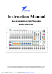
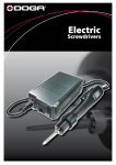
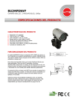
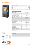
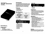
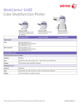
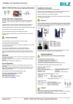
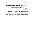
Introduction
Thank you for purchasing a RiMELITE product. The i-series battery built in strobe incorporates some
of the advance features in its lightweight and compact design. We are ascertain that you are excited
to start using the strobe right away. However, it is important to spare a 10 minutes to read through
this Manual first to handle the strobe correctly.
This strobe is primarily designed for on location photographer and photographer that travels to various
country with different AC voltage output. The built in high capacity Lithium ion battery hold sufficient
power to fire up to 600 Flashes at Full Power of 400w of i4 on a fresh full charge battery. This
should be sufficient for a normal shooting for a day before looking for an electricity outlet to charge
the strobe again.
Safety Instructions
1) The strobe (aka, flash unit) is designed exclusively for photographic use only
2) Never fire a flash in the vicinity of flammable gases or liquids! Danger on Explosion!
3) Never fire the flash to people or animal in the immediate vicinity of the eyes. It might damage the retina
and lead to severe visual disorder (including blindness) at close range.
4) Never fire flashes towards moving vehicle or people. They could be blinded by the flash and cause an
accident
5) Do not expose the strobe under excessive heat source such as hot sun or fire. Danger of explosion on the
battery.
6) Protect the strobe from excessive heat and humidity.
7) Do not touch the flash tube with bear hand especially after flash shots, as you may damage the tube and
burn yourself!
8) Allow at least 2 minutes interval after taking a series of 10 full light output shot in rapid order.
9) Never use charger with different specification to charge the strobe.
10) Do not over charge your strobe as it may damage the battery cells and cause explosion hazard.
11) Never try to open, repair and/or modify the strobe yourself. DANGER: High Voltage inside! Seek your
local dealer for assistant should you encounter problem with your strobe.
i.2 / i.4 User Manual
1. Control Dial for Flash Power .
2. Control Dial for LED Modeling Light.
3. RPT - Stroboscopic (C Mode) Button.
4. Short Flash Duration (T Mode) Button.
5. Cell On/Off Button.
6. Ready Charge Beep On/Off Button.
7. Test Button.
8. Main Power On/Off Switch.
9. Sync Socket 6.3 mm Jack.
10. Charge Jack /5.5 mm For The Battery.
11. Battery Power Level Indicator.
12. Battery Status
13. Main Digital FND Display.
14. Standard RiMELITE’s Receiver Slot.
15. Photo Cell.
16. Handle
17. Swivel Tigthening Knob
Initial Setup
The i-series flash unit ships with a Hard Plastic Protective Cover, in place over the flashtube and Pyrex
Glass Dome to protect these items in transit. The Plastic Cover must be removed before using the unit.
The battery is not fully charged direct from the factory. To ensure optimum battery lifespan, kindly charge
the battery for approximately 8 hours for the first time before using. To charge the i-series;
1) Connect strobe with the Charger to an electrical outlet (110v-240v).
2) The LED Battery Status (12 on page 2) indicator will change from Charge to Full once it is fully charged.
Please perform the following for the preliminary testing for your strobe;
1) Turn the Control Dial for Flash Power (1 on page 2) to the Right to increase the Power output and Left to
reduce the Power Output (Check the FND Display and the numerical number should change according).
2) Press the Test Button (7 on page 2) to test fire the flash
(CAUTION: Avoid looking at the flash tube or pointing it to people or animal at close range while testing the
strobe. It will cause severe visual disorder including blindness)
Flash Modes
The i-Series comes in 3 modes of shooting; Normal Mode, High Flash Duration Mode and Stroboscopic
Mode. Therefore a clear understanding of the various mode is important before using the strobe.
Normal Mode
Ÿ This is the standard mode for the strobe.
Ÿ Turn the Flash Power Control Dial (1 on page 2) to the Right to increase the power or to the Left
to reduce the power
Ÿ The Highest power is indicated as 7.0 in the FND display
Ÿ The Lowest power is indicated as 1.0 in the FND display
Ÿ The strobe allow user to make fine adjustment of 0.5 step.
Model
F 7.0
F 6.0
F 5.0
F 4.0
F 3.0
F 2.0
F 1.0
i2 (200w)
200w/s
100w/s
50w/s
25w/s
12w/s
6w/s
3w/s
Colour
Temperature
5380 k
5430 k
5420 k
5330 k
5420 k
5440 k
5440 k
i4 (400w)
400w/s
200w/s
100w/s
50w/s
25w/s
12w/s
6w/s
Colour
Temperature
5420 k
5480 k
5560 k
5600 k
5590 k
5550 k
5500 k
“T” or High Flash Duration Mode
Ÿ This is the mode designed for a shorter flash duration for high speed photography purpose (such as
water droplet)
Ÿ To change the strobe from Normal to “T” mode, press the Mode button (Button 4 on page 2)
Ÿ The FND Display will change from Numerical to t1, t2…t7 based on the memory of the last input
value
Ÿ Turn the Power Control Dial to its right to increase power or slower flash duration (1 on page 2) and
to the Left for lower power or fast flash duration.
Ÿ The Sowest Flash Duration is indicated as t7 in the FND display (The highest flash power output)
The Fastest Flash Duration is indicated as t1 in the FND display (The lowest flash power output)
Model
t7
t6
t5
t4
t3
t2
t1
i2 (200w)
1/500s
1/640s
1/1250s
1/2500s
1/4000s
1/6400s
1/12800s
Colour
Temperature
5300 k
5300 k
5340 k
5450 k
5550 k
5750 k
6300 k
i4 (400w)
1/500s
1/640s
1/1250s
1/2500s
1/4000s
1/6400s
1/12800s
Colour
Temperature
5300 k
5300 k
5450 k
5450 k
5500 k
5700 k
6200 k
*The flash duration above measured in t0.5 and Colour Temperature in Kelvin.
(CAUTION : The strobe will store a higher power in the “T” mode. Therefore, switching the “T” mode back
to Normal Mode might result a over charge flash output. Please press the Test button 2 to 3 times to
dump all the excessive power before continue the shooting)
“C” or Stroboscopic Mode
This mode is dedicated to fire a series of High Speed flashes (5fps, 10fps or 15fps)
5fps
10fps
15fps
For the “C” mode, user can either select the “C1” for lower power flash output or “C2” for higher power
flash output.
Please follow the steps below for engaging the “C” mode
Ÿ Make sure the flash power output is either 1.0, 1.5, 2.0 or 2.5 in the normal mode or t1 and t2 in
the Flash Duration Mode.
Ÿ Press the RPT button (3 on page 2) after select the appropriate power setting. The FND display
will show “C1” or “C2” to indicate the power setting.
Ÿ By default, the flash will fire 5fps. To set the strobe to fire 10fps or 15fps just press the RPT button.
5fps
10fps
15fps
(NOTE : The Flash Duration & Colour Temperature of the flash when performing in the “C1” or “C2”
mode is similar to “t1” and “t2”)
Modeling Light
The i-Series uses 2.5w dimmable LED for its modeling light. User can control the brightness by turning
the control knob (2 on page 2) to the right to increase the brigthness.
Cell / Slave Mode
Press the Cell button (5 on page 2) to turn on the photocell sensor.
Sound
Press the Sound button (6 on page 2) to turn on the audible (“Beep” sound) indicator for the charged
signal. (NOTE: its only work when the flash is operate in the Normal Mode)
Test
Press the Test button (7 on page 2) to test fire the flash. The Yellow colour LED on the Test Button will go
off right after the flash discharged and light up again when its charged and ready to fire.
Sync Socket
The flash support a standard 6.35mm Sync Cable Cord.
Standard RiMELITE Receiver Slot
I-series support both Swing System I & II. Remove the plastic cover and insert the Swing Receiver
module to slot gently. The indicator light on the Receiver will light up once the Flash power is On.
Specification
Model
unit
i2
i4
Flash Power
J(J/W)
200
400
22
32
Power range(W)
6~200
12~400
Variable Range of flash
6 F-Stop (0.5 Stop incremental)
F-Stope,1m,ISO100,With hard type reflector: RST-164H
Recycling,max
2.5
3.7
Recycling,min
0.01
0.02
Flash Duration (t0.5) @ min : max (T- Mode)
1/12800 : 1/500
1/12800 : 1/500
Flash Duration (t0.5) @ min : max (F-Mode)
1/3700 : 1/690
1/2750 : 1/500
Color Temperature(+/-200) ; Base on F-mode
5,450k (+/-150)
Flashes with full charge battery (+/-10) @ Max power
1000
550
Flashed with full charge battery (+/-50) @ min power
9000
4500
Voltage Stabilization
Sync voltage
Flash Power Control
Max.
V
0.1% stability for digital Image
10V (+/- 1V)
Encoder Knob Volume System/Swing II
Remote controller system
Modeling Lamp
Battery (Li-ion)
Charger for battery/ charge time
Remote controller(Swing II)
Weight(Kg)
Dimension(H x W x D mm)
Main fuse
Triggering system
2.5 W LED
12V 10A (old) 11.1V 8.8A (new)
AC100V~AC230V input
output / 4~5Hour
12.6V
2A
2.4Ghz 6groups & 16 Channel Each Group
The max 96 strobes can control.
2.5Kg
2.7Kg
120 X 118 X275
30A
Sync cord(6.3mm jack), Swing I , Swing II
Recommended Accessories
Swing II (Wireless Remote control and Flash Triggering System)
The Swing II is the latest in the Swing System family. Its inherited the sleek design, stable signal and high reliability.
The new Swing II comes with wireless control of the power setting of your flash. It allow user to control the flash
power output (On/Off, Increase/Reduce Power) up to 96 strobes wirelessly.
Swing II Receiver
2.4 Ghz
6 Groups Setting with 16 Channels per group
Strobe No. Display in the LED counter
Individually set by User
Swing II Transmitter
2.4 Ghz frequency.
Sleek Design.
Use only 1 AA Battery (1.5V).
Maximum Range: up to 180m.
Effective Range: 80m.
Effective Sync Speed: up to 1/250s
SpeedBox
Easy folding and super fast setup
Single layer double Rib (RiMELITE’s material) diffuser
Standard Speedlite Bracket & Bowen Adapter