1
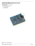
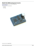
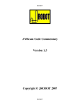
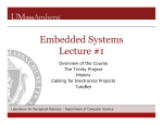
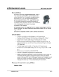
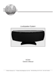
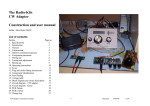
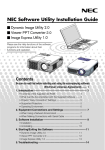
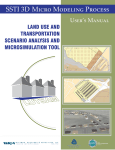
PolyBot Board: a Controller Board for Robotics Applications and Education
John S. Seng
Dept. of Computer Science
California Polytechnic State University
San Luis Obispo, CA 93407
[email protected]
Abstract
In this paper, we discuss the design and engineering
of the PolyBot board, a custom robot controller board.
This board has many features which make it suitable for
use in the design and construction of a simple mobile
robot. We outline the design decisions made such as: microcontroller selection, input and output features, board
layout, connector selection, and software. We discuss
our experiences in using the board in an undergraduate robotics class at Cal Poly State University, San Luis
Obispo.
1. Introduction
Robotics is a multi-disciplinary field of growing importance. When integrated into an undergraduate engineering curriculum, a robotics course can provide
an invaluable learning experience. Students studying
robotics are not only exposed to strictly software or
hardware problems, but also the challenges that arise
from interactions between software and hardware.
At California Polytechnic State University, San Luis
Obispo, the computer engineering department offers a
course in autonomous mobile robotics. This course
is taken by computer science, computer engineering,
and electrical engineering students. One goal for the
course was to teach students the robot-building process
by incorporating both an electrical engineering and computer science experience. In the process of constructing a robot, the students gained an important experience
in learning and understanding the interactions between
robot hardware and software. The lab component for
this class was crucial. Since one of the goals of the
course was to teach engineering students how to build
simple autonomous mobile robots, the approach was to
have students build their robots from the ground up. A
primary goal was to have the students fully understand
the hardware of the robot controller board they were
given.
We wanted to find a board that was easy to use, had
good functionality, was relatively inexpensive, and had
free open-source software tools. To meet these requirements we decided to implement our own custom robot
controller board, the PolyBot board.
This paper outlines the design decisions made when
engineering the PolyBot board. We cover the process
of selecting a microcontroller, designing the board to
protect against damage during use, and features that
are often required when designing small mobile robots.
In addition, this paper covers our experiences in using
the PolyBot board for a recent undergraduate robotics
course.
This paper is organized as follows: Section 2 covers related prior work. Section 3 covers design decisions made during the development of the PolyBot
board. Section 4 discusses selecting a microcontroller
for a robot controller board. Section 5 describes the connectors used on the PolyBot board. Section 6 describes
how software is downloaded to the board. Section 7
outlines the documentation and software support for the
PolyBot board. Section 8 covers our experience with
using the PolyBot board during a recent robotics course.
Section 9 describes future work. Section 10 concludes.
2. Related Work
The PolyBot board is similar to a number of robot
controller boards on the market today. Small robot controller boards typically include support for a number of
analog and digital sensors, some interface circuitry for
DC motor control, and some sort of user output (whether
it be an LCD display or simply a few LEDs). Some example small robot controller boards include the Handy
Board, the OOPIC-R board, and Basic stamp microcontroller modules.
The PolyBot board combines and enhances many
of the ideas present in the Handy Board [7]. The
Handy Board has proven to be very successful for use
in robotics classes [6, 5]. Some differences between the
PolyBot board and the Handy Board include: the use of
a faster microcontroller, the addition of external servo
and motor power ports, extra analog inputs, configurable
power input, and power polarity protection.
The OOPIC-R [10] robot controller board provides a
more direct interface to the digital I/O pins and provides
more servo output ports. It is a smaller board without
support for direct physical attachment of an LCD display.
Figure 1. PolyBot board with LCD display.
Figure 2. PolyBot board without LCD display.
A Basic Stamp [9] module provides excellent software support and programming interface, but is not integrated into a robot controller board providing support
for direct actuator interfacing such as DC motors.
3. PolyBot Board
The PolyBot board is a controller board developed at
Cal Poly for robotics education and applications. The
PolyBot board has the following features:
• physical size is 3”x4”
• 16MHz ATMega32 microcontroller
• 8 digital inputs
• 10 analog inputs
• 8 hobby servo outputs
• 4 DC motor outputs
• 1 software-controlled LED
• 16x2 LCD display with backlight
• 200mA relay/solenoid port
As previously discussed, the design for the board
was inspired by a number of different robot controller
boards, but all of the available boards considered had
positive aspects and negative aspects. We decided that
no one available board would meet our needs as a robot
controller board. As a result, we designed the board considering the most common and required features for a
small mobile robot design. Figure 1 shows the board
with the LCD display mounted and Figure 2 shows the
board without the display.
In addition to the previously listed functionality, we
chose to design a board around the following desired criteria:
• All ICs must be in a DIP package
• All ICs must be socketed
• Built-in support to run board logic, servos, and DC
motors at different voltages
with little or no soldering experience can assemble a
board with chips with DIP packaging.
Another important consideration when developing
controller boards for student use is having socketed integrated circuits which isolate the sensor inputs from the
microcontroller. Having this isolation prevents incorrect sensor wiring from directly damaging the microcontroller. This situation is not excessively important when
a microcontroller is as low cost as the ATMega32, but in
cases where the microcontroller is more expensive, this
needs to be considered. In our design, we are able to isolate all the digital inputs and most of the analog inputs
from direct connection to the microcontroller pins. We
were able to use chips in a DIP package for the analog
and digital inputs.
Robot designs often use motors that require a voltage
level different from the voltage for the logic. Because of
this, it was important to have a board that supported supplying the logic at one voltage and running the motors at
a different voltage. This not only enhances flexibility
in the design, but allows isolation of noise between the
logic and motors.
Finally, because the boards would be used in a student environment, it was designed such that the power
input was tolerant of a number of mistakes that could be
made in powering the board. Firstly, the board should
have a fuse to prevent damage should a short occur. A
motor may be stalled or a sensor may be wired incorrectly and these events should trip the fuse. Secondly,
the board needed to be able to withstand a reverse polarity power connection. If someone inadvertently connects power and ground backwards to the board, the
board should be able to tolerate such a mistake. To
achieve our goals of input power protection, we use a
PPTC resettable fuse (1.85A) coupled with a 1N5401
diode. The diode does not conduct when the power is
applied correctly (this provide normal protection against
over-current situations). When power is applied incorrectly, the diode conducts through the fuse, which trips
the fuse and stops the flow of current.
Other features present on the board include: a jumper
to allow enabling/disabling of the LCD display backlight (JP BL in Figure 3), a software readable push
button (SW1), a software readable potentiometer, a 2pin header which can control a relay (supplies up to
200mA), and a software controllable LED.
• reverse-polarity and over-current protection
All integrated circuits needed to be available in a DIP
package because it was planned that the students would
assemble the controller board as a lab assignment in the
class. Although the trend in integrated circuit packaging is toward smaller and smaller packages, a DIP package makes sense for a student controller board. Students
4. Microcontroller Selection
Several microcontrollers were considered for the
PolyBot board. The Atmel ATMega32 [3] was selected
for a number of reasons. The first reason is because of its
high performance. Although the microcontroller clock
rate is 16MHz, the CPU core is RISC based and delivers
performance close to 1 MIPS per MHz. Secondly, the
fastest version of this microcontroller is available in a
DIP package. Again, the importance of the chip package
cannot be overlooked because this is a board that will be
used by students in various environments with various
sensors and replacing a damaged microcontroller should
be an easy task. Thirdly, the software tools available for
the microcontroller are open source and run on multiple platforms. The compiler is based on GCC and the
toolchain is based on GNU tools. The compiler available
is called AVR-GCC [1] and runs on Windows, Linux,
and Mac.
jumpers used to connect/disconnect the external motor
and servo power from the power applied to the power
jack. Two jumpers are used for each connection to handle higher currents. In Figure 1 and Figure 2, the board
is shown with the jumpers installed.
5. Connectors
For the download cable connection, we use an RJ-45
connector. This type of connector was chosen because
of the positive locking it provides with repeated connects
and disconnects.
Connector selection is an area that deserves careful consideration when designing equipment for student
use. Firstly, connectors need to be durable and reliable,
especially after repeated connects and disconnects that
students perform when testing their robots. Secondly,
the connectors also need to provide flexibility in the
overall design. Robot designs should not be particularly
limited or restricted because of the number or type of
available connectors. This section describes why particular connectors were selected on the PolyBot board.
Figure 3 is a diagram showing all of the connectors on
the PolyBot board.
For the main power input, we selected a standard
2.5mm inner diameter jack (5.5mm outer diameter).
This power jack allowed the design to eliminate a power
switch from the board. A user can quickly remove power
by pulling the plug from the jack. JP PWR is a 3-pin
male header which allows a user to enable the on-board
5 volt regulator. If the regulator is enabled (via a shorting jumper), the board may be powered with 7V-20V.
If a user disables the regulator, then the board must be
powered with exactly 5 volts.
The PolyBot board provides support for connecting
up to 8 hobby servos. Hobby servos typically come
with a 3-pin (5V power, ground, and signal input) female header with .1” spacing. This standard spacing was
used on the PolyBot board. For each of the RC servo
connectors on the board, we use a 3-pin male .1” spacing connector. This provides a very positive and durable
connector for the servos.
For the DC motors, we use 3.81mm spacing screw
terminal type connectors. These were selected because
of the higher current that they can carry and because
they allow for different sizes of wire to be used for the
motors. For the DC motor and servo external power inputs, we also use the same 3.81mm spacing screw terminal connectors. There are standard .1” spacing shorting
For the analog and digital inputs, we use connectors
similar to the HandyBoard [7]. The connectors are 3 pin
connectors with a +5V, ground, and an input pin. This
type of connector works well because it allows sensors
to be moved among the different input pins without having to re-wire the sensor leads. There is also an 8 pin
digital I/O header which provides access to +5V, ground,
and 6 digital I/O pins. A 4 pin header allows access to
the SPI port.
6. Downloading to the PolyBot board
Program download is performed over the parallel port
through a download board. A picture of the download
board is shown in Figure 4. The board provides an interface between the parallel port and the SPI port of the
ATMega32 (which is used in programming the chip). A
10-pin IDC connector is located on the right end of the
board (as shown in the figure) and is used to connect the
board to a computer parallel port. A standard Cat-5 Ethernet cable is used to connect the download board to the
PolyBot board. The download board contains a CMOS
buffer (74HCT541) which is used to maintain signal levels from the parallel port to the controller board. Two
LEDs indicators are provided on the download board to
indicate connectivity and data transmission status.
As an alternative to downloading through the parallel
port, we developed a bootloader that allows downloading through an RS-232 serial port. This was possible because the RX and TX serial lines of the microcontroller
are also routed to the RJ-45 jack. When this bootloader
is installed, holding a pushbutton switch and pressing
reset enables the serial download mode. With the availability of USB to serial converters, we found that this
was a very useful option for those users who do not have
access to a computer with a parallel port.
For the software to perform the downloading, we use
the open source download program, AVRDude (AVR
Downloader/Uploader) [4]. This program allows reprogramming of the fuse configurations bits and the program flash memory.
Figure 3. Connectors on the PolyBot board.
7. Documentation and Software
We have written a user’s manual [11] for the PolyBot board. Because the PolyBot board comes as an
unassembled kit, the user’s manual not only includes information regarding usage of the board, but it includes
board assembly instructions.
For software support, we have written a software library for the PolyBot board. This library includes function calls to read the analog and digital inputs, control
the servo outputs, control the motor outputs, and display
information to the LCD display. We have found that providing a library greatly improves quality of the students’
robots. In addition to the library, students can modify all
of the microcontroller pins and configuration registers
directly from their C code.
8. Course Experience
We use the PolyBot board in an undergraduate mobile
robotics course. This course is intended to introduce students to concepts in the design and construction of autonomous mobile robots. The course enrollment comprises of students majoring in computer science, computer engineering, and electrical engineering.
For the class, each pair of students receives the PolyBot board as an unassembled kit. The kit comes with a
PolyBot board printed circuit board, a download printed
circuit board, and all the necessary components to populate the circuit boards.
The first laboratory for the class is to assemble the
PolyBot board. Even though students taking the class
entering with a wide range of experience levels in soldering, all of the students have been able to successfully assemble their PolyBot board kits. Students with prior soldering experience can readily assemble the board. When
having students assemble the boards, it is important to
perform a pre-check process before they continue. Have
the students first solder on the chips, but only 2 pins that
are diagonally opposite. After they have attached all IC
sockets in this manner, check to make sure the sockets
are correct. If all sockets are correctly then allow them to
proceed. Performing a pre-check in this fashion allows
easy removal of sockets if they were installed correctly.
We have had very high success rates with student board
assembly.
For the robot chassis, we use the ScooterBot platform
from Budget Robotics (www.budgetrobotics.com). This
chassis consists of 2 circular pieces of expanded PVC
connected with tall aluminum standoffs. This chassis
the microcontroller and can be off-loaded to a smaller,
secondary microcontroller.
The current PolyBot board has met our goals for
functionality. For a next generation PolyBot board we
intend to include the following features:
• Dual I2 C ports
• Dual UART ports
• Higher performance microcontroller
• Larger flash memory and SRAM
Figure 4. The download board used to program
the PolyBot board.
provided a well constructed platform which was powered using hobby servos. The hobby servos were already
modified to provided 360 degree rotation. The hobby
servos provided more than enough torque and speed for
the applications the students were targeting.
Some of the lab assignments in the class included the
following: analog and digital sensor interfacing, PID
line following, vision-based color detection (using the
AVRCam [8]), and shaft encoder implementation.
In addition to using the board in the mobile robotics
class, we also sell the unassembled kits to students. As
a service to the students, the kits are sold at the cost of
the parts and provide them with a source of low cost
development boards for outside projects.
9. Future Work
The current version of the board uses a parallel port
for downloading and the standard parallel port is being phased out as more and more computers switch to
providing only USB ports. We provide to the students
a bootloader that can be used (along with another circuit) to download a program to a board using a standard
RS-232 serial port or a USB-to-serial cable. We have
found that this solution works well for those students
with computers without a parallel port. We are working
on a USB-to-RJ45 download board which will be backward compatible with existing PolyBot boards.
In addition, we are considering adding another microcontroller to handle the servo and motor control. These
functions require a significant amount of CPU time from
The architecture we will use will be the ARM7TDMI.
There are many microcontrollers based on this CPU
core. These include microcontrollers from Analog Devices, SGS-Thompson, Atmel, and Philips. We intend
to use the LPC2138 from Philips [2]. The reason for selecting the LPC2138 is that it comes with a bootloader
in hardware that allows downloading over a UART serial
port.
Since this is a surface mount chip with tight pitch,
the microcontroller will be already soldered to the board
before distributing the kits to the students. In order to
prevent damage to the microcontroller, we intend to use
other socketed chips as interface chips. If the damage
occurs to one of these interface chips, then it can be easily replaced with no damage to the LPC2138.
The current board does not allow for RAM storage,
and this is something we would much like to see in a
next generation board. The LPC2138 provides 32KB of
static RAM and 512KB of program flash memory. These
increases in memory size over the ATMega32 will allow
more advanced work such as operating system development on this platform.
Other future work we intend to pursue is to develop
audio and DSP daughter cards for the PolyBot board.
This will allow us to use the board in classes other than
the introductory robotics course.
10. Conclusion
The PolyBot board is a controller board that was designed at Cal Poly State University for robotics education. The board was designed with the goals of being
easy to use, buildable by students, providing good functionality, and having a low cost.
The PolyBot board has an Atmel ATMega32 microcontroller, a number of analog and digital inputs, several
hobby servo and DC motor outputs, and an LCD display.
The total cost for printed circuit board manufacturing
and parts has been very reasonable for use in a university
environment. By developing the board and purchasing
the parts in quantity, we were able to significantly reduce
costs.
We have used the PolyBot board in an undergraduate robotics course at Cal Poly State University. This
board has been successful in providing students with a
platform to build small, mobile robots.
References
[1] AVRGCC - GCC port to the AVR architecture [Online]
Available http://winavr.sourceforge.net/.
[2] Philips
LPC2138
Single
chip
16/32
microcontroller
[Online]
Available
http://www.semiconductors.philips.com/pip/LPC2132FBD64.html.
[3] Atmel Inc. Atmel ATMega32 8-bit AVR Microcontroller with 32KB In-System Programmable Flash [Online] Available http://www.atmel.com/products/avr.
[4] B. Dean.
AVRDUDE - AVR downloader/uploader
[Online]
Available
http://savannah.nongnu.org/projects/avrdude.
[5] S. Imberman. Teaching neural networks using lego
handy board robots in an artificial intelligence course. In
Proceedings of the 34th SIGCSE technical symposium on
Computer science education, May 2003.
[6] D. Kumar and L. Meeden. A robot laboratory for teaching artificial intelligence. In Proceedings of the 29th
SIGCSE technical symposium on Computer science education, May 1998.
[7] F. Martin. The Handy Board Technical Reference [Online] Available http://www.handyboard.com.
[8] J. Orlando.
The AVRCam [Online] Available
http://www.jrobot.net/Projects/AVRcam.html.
[9] Parallax Inc.
Basic Stamps [Online] Available
http://www.parallax.com.
[10] Savage Innovations. OOPIC - The Object Oriented PIC
[Online] Available http://www.oopic.com.
[11] J. Seng. PolyBot board user’s manual [Online] Available
http://www.csc.calpoly.edu/j̃seng/PolyBot Board.html.