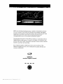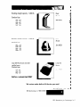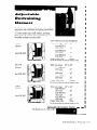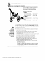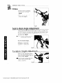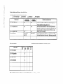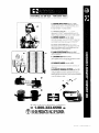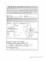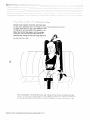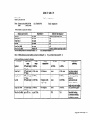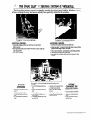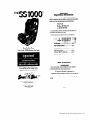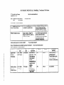
1
Adaptive Seating Designed for
Occupant Protection Use
Adaptive seating
designed for
occupant protection use
Adaptwe
Seatmg
designed
for occupani
protection
use
paye
1 of 2
07/22/1999
03:
17
6143744501
EASTER
SEAL
MARIETTA
Warning!
Manufacturer
instructions
constant revision.
are under
These are current instructions for
models currently in production (as of
5/99) ONLY.
This section DOES NOT include:
models no longer on the market (but
still in use), previous versions of
instructions for current models.
Alwavs consult with the manufacturer
to confirm that instructions are
matched and appropriate for your
product’s model, serial number and
date of manufacture.’
Adaptive
Seating
deslgned
for occupant
protectlon
use
page
2 of 2
PAGE
05
BESI Manufacturing,
http://www.besi-inc.com
9445 Sutton Place
Hamilton, OH 4501 I
Phone:
Customer
Other
Product family
Infection
Inc.
service (800) 543-8222
(513) 874-0232
Faxes: (513) 8X-0579
E-mails:
www.besi-inc.com
at a glance for clinicians:
control protocols or warranties
History of Medicaid/insurance/state
Product specifications
m
m
m
.-
available?
disability
If yes, description
purchases for individuals?
attached?
If yes, roll call of states attached?
at a glance for clinicians:
RANGE
BR-22 AI
Small Harness
BR-30 AI
Medium Harness
BR-38 AI
Large Harness
22-28”
30-36”
Not Applicable
NO
Not Applicable
NO
Not Applicable
NO
I
38-44”
Product installation
Appropriate
_
specifications
at a glance for clinicians:
vehicle environments:
Cars, vans, pickups
(check any that apply)
X
School buses
-Ambulances
-
Price range categories:
Other manufacturer
comments
Other
(specify):
Purchasing
regarding
issues for medical/disability
clinicians
programs
and safety specialists?
for professionals
or community
programs:
BESI
Manufacturlny,
Inc
Products
page
I 01 17
42 oz. Standard
BESl’s
school
minimum
bus upholstery
standard
properties
302
Material:
bus seating.
jersey
backing
- fire retardancy
Sewn
#92
knit
standard,
with
with
pattern
meets
for school
utilizing
in conjunction
fabric
OEM
nylon
at 6 stitches
and
thread
using
per inch.
covers
302,
Cover
are sewn
a lock
stitch
are back
passed
Bag
FMVSS
222
burn
equivalent
in physical
the requirements
- impact
stitch
of FMVSS
standard,
when
used
test, Ath-891
sew
are back
all of the following
FAR-25-853B
with
meets
a lock
Fire block
and
It is a 42 ounce
and
All ends
and Proform/PrevaiU@
material:
FMVSS
of the national
foam.
Kevlar@
frreblock
spec.,
the requirements
stitched.
burn
(fireblock),
tests:
Ky. bus
(fireblock).
#92
sew pattern
bonded
kevlar
at 6 stitches
thread
per inch.
using
All ends
stitched.
Weight
Coating
Fabric
per square
weight
weight
yard
per square
yard
per square
26
oz.
18.5
oz.
7.5 oz.
yard
52 oz Material:
BESl’s
school
bus upholstery
minimum
standard
properties
utilizing
302
- fire retardancy
used
in conjunction
fabric
for school
jersey
knit backing
standards,
with
meets
OEM
the requirements
bus seating.
It is a 52 ounce
and
and
meets
FMVSS
of the national
equivalent
in physical
the requirements
222
- Impact
of FMVSS
standards,
when
foam.
Sewn with #92 nylon thread
using
inch. All ends are back stitched.
a lock
stitch
sew pattern
at 6 stitches
per
Seat Covers
BESI
Manufacturing,
Inc.
m
Products
page
3 of 17
Velcro
Seat Covers:
BESl’s
innovative
are easy
No
staples,
Pocket
BESl’s
velcro
to install,
screws
or rivets.
Barrier
driver
seat covers
in minutes,
Cover:
side
only
pocket
is designed
to to organize
loose
for a safer
items
cover,
designed
barrier
all those
ride.
A quality
for the customer,
features:
*Five
pocket
*Broom
design.
holder.
*Concealed
items
velcro
secure
@In velcro
enclosure
in pocket.
style seat cover
The pocket
barrier
only.
is available
BESl’s
complete
line
match
the seats
in your
available
to keep
of colors
in
to
bus. Also
in fire block.
All our seat covers
are tagged
the cover
Please
call
was
with
made
BESI
Seat Covers
mm
Manufactumg,
Inc.
Products
page
4 of 17
numbers,
by whom
for a list of popular
descriptions
I
part
and
description,
the cover
seat cover
for easy
ordering.
part
the month
was
sewn.
numbers
and
and
year
Seat Back Foam
Upholstery
Certified
l
For instant
l
3” x 60 yard
l
Available
brown,grey,
to meet
FMVSS
302
FMVSS
222
requirements
& model
and
for all make
buses.
Tape
seat
repairs
rolls
in green,
& blue
IIIIIIII
Vinyl Spray Paint
Color
it perfect
of graffiti
aerosol
and
when
hide
using
patch
our vinyl
work
spray
paint.
on seat covers.
Gets
rid
Convenieni
cans.
Colors available:
aThomas
Brown
@Thomas Green
*Thomas
Grey
l AmTran
l AmTran
l AmTran
l AmTran
l AmTran
Green
Chocolate
*Bluebird
*Bluebird
Brown
Green
*Carpenter
Dark
Blue
Grey
Green
Blue
Grey
Black
*Carpenter
Brown
Dark Green
Grey
*Carpenter
Blue
l Carpenter
Wayne
@Wayne
@Wayne
l
Seat Covers
BESI
Manufacturlrlg.
m
Inc Products
page
5 of 17
Safety
Belts,
Straps
and
Attachments
Our
belts
are constructed
with
type
602.4
breaking
strength
standard
automotive
meet
209,
stitch
Stitching
with
Our
belts
has several
types
belt
please
us a call we would
2 13,
of mounting
Item #0021
Inc.
Products
page
6 of 17
is
box X sew pattern.
302
and
hardware
be glad
Belt Assembly
Push Button
Release Buckle
and Attachment
fvlanufacllJring.
pounds.
safety
Inc.
give
FMVSS
2” nylon
The webbing
is 6,000
I
I
BESI
of strong
webbing.
each
belt
Thread
has a certification
available.
to work
Restraint
type
If you
with
you
need
to meet
is 207
nylon.
label.
a custom
your
BESI,
designed
needs.
System
Breaking
strength
capacity:
5,000
lb.
Breaking
strength
Standard
size:
capacity:
5,000
Floor
Mount
lb.
Item #0023
PBF - 60”
PBF - 45”
PBF - 70”
PBF - 75”
Breaking
strength
Standard
size:
capacity:
5,000
lb.
Seat
Mount
Item #0024
PBA - 60”
PBA - 45”
PBA - 70”
PBA - 75”
Loop
Belt Mount
certified
specs.
Standard
size:
does
Loop Belt
Mount
not meet
Item if0025
PBL - 60”
PBL - 70”
PBL - 75”
Sold as u resfruint
belt ONLY
We custom
make
belts
to fit the size you
need.
Seat Covers
BESI
Manufactumg.
m
Inc
Products
page
i’ of 17
Installation
instructions
How to assemble
Place
Buckle
around
loop
How to assemble
Bolt mount
I m-
BESI
Manufacturing,
Assembly
Inc. Products
Directions
page 8 of 17
a Loop Belt
bar and
through
on belt.
seat mount
to seat frame
belt
For Series E and A Track
2”“D” Ring
Breaking
strength
Working
load
capacity:
5,000
capacity:
lb.
1,600
Weight:
.12
lb.
Ibs.
Item if0026
Series E and A
Spring Loaded
Breaking
strength
Working
load
capacity:
4,500
capacity:
lb.
1,500
Weight:
.21
lb.
Ibs.
Item #0027
Square Snap
Hook
Item #0028
Pair Adjuster
Breaking
strength
Working
load
capacity:
capacity:
Weight:
*
*
.21
Ibs.
Item #0029
* Strength depends on type of webbing
Belts &Mounts
BESI
Manufacturing,
used
-
Inc Products
page 9 of 17
I
I
2
ii
I
I
I
I
I
I
I
I
I
I
I
I
I
I
I
I
I
I
I
I
Series A Track
Vertical
Manhcturing,
High
strength
steel;
12
steel;
11
steel;
12
steel;
11
Qa”ge
Item #0032
50,000
16.6
psi.
Ibs.
10 ft.
Series A Track
Vertical
Item #0033
Series E Track
Horizontal
Material:
High
strength
gauge
Minimum
yield:
50,000
Weight:
21.1
length:
10 ft.
Material:
High
psi.
Ibs.
strength
cP”cF
Item #0030
50,000
16.6
psi.
Ibs.
10 ft.
Series E Track
Vertical
Item #0031
Series A & E Truck
I mm
BE!3
Material:
Inc.
Products
page
IO ot 17
Material:
High
iF”cF
Minimum
yield:
50,000
Weight:
1 1.6
Length:
10 ft.
strength
psi.
Ibs.
Restraining
Certified
conjunction
2 13 when
in 3 color
Each size
the ability
to take the place of a car seat when used in
with a seat belt. Our Harness
meet FMVSS
used with a safety belt. The Harness
comes
coded
sizes; small, medium,
and large.
has 3 separate
zipper
inserts that give you
to adjust to any size child.
Color-coded by sizefor easy identification
SMALL
Harness
Waist
Item # BR-22AI
Product
size range
Waist
Item # BR-30AI
Product
24”
Insert #Bl-224
child waist
26”
Insert #BI-22-6
child waist
28”
color
Waist
Item # BR-38AI
Product
Brown
one
insert
per harness
30”
to 36”
Insert #BI-30-2
child waist
32”
Insert #BI-30-4
child waist
34”
Insert #BI-30-6
child waist
36”
color
code:
than
insert
per harness
38”
40”
Insert #BI-38-4
child waist
42”
Insert #BI-38-6
child waist
44”
code:
than
at a time.
to 44”
Insert #Bl-38-2
child waist
color
at o time,
Maroon
one
size range
Do not use more
Adjustable
code:
than
size range
Do not use more
LARGE
Harness
to 28”
Insert #Bl-22-2
child waist
Do not use more
MEDIUM
Harness
22”
Grey
one
insert
Restraining
BESI
per
harness
at a time.
System
Manufacturing,
111
lrlc
Products
page
Y ‘I of 17
installation
instructions
How to Install
Restraining
Harness
Unbuckle
safety
seat and
insert
and
backrest,
end
release
buckle
of seat mount,
end
leaving
between
hooks
on seat.
over
top of back
rest with
front
side
of backrest.
Fasten
back
of the seat.
with
zipper
side
Place
harness
on back
Lay release
upper
seat
lift bench
seat cushion
hooks
mount
to
at the
on passenger
Use only
one expander,
as needed.
Hook upper and lower D-rings,
securing
passenger
in seat. Pull adjusting
strap
on seat back
snug.
TheCuyahoga
Sliding
Seat
Shoulder
hooks
seat mount
is color
coded
.----------__________
-
BESI
Manufacturmg.
Adjustable
Inc
Products
page
Restraining
12 of 17
System
slide
along
to fit the height
to match
Mount
webbing
to adjust
of the child.
the harness
vest.
Webbing
Little
People
Restraint
System
Our “Little People” Restraint System
is designed to transport preschool
or handicapped
children safely and
comfortably.
It can be easily installed
any standard seat.
on
How to Install
Little People Restraint
The Cam-rap style system is designed
upper body mobility control.
to help with
Unbuckle safety release, lift bench seat and insert
buckle end between seat cushion and backrest.
Place child in restraint. Use buckle to secure
restraint on child.
These restraint
harnesses
are not seat belts nor me they designed
to provide
protection
Adjustable
in the event
of a collision
Restraining
BE.3
or sudden
stop.
-
System
Manufacturtng.
lrtc
Products
page
13 of 17
Notes
BE.51
Manufacturing.
Inc
Products
page
14 of 17
Notes
BESI
Manufacturing,
Inc
Products
page
15 c:)f 17
Notes
BESI
Manufacturing,
Inc.
Products
page
16 of 17
BESI Manufacturing,
9445 Sutton
Place
Hamilton
OH 4501
5138740232
Fax 513 874
8005438222
Web
site:
Inc.
1
0579
http://www.besi-inc.com
BESI
Manufacturing,
lnc
Products
page
17 of 17
INSTALLATION
Unbuckle safety
release, lift bench seat
and insert buckle end
between seat cushion
and backrest, leaving
hooks on seat. Lay
release end over top of
back rest with upper
hooks to front side of
backrest. Place
harness on passenger
with zipper side on
back. Use only one expander per harness, as
needed. Hook upper
and lower D-rings,
securing passenger in
seat Pull adjusting
strap on seat back snug
and affix excess strap
end with hook and loop
stitched on strap.
1
@ ,w,
INC. ?%~?&%:o,,
Toil
M8nuf8clurar
mf arrllfy
School
But sol?
Covtrr
andPwaen
lr
Rcrtrsin
BR-22
Fm9'
600-643~6212
In OH <..,....613-874-0233
FAX . .. .. ... .. 61Sd74.0579
SysPMI
61-22-Z
G-22-4
81-22-6 -
2” BESI RESTRAINT
INSERT FOR 22
4” BESI RESTRAINT
INSERT FOR 22
6” BESI RESTRAINT
INSERT FOR 22”.
22” BESI RESTRAINT W/ SEAT MOUNT
81-30-2
2” BE.51 RESTRAINT
INSERT FOR 30”
30” BESI RESTRAINT W; SEAT MOUNT
81-30-4
4’BESl RESTRAINT
INSERT FOR 30”
38” BESI RESTRAINTW/
81-30-6
6’ BE& RESTRAINT
INSERT FOR 30”
22"HARNESS,MOUNT,&3lNSERTS
,..
30” HARNESS, MOUNT, & 3 INSERTS
81-38-2
2’ BESI RESTRAINT
INSERT FOR 38
81-38.4
4’ BESI REiTRAlNT
INSERT FOR 38”
36”CIARNESS,
MOUNT,& 3 INS&
B1*38#6
6’ BESIRESTRAINT
INSERT
FOR38’
SM-100
SEAT MOUNT FOR BESI RESTRAINT
22” BESI RESTRAINT HARNiSS
ISR-3iJ
”
30” iiS1
HA-33
‘:
38” 13Ei REsTRA~
-k-22A
I3R-30A
”
13R-38A’
iw2AI
13R-3OAI
‘JR-%A\
--.
EXPANDERS
These rertralnt harnesser
are not seat belts,
nor are they designed to provide protection
in the event of a colllslon or rudden stop, Has
been tested and meets or exceeds FMVSS 213.
cme
in
RESTRAINT
ONLY
HARiJESS ONLY.
HARNESS ONLY
SiAi
MOUNT
three sizes: 2”, 4”, end 6’
BESI
School
Bus Seat
Covers
& Passenger
Restraint
Systems
page
1 of 1
COLUMBIA
P.O. Box 633
Pacific Palisades, CA 90272
Phone:
Customer
Ordering
Other
Product family
Infection
History
Medical Manufacturing
Corporation
http://www.columbiamedical.com
service (800) 454-6612
(800) 454-6612
(310) 454-6612
Faxes: (310) 305-1718
E-mails:
@[email protected]
at a glance for clinicians:
control protocols or warranties
of Medicaid/insurance/state
Product specifications
available?
disability
No
If yes, description
purchases for individuals?
Yes
attached?
No
If yes, roll call of states attached?
No
at a glance for clinicians:
Stroller
Base: #2100
Product installation
specifications
at a glance for clinicians:
Appropriate vehicle environments:
- X Cars, vans, pickups
(check any that apply)
X
~Ambulances
~Schoolbuses
Purchasing
Price range categories:
Product
Other manufacturer
Other (specify): Airplane
Under
$50
name
comments
regarding
%515200
mn-
S501-
$500
over
issues for medicaUdisability
clinicians
programs
and safety specialists?
for professionals
or community
programs:
INSTRUCTIONS
Columbia
even when your Columbia seat is unocqied, as a safely
precaution for yourself and other occupants.
* The harness must only be used with your complete seat. Do
FOR USE
Model #2000
IMPORTANT:
Please read these instructions carefully. Failure to
follow each of the following instructions can result
in your child striking the vehicle’s interior during a
sudden stop or crash.
Your Columbia seat is suitable for children up to GO” (152 cm)
in height and meets and exceeds the requirements of FMVSS
#213. This requirement is the U.S. Federal standard for car seats
for children up to three years old, and requires crash tests with a
35 lb (I G kg) test dummy at a 30 mph (48 kph) impact.
Ahhough Federal standards have not been established for
heavier body weights, Columbia seats have been crash tested
and successfully withstood impacts using a 102 lb (46.3 kg) test
dummy at 30 mph (48 kpb).
Your Columbia seat also meets and exceeds the requirements
CMVSS 213.3, the Canadian car seat standard. Canadian
consumers should carefully read the supplemental instruction
sbcot attached to the car seat harness. Canadian consumers
of
must use the supplemental
tether strap regardless
of the
occupmnt’s weight, as described
in the supplemental
sheet.
WARNINGS:
* Your Columbia seat is designed to tit a wide range of
children. To insure a proper tit for your own child, it is
important that your seat be correctly set up and installed before
using il for the first time.
* The Columbia car seat must not be used with:
+r Vehicle seats that face to the side or rear;
i”i Vehicle seats with backs that can fold forward in a
crash or sudden stop. Some seat backs automatically
lock in an emergency. Cheek your owner’s manual or
with your dealer if you’re not sure;
-fi Seating positions with belts that automatically
surround the passenger as the door is closed;
si- Seating positions with emergency-locking
seat belts.
Set the section below on seat belts to determine
your vehicle’s seat belts may be used
which
of
Sr For children between 65 and 102 pounds (29.5 kg and 46.3
kg), your Columbia seat must be secured with both your
vchiclc’s seat belt and the included tether strap.
* To mnintain its safety, if your seat or harness becomes
badly worn or damaged, or if your seat is involved in an
accident, regardless
of speed and regardless
how minor,
your Columbia
seat may no longer be effective and should
immediately
be replaced.
* Metal tabs, etc., can become hot inside a closed automobile
in Ux sun. To protect your child, check that the metal parts are
not too hot before putting your child in your seat. If you park in
UK sun, covering your seat with a blanket, towel, etc., will help
keep the metal parts from heating up.
* Heavy, loose objects are dangerous in your vehicle. Always
have your Columbia seat sccurcd with your vehicle’s seat belt,
not try to use the harness independently of your seat.
* The Federal government recommends that children under
twelve years of age ride in the rear seat. The center of the rear
auto seat is the safest seating position in most vehicles, fOllOWXl
by the passenger-side rear seat, and then the driver-side rear
seat. Use the center rear seat whenever possible. Make sure thal
the front seats are far enough away from your Columbia seat lo
minimize. the risk of your child striking them in an accident.
* Never leave your child unattended in your automobile.
WHERE
TO INSTALL
Passive restraints:
YOUR SEAT
seatbelts and airbags
Your Columbia car seat cannot be used in seals that have
“passive restraint”-type seat belts, such as any kind of selflocking seat belt that the passenger does not have to fasten
themselves. For example, some vehicles have shoulder belts that
slide into place automatically when the passenger closes the
door, and then slide out of the way automatically when the
passenger opens the door. Because the seat belt tension cannot
be properly controlled, your Columbia car seat must not be
used with this kind of passive restraint, or any other kind of
passive restraint system.
Your Columbia seat must not be used in seats protected by
airbags, unless your vehicle has a swilch to turn the airbag off
Passenger-side airbags can cause serious injury or death to
children in safety seats,
Placement Of Your Columbia
Vehicle’s Seat
Seat In Your
If the lip of your Columbia seat projects more than one inch
over the edge of your vehicle’s seat bench, then the seat bench is
too shallow, and your Columbia seat must not be installed in
that seating position.
Seat belts
Your Columbia seat is designed for use only with certain
kinds of lap or combination shoulder/lap belts. Read the section
below on seat belts to determine which of your vehicle’s seat
belts are suitable.
Lq) Belts
Lap belts that have no retractor, but rely on the passenger to
pull on the free end of the belt to set the lap belt to the proper
tension can be used to secure your Colmnbia seat&nply
altacl!
the locking clip as shown in Figure 1 once you have adjusted
th%tK7tfo the proper tension. Snug the locking clip within %,, of
&e buckle.
Another kind of lap belt feeds into and out of a retractor.
When you pull on the free end of the belt, if you stop pulling, or
allow the belt to go back into the retractor, the belt “locks up”
and can’t be pulled out any further until you let the belt go aII
the way back into the retractor. This kind of seat belt can be
to secure your Columbia seat.
Some lap belts only lock up when the nose of the vehicle
dips, for example, during an accident, or when the driver steps
on the brake. These arc “emergency-locking”
seat belts.
used
Columbia
Instructions
Model
H2000
page
1 vf 4
Because these belts cannot be properly secured, they must not
be used to secure your Cohuubia seat.
Combination lap and shoulder belts
“Continuous-Loop” lap and shoulder belts are those that
have a lock plate (the “male” part of the seat belt buckle) that
slides freely along a continuous piece of webbing running from
the hip to the shoulder retractor. These belts can be used to
secure your Columbia seat. Once the seat belt is snug, simply
attach the locking clip within l/2” (13 mm) of the lock plate as
shovvn in Figure 1.
Columbia seat. Adjust the length of the crotch strap with the
metal slide on the underside of the seat.The length of the crotch
strap should be adjusted so that the lap belt of the harness is
down over the bony part of your child’s hips, not over their sotI
stomach area. With the lap belt positioned correcUy over your
child’s hips, the buckle will be located quite low, where it
should be.
With the crotch strap adjusted, take up slack in the shoulder
straps with the metal slides on the back of the seat, and with
those on the front. By using the metal slides on the back of the
seat to control the belt length, you may adjust the harness SO that
the adjusters on the front shoulder straps rest on a comfortable
part of your child’s body, i.e., below the collarbone.
Using the fine adjusters on the front, adjust the length of the
harness for a comfortable tit. The harness must fit snugly for
proper protection. Adjust the tightness of the shoulder straps
so that you can tit one or two fingers (but no more) between the
shoulder strap and your child’s collar bone.
STEP 4: Location of Chest Clip
The chest clip acts to keep the shoulder straps from sliding
down off your child’s shoulders. Make sure that the chest clip is
even with an imaginary line drawn from armpit to armpit. lf it is
too high, it poses a strangulation hazard; ifit is too low, it will
not keep the shoulder straps in place.
Figure 1: Use o/the locking clip
Some combination lap and shoulder belts have what is called a
“sewn lock plate”. The lap belt is sewn to the side of the lock
plate (the “male” part of the seat belt buckle), while the
shoulder belt is sewn to the top of the lock plate. Each belt feeds
into its own emergency-locking retractor. Because the seat belt
tension cannot be properly controlled with these belts, they must
not be used to secure Cohunbia seats.
USE AND INSTALLATION
STEP 1: Operating
Your Car Seat Buckle
Pressing the red button will open the buckle. To fasten the
buckle, insert the two metal tabs into the top of the buckle until
they click into place. Never lubricate the buckle.
STEP 2: Adjusting
Shoulder Strap Height
Your Cohunbia seat has four pairs of precut slots, at
diGrent heights up its back. The shoulder straps must be used in
the slots located just above your child’s shoulders. If you need to
readjust the shoulder straps to different slots, feed the metal
slides on the back of your Columbia seat through the slots. To
feed them through the slots, first twist the black metal slides
sideways so that they will fit through the slots and push them
through the slots. Do not attempt to unthread the straps
from the metal slides to get them through the slots. Never
lubricate the adjusters.
STEP 3: Adjusting
Harness Fit
In adjusting the harness, the crotch strap is the first part to be
adjusted. Loosen the other straps and place your child in your
Columbta
Instructions
Model
#2000
page
2 of 4
STEP 5: Adjusting
Positioning Pads
the Head Pads and
The head pads may be adjusted for height. Located behind
and underneath each head pad is a plastic ball, attached to the
lace that passesthrough the head pad. Squeezethe button on
each ball and slide the ball up or down to change the height of
the head pads.
The height of the positioning pads is set by tying them into
place at the desired height. Simply run the lace through the
grommets at the appropriate height, and then tie the pad into
place.
STEP 6: Securing The Seat In your Vehicle
Your Columbia seat is designed to face forward in your
vehicle in an upright position. Your seat is held in place with
your vehicle’s own seat belt and, for children 65 pounds (29.5
kg) or above, with your vehicle’s own seat belt and the included
tether strap. Important: do not attempt to place your
vehicle’s seat belt around the front of your Columbia seat,
the way many infant seats are held in.
Thread your vehicle’s seat belt through the two metal tubes
on the side of your Columbia seat, as shown in Figure 2.
Connect your seat belt buckle and, while kneeling in your
Cohunbia seat, adjust your vehicle’s seat belt as tight as
possible to hold your Cohuubia seat in place. Ifthe seat belt is a
combination lap/shoulder belt, pull upwards on the shoulder
portion of the belt to tighten the belt, then install the locking
clip. Kneeling in the seat helps secure it; when you remove your
weight from the seat, your vehicle’s upholstery will spring back
into shape and keep the seat in place even more securely.
Make sure that the seat belt buckle lies to one side or the
other of a side tube, not resting across it.
Note: the parcel shelf must be fixed and made of metrl
underneath. You can tell ifit is made of metal underneath by
looking in the truok. If the parcel shelf is adjustable or is not
metal underneath, follow the instructions for a hatchback, van,
or station wagon; in these cars, the tether anchor bolts to the
cargo floor. See Figures 3 and 4.
WARNING:
before drilling any hole in your vehicle,
make certain the gas tank, pipes, cables, etc., are not in the
way and will not be damaged. The tether anchor must be
mounted directly in a secure metal panel. If necessary for
access, trim the carpeting, hardboard
parcel shelf, or other
trim for clearance. Make certain that the tether webbing
does not rub against any sharp edges.
Sedans built 1989 or after, with a fixed rear
parcel shelf:
Figure 2: Securing Columbia
STEP 7: Installing
seat with vehicle ‘s seal belt
The Locking
Clip
-k Install your seat as described above, us&g your vehicle’s
scat belt.
* Hold your vehicle’s shoulder/lap belt webbing and the seat
bell tab to stop it from sliding. Then release the tab from your
scat belt buckle.
* Fold the webbing and thread it through the locking clip, one
side at a time. Keep the locking clip as close as possible to your
scat belt tab - no furtlier than %” away.
* Snug the clip against your seat belt tab. See Figure 1.
* Buckle your seat belt to see that the clip has been correctly
installed, with all slack webbing gone and the seat tightly in
place.
USE OF THE TETHER
STRAP
Mounting nut: Most cars built after 1989 or after, feature a
manufacturer-installed
tether mounting nut welded to the
underside of the parcel shelf. Because of its location, this
mounting nut is not normally visible. To find it, open the trunk
and look up at the bottom of the parcel shelf. Some cars have
one mounting nut, while others will have more than one. If your
vehicle has such a nut, use it. Insert a pointed object (nail, etc.)
into the nut from below, and up through your parcel shelf
carpeting. From the other side, using the protruding object as
your guide, trim a small hole in the carpeting. This will allow
the tether bolt to screw into the nut from above. Attach the
anchor as shown in Figure 3.
Sedans built before 1989, with a fixed rear
parcel shelf:
Cars built before 1989 generally will not have manufacturerinstalled tether mounting nuts. Instead, you’ll need to drill a
7116” hole and use the nut supplied with the tether. With your
Columbia seat in your vehicle, mark a spot on the center line of
your Columbia seat about 8” behind the seat, on the parcel shelf.
Open the trunk and, using a flash-light if necessary, inspect the
A tether strap is supplied with your Columbia seat. For
children between 65 and 102 Ib.( 29.5 and 46.3 kg), this tether
strup must be used in addition to your vehicle’s seat belt.
USC of the tether is optional for children under 65 lb.( 29.5 kg),
bul Columbia recommends that the tether be used regardless of
your child’s weight. Use of the tether will enhance the stability
of your Columbia seat for any weight child, particularly if your
vehicle has very soft or very upright seats. If you use the tether
strap, install it in your vehicle as instructed below.
INSTALLING
THE TETHER
The tclier strap is ‘V-shaped.
The bottom of the “V”
attaches to your vehicle. The hvo top ends attach to your
Columbia seat by hooking onto metal brackets located on Ihe
upper ends of each metal tube on the sides of your Columbia
scat. The metal anchor plate on the bottom of the “V-shaped
lclhcr must be bolted to your vehicle.
Where to install the tether anchor depends on your vehicle, If
you are installing your car seat in a sedan, the anchor plate bolts
lo the parcel shelf in front of the rear wmdow.
Figure 3: Tether anchoring
on parcel shelf
Columbia
Instructtons
Model
#2000
page
3 of 4
bottom of the parcel shelf. Make sure there are no dangerous
obshuctions underneath the spot that you have chosen. If it is
clear, drill a hole for the anchor bolt. Attach the tether anchor as
sllown in Figure 3.
Pickup trucks
can install your Cohunbia seat in the passenger-side front
seat only if there is no airbag on that side (or if the airbag can
be switched ofT). If your pickup truck has a rear seat, install
your Columbia seat there. You can install the tether in the rear
wall of the cab, a few inches below the rear window.
YOU
Attaching
the tether to a rear seat belt
You can attach your Columbia seat’s tether to the seaf belt of
the seat behind it, but only if the seat belt is one of the usable
kinds described above. You may need a second locking clip to
secure that seat belt. Tllis is a good option when installing in
minivans and some school buses, when you cannot easily reach
the floor of the vehicle.
Connecting
the tether strap:
With your Colmubia seat in place in your vehicle and the
seat belt firmly tensioned, hook the tether onto the metal
brackets on the upper ends of your car seat’s side tubes. Cinch
the tether tight with the tether strap adjusters.
Figure
4: Tether anchoring
on vehicle floor
Hatchbacks, vans, station wagons, and sedans
without a fixed metal parcel shelf:
With your Columbia
seat in your vehicle, mark a location on
the center line of the seat and far enough back so that the tether
slrap will create no greater than a 45-degree angle from the
horizontal (the floor of your vehicle). See Figure 4. Look under
your vehicle and make sure there are no dangerous obstructions
(c.g., gas tank, cables) underneath this spot, and that you will be
able to reach it easily. If it is clear, drill a hole for the anchor
plate bolt. Attach the anchor as shown in Figure 5. The anchor
plate should be as close to horizontal as possible, so that the
force on the tether anchor acts from the side.
CLEANING
INSTRUCTIONS
The cover of your Columbia seat may be machine washed and
dried. To remove the cover for washing, first remove the harness
and head pads. Then remove the foam block inside each head
pad cover. The harness webbing may be washed with a damp,
soapy sponge and air-dried. Use no chemicals or bleach, as they
may weaken the harness.
SOME TIPS WHEN
FLYING
Some airplane seats may be too narrow for your Columbia seat.
Most airplanes have armrests between their seats which either
flip up or are removable. By flipping up or removing the
armrest, you will gain enough width for your Columbia seat.
Ask your flight attendant for assistance. If your child’s feet
don’t touch the floor, use your carry-on luggage as a footrest.
Your Cohunbia seat has been FAA approved for use in aircraft
(see decal on side of seat).
Store these instructions in the pocket on the
side of your seat for future reference.
Columbia
Ygure 5: Tefher anchoring
Columbia
Instructions
Model
#2000
methods
page
4 of 4
Medical
Mfg. Corp.
Post Ofice Box 633
Pacific Palisades, CA 90272 U.S.A.
(800) 454-6612 or (310) 454-6612
Fax (310) 305-1718
E-Mail: [email protected]
Visit us at http://www.ColumbiaMedical.com
01997 Cohunbia Medical Mfg. Corp.
{THOPEDIC
How
quickly
your
child
outgrew
those car seats are only
(
Where
.
rated
are you going
that infant
for children
to find
the size,
car seat! After
up to about
and s@y
Sl4p7pf
all,
4
40 Ibs.
you require
’
in a new car scat? From a Columbia
Car Scat, the #1 choice since
!
1986.
Our
years
of
real
world
experience
give you peace of mind,
.7_
-;:
knowing
your child is comfortable
and secure.
‘.
l
The LIGHTEST
special car seat available-only
71 Zbs.!
<. :
Meets
l
all Federal
Approved
l
l
Padded
5
l
with
adjusted
your
buses-even
washable
and S-point
airplanes
cover
harness
-
so the seat grows
child
Includes
full positioning
for the small
pad set
or slender
Fits many
l
school
a padded,
head supports
are easily
with
standards
for use in all cars, vans,
Sleek and stylish,
l
:.
safety
stroller
just right
child
bases-
in the Columbia
Mobility
Base shown
below
/--#ZOO0 Columbia
Orthopedic
Positioning
Seat
-
-
U- \\
-
MOBILITY
Why
always
is custom
leave
designed
for use at the mall,
l
Built
for durability-strong
l
Built
Built
l
car
for
standard
scnk
use
11, <lmraft
car! Our Mobility
or when
traveling.
to carrv
yet lightweight
or store
frame>
and security-hcifiht-,idjLl~taL~lt~
footrest
strays
wheels
ensurt’
;I smooth
all surfaces
-. 0
..
l
THE
CARING
Bascx
#2000 Car Seat. Perfect
_.,
I.
‘. Columbia M&Ii&
Mfg; CO&P.O. Box 633, Pacific Palisades, CA 90272 U.S.A. 1
l-800454-6612
310-454-6612 Fax: 310-305-1718
;;. ,.~~~~~~~~~
SHARING
amxoved
compactly
to go everywhere-large
ride over
for
BASE
playground
for easy use-folds
for comfort
FAA
wfety
# 213
for the Columbia
Built
ankle
Federal
EMVSS
the Car Seat In your
l
with
hleets
-
E-Mail:
l
[email protected]
1
‘-4
RICKSHAW
REHAB EXERCISER
Builds the muscle strength needed to make the best use of a
wheelchair!
The Columbia
Rickshaw
duplicates
the exact arm
and shoulder
motions
needed for easy propulsion,
transfer
.
Fits all
manual wheelchairs.
All steel construction.
Adjustable oar grip he tight.
Weight capacity
per oar: O-100 lbs.
Overall length: 50 in.
Outside width: 34 in.
l
Strengthen
muscles
specific
by facing
arm and shoulder
forward
or backward
while seated in the wheelchair,
a pumping
Ihe weighted oars
*
l
Easy to customize
program;
I
for an individual
use equal weight
sides or less on a weaker
h
l
‘:
Uses standard
(not included)
and
on both
side
disc weights
for convenience
and economy
l
l
D
To whom
l
it may
Oars
Short
little
Built
pivot independently
or together
zig-zag oars and compact design use surprisingly
floor space
tough for years of service, even in a heavy-use
concern:
My four year old son was in
this van in your Car Seat which
was
tethered
escaped
to the floor...he
without
not even break
a scratch,
am fully convinced
that
Seat saved his life....
Mrs. Robin C.
Morganza,
LA
did
his glasses.
I
the Car
Orthopedic
Columbia
Positionilzg
#: 20001 Silver
.
Seat
Fox Grey and Designer
Blue
This car seat is the number one car seat in the US! What makes this item so
popular is its longevity and the amount of support it provides larger
children.
Standard baby car seats are crash tested for children weighing
only 35-45 Ibs. The Orthopedic Positioning Seat has been crash tested for
children weighing 20-102 Ibsand up to 5 fi tall. This means that the child will
be able to use the car seat for many, many years. As the child grows the
seat is adjustable and can grow along with the child by adjusting the head
pads, five-point harness; or, by adding an accessory that increases the seat
depth by 2 %” (Seat-Depth
Extender #2025). Also included are four
positioning
pads to be used as building blocks that will provide support
where support is most needed.
The Ultimate
Columbia
Mobility
Base
#2100
A popular accessory to the car seat is the Ultimate Mobility Base. This is
a stroller cusfonz designed for the Orthopedic Positioning Seat. The all
aluminum
stroller is durable yet lightweight
and has an uncomplicated
fold design, making it easy to transport.
The large 70 in rear tires give a
smooth ride over all types of terrain. A unique feature of this stroller is
the one-hand, bolt-action positive lock mechanism to easily secure the
seat onto the base.
Columbia
Medical
Mfg
Corp.-
Orthopedic
Positioning
Seal
page
3 of 3
CONVAID
P.O. Box 4209
Pales Verdes, CA 90274
Phone:
Customer
Other
PRODUCTS,
INC.
http://www.convaid.cm
service (888) CONVAIB
(310) 5394814
Faxes: (310) 539-3670
E-mails:
[email protected]
If yes, description attached? Warranties available in User Guide
Infection control protocols or warranties available? No
History of Medicaid/insurance/state
disability purchases for individuals? Yes
If yes, roll call of states attached? No
EZ12B - 60 Ibs.
EZ16B - 100 Ibs.
EZ14B - 100 lbs.
EZlSB - 170 Ibs.
10 degree fixed tilt- All
Models
NA
All
CRllB - 60 Ibs.
CR14B - 100 Ibs.
CR13B - 100 Ibs.
CRl6B - 170 Ibs.
30 degree fixed
tilt- All Models
NA
All
SFT12B - 60 Ibs.
SFT16B - 170 ibs.
SFT14B - 100 Ibs.
5-45 degree tilt
standard
O-40 degree recline
optional
lo-35 degree tilt
standard
O-20 degree recline
optional
30 degree fixed tilt
NA
All
NA
All
over 20
positioning
accessories
NA
All
Not applicable
Model 12,14,16
EXTl2B - 60 Ibs.
MEltB - 60 Ibs.
ME14B - 100 Ibs.
Product installation
specifications
at a glance for clinicians:
over 20
positioning
accessories
over 20
positioning
accessories
over 20
positioning
accessories
Appropriate vehicle environments:
4 Cars, vans, pickups
(check any that apply)
_
&
School buses
Ambulances
X
Other (specify): Public
Purchasing
Other manufacturer
comments
regarding
issues for medical/disability
clinicians
Transport
programs
and safety specialists?
with approved Tie Down and Restraint
for professionals
or community
programs:
systems
.ENGLISH
. .... . . . . . . . .
Convaid
Compact,
Folding
Mobility
Systems
User?b Guide
Safari TiltTM Dependent
Positioning
Chairs
Positioning
Chairs
Expedition
Tilt TM Dependent
CruiserTM Mobile
Positioning
Chairs
EZ RiderTM Support
Chairs
MetroTM Chairs
CompaxTM Travel Chairs for Adults
Convald
Compact,
Folding
Moblllty
Systems
llsers
Guide
page
1 of 36
.CONVAID
.......... .. . . . .USER’S
. . .
GUIDE
Customer
Service
Support
Toll Free: 1-888-Convaid (266-8243)
Phone: (310) 539-6814 ext.10
FAX: (310) 539-3670
E-Mail: [email protected]
Website: www.convaid.com
Technical assistance or repair information
hours are:
Monday-Friday,
6 a.m. to 5 p.m. PST
Before calling:
Please fill in the following
information.
We will be able
to help you faster if you have the exact information
indicated
below before you call.
Serial
number
of your
Model
of chair:
chair:
Date purchased:
Notice:
The information
contained in this document is subject to change without notice.
No part of this document may be photocopied, reproduced,
transmitted,
transcribed, stored in a retrieval systern or translated to another language
or computer language, in any form or by any means, electronic, mechanical,
magnetic, optical, chemical, manual or otherwise without the prior written
consent of Convaid Products Inc.
Use Convaid accessories and parts only on Convaid products. Convaid parts
are not interchangeable
with other manufacturer’s
products. Replace any
worn parts immediately.
0 Copyright
i
Convaid
Compact.
.... .. . . . .. . . ... . . ... . .. . . .
Foldrng
Mohhty
Systems-Users
1998 by Convaid
Products
Inc. All rights reserved.
.. .. . . ... . .. . . . .. . .. . .. ....................................................................................
..
Guide
page
2 of 36
Convaid
Folding
Compact,
Mobility
Systems
User's
GzdeZe
Safari Tilt’”
Dependent
Expedition
Tilt’”
Positioning
Dependent
Cruiser’” Mobile Positioning
-including
C-2000’”
EZ RiderTM Support
Metro’”
CompaxrM
Chairs
Positioning
Chairs
Chairs
Chairs
Chairs
Travel
Chairs
for Adults
ii
Convatd
Compact,
Folding
Moblhty
Systems-Users
Guide
page
3 of 36
Table
Setting
Up
Fitting
Guide
Accessories
Miscellaneous
Wheel
Locks
Convaid
Models
111
Compact.
Folding
Mobhty
llnpack ...............................
Unfold ................................
Three point seat belt and H-harness strap ................
Seat depth ........................................
Seatbackheight
....................................
Seat width .........................................
Foot support adjustment .............................
Footplate depth adjustment (one and two piece footplates)
Seat-to-footplate height adjustment .....................
Seat-to-back angle adjustment .........................
Additional supports: Swing-away lateral support-single flap
Swing-away lateral support-double flap
Full torso lateral support ............
Adductor ........................
Abductor ........................
Cut back seat-2” (5cm) ..............................
Heavydutyseat
....................................
Headrest ..........................................
Seatbackextension
.................................
Foamwedges ......................................
Stabilizing hat ......................................
Heel loops/Ankle straps ..............................
.2
.3
.4
.4
.5
.6
.6
.7
.8
.8
.9
.9
9
i0
10
10
11
11
11
12
Tray .............................................
Canopy ...........................................
Rain cover .........................................
Fleece pad ........................................
Bus transport models ................................
12
13
13
13
14
15
Handle reverse ......................................
..15
Fabricremoval ....................................
-___-.
__.- ___
16
Locking and unlocking ................................
, ..............
17
Anti-shimmy .........................
17
Wheel lock adjustment ................................
___..___~..__
~~-~~
___
18
Safari Tilt, ..........................................
24
Expedition Tilt ........................................
..Z 8
Cruiser ..........................................
29
EZ RiderlCompax ....................................
..3 0
Metro ...........................................
.3 1
Safety instructions ..................................
31
Curb warning .......................................
31
Salt water maintenance ...............................
..3 1
Maintenance ......................................
Back cover
Limited lifetirnr> warranty .......................
Back cover
Fast, factory sc>rviccl: Warranty repair ............
Back cover
NorI-warranty ...............
......................................................................................................................................................
Consumer
Information
Convaid
ofcontents
Systems-Users
Guide
page
4 of 36
SETTING
Setting
IJI’
Up
Unpack
Check
l
l
to see that the following items are included with the chair:
Left and right footplate or one solid footplate.
Accessories ordered. Footplates are optional with Metros.
Unfold
1. Stand chair on front casters. Fig.1
2. Grasp one handle and push down on the
opposite seat tube. Fig.2
3. Press down firmly on seat tubes to ensure
the chair is completely unfolded. Fig.3
4. Use foot to lock the rear brace into a
straight position. Fig.4
5. For EZ Riders, pull handle up and lock
into place. Fig.5
For Safari Tilt and Expedition Tilt, see
pages 18 and 24, respectively.
Fig. 1
Fig.2
Fig.3
Fig.4
Fig.5
Convaid
Compact,
Folding
Mobility
SystemsUsers
Guide
page
5 of 36
CONVAID
USER’S
GllII)E
Fitting
Guide
Convaid’s lightweight, folding chairs are designed to be more than just
a convenient chair. Before ordering the chair, the child or user’s
height, weight and seating measurements
should have been deter-
mined and the correct
Properly-fitted
chairs will provide
size chair ordered.
years of comfortable
refer back to this fitting
use. And, as your child grows,
guide to change the dimensions
Correct seating and positioning
turn aids circulation, breathing
Convaid
of the chair.
encourages good posture, which in
and digestion. Take the t,ime needed
to adjust the chair to fit properly. If your child is not sitting properly,
look through this manual to see if there are accessories that would
help correct, the posture
or consult your physical therapist.
seating can lead to further
child’s physical therapist
degeneration.
Improper
It is vital to consult your
or doctor for more direction.
Three Point Seat Belt and H-Harness
Shoulder Straps
The three point seat belt, is standard with every Convaid chair
(except the adult Cornpax). Adjust the straps to fit tightly enough to
keep them snugly in position. The automotive-type,
quick release buckle
joins the crotch strap to both sides of the seat belt. The crotch strap
should be at a 45” angle to the back when buckled. If not, you may need
to adjust seat depth. An optional seat belt is available for the Compax.
To Buckle
Slip in the small metal
piece into the black holder
with the red buttor\ on tol).
Fig.6
To Release
Press the red button and
pull out the metal piece>
attached to the fabric strap.
Fig.G
Convaid
Compact,
Folding
Mobility
Systems-Users
Gurde
page
6 of 36
I’lTTIN(;
Fig.7
(;lIII)E
Fig.8
Seat Depth
Fig.10
:j
CON\‘AII)
IrS1SIi’S (;l’ll)P:
Seat Back Heiqht
Fig.11
Seat Width
Fig.
Kg.14
13
i
Convad
Cr,m[,act
Fold~rlq
Motxl~ty
Systems-Users
Guldc
page
ii of 36
FITTING
Foot Support
GIJIDE
Adjustment
Seat-to-footrest
height is measured from the back of the knee to the
bottom of the heel. Remember, if you have a seat insert cushion,
your seat will be l-2” taller. Feet or heels should rest
,.”
comfortably on top of foot support
4
plate(s). Fig.15
c
All Convaid foot supports are
1
\
height adjustable. Based on your
,p%
‘w/( sr
type of chair, see appropriate
foot support adjustment.
‘-\
.-.
Fig.16-17A
‘\.\ .
b
Footplates swing away for
access or folding.
m
For Safari Tilt and Expedition
chairs, see separate section.
For the Cruiser
CR’s
Loosen large black Dlastic
knob and &de footsupport to desired position.
Tighten plastic knob.
If needed, check other
footplate for correct
height.
For the Cruiser
CX’S.
Compax,
and all EZ *Riders
To adjust height, pull on ring
to remove clevis pin in tube
holding footplate. Move footplate up or down to adjust,
realign holes and replace pin
through holes of tube. See
page 6 for increased range.
For Metros
and
C-2000’s
Unbolt and slide foot support to desired position.
If needed, check other
footplate for correct height.
If needed, check other footplate for correct height,
Fig.16
Fig.17A
Fig.17
Convald
Compact,
Folding
i
Mobility
Systems-tJsers
Guide
page
9 of 36
CONVAID
IJSER’S GIJIDE
Footplate
Depth
Adjustment
All Cruiser CX, EZ Rider, Compax, Safari Tilt and Expedition
chairs have footplate depth adjustment for either the one or two
piece footplates.
Loosen two nuts located under the footplate using a 7116”
wrench. Slide footplate forward or rearward to desired depth.
Retighten nuts. Fig.18 or Fig.19
Fig.18
(Two
piece)
Fig.19
Seat-to-Footplate
Heiqht
(One piece)
Adiustment
(For Cruiser CX’s, Compax and EZ Riders on@]
The footplate height can be lengthened or shortened.
Each step can increase the height adjustment range. Fig.20
1. Pull out clevis pin and remove the footplate extension tube
from the frame. Fig.21
2. Use your thumb to press the detent button then pull the footplate
assembly apart. Fig.22
3. Turn the footplate extension tube around and re-assemble. Fig.23
Fig.21
(j .”pig.20
....._.__._._...........................................................
Convald
Compact,
Folding
Mobility
Systems-Users
Guide
page
IO of 36
,...
Fig.22
FITTING
For additional
GUIDE
extension:
4. Using a 5/32” hex key or hex wre~wh, remove both bolts.
Turn the adjustment housing bracket the opposite direction
and replace bolts. Fig.24
& 25
5. Insert the fclotplate extension tube back into the adjustment
housing fro] n the top and secure with clevis pin. Fig.23
Note:
If the footplate
is still too high,
reverse steps
#3-4 and insert
tube from the
bottom.
This will give
you maximum
footplate
extension.
Fig.23
Fig.24
Seat-to-Back
Anqle
Fig.25
Adiustment
Depending on level of ability and prescription
from your doctor or
physical therapist, you may want to adjust the back angle. Changing
the back angle can also be used to increase the range of seat depth
adjustment.
For Cruisers with back angle adjustment, partially fold chair to relieve
fabric tension. Remove grommet and pull fabric rod upwards until it
is clear of lower eye bolt connecting the seat and the back tubes.
Use a 7116” wrench and screwdriver (insert screwdriver
through
the eyebolt to stop it from turning).
Remove eyebolt and relocate to
one of the other two optional locations. Repeat on other side. Fig.26
For Safari
Tilts
and Expeditions:
separate
section
9
see
for details.
Seat-to-back angle:
85” for lower hole,
90” for middle hole,
W for upper hole
Nok:
Hack angle adjustment
Safari Tilt,. Exr)ttdition,
is only available 011
most Cruiser chairs.
arid
Fig.26
.._._._.............................................
Convaid
Compact
Folding
Mobility
. .
Systems-Users
7
GtJlde
page
11 of 36
(:oNLi\lI)
IIST:fI’S
(;11fI)b:
Additional
Supports
Swinq-Away
Lateral
Support
with
Scoliosis
Strap
Swinq-Away
Lateral
Support
with
Scoliosis
Strap
Fig.29
,y
FITTING
1.
Full Torso
Lateral
GUIDE
Support
Adjustable support vest, keeps use1
in place comfortably and securely.
Helps maintain midline sitting
position. Helps prevent forward
slumping and assists shoulder
retraction. Replaces trunk support
and shoulder straps. Trunk vest is
attached to the chair with webbing
that wraps around behind the seat
back and connects with Velcro
straps. Fig.30
Fie.30
Adductor
Pulls thighs together, improving hip
alignment and stabilizing sitting
posture. Degree of adduction can be
varied and can favor one side. Fold
the adductor flaps over the thighs.
Wrap the webbing straps under and
around the armrest tube, and then
press the straps to the Velcro. Fig.31
The adductor is attached by the
screws at the end of the seat tubes.
For Safari Tilt and Expedition Tilt,
attach adductor by Velcro under seat
Abductor
Separates thighs for improving hip
alignment and stabilizing sitting
posture. Degree of abduction can be
varied and can favor one side. The
abductor flap wraps over the user’s
thigh from the inside to the outside
The webbing straps and Velcro can
either be wrapped around the scat
tube or the armrest. They can also
be wrapped around the armrest tube
twice for high tone children. Fig.32
‘l%c>abtllic~tor is attac:ht:tl t)y Ihc,
scrcxws aI t,hcl (~ncl of 111~soat t.utm.
Fig.32
Convald Compact,
Folding Mobility Systems-Osers
Guide page 13 of 36
CONVAII)
USE:IE’S GIJII)E
Cut Back Seat -2”
(5 cm)
For the smaller child, a 2”
cut back seat may help
achieve the proper fitting
and be more comfortable.
Available in standard and
reinforced seat. Special
order. Not available on the
Safari Tilt, Expedition or
Metro chairs. Fig.33
Fig.33
Heavy
Duty
Seat
Heavy duty, reinforced,
padded seat and back
comes with pockets which
have removable nylon stiffeners. Use when extra
firmness is required.
Stiffeners easily lift out
of pockets for customforming with a heat gun.
Fig.34
Fig.34
Headrest
Adjustable height headrest, sometimes called headwings, provide soft
foam support for midline positioning. Fig.35 The padded insert can
be attached at any height by wrapping the webbing and Velcro straps
around the frame and securing at the back of the chair. Secure
headrest, height by tying attached laces to the frame, or hrladrest
extension, or through the grommet. holes in the back of the seat,
fabric. Fig.36
10
Convald
Compact,
Folding
Moblllty
Systems-Users
Guide
page
14 of 36
FIT’rIN(;
Seat Back Extension
Wedaes
Fig.39
Fig.40
Stabilizinq
Hat
Fig.41
Fig.42
Fig.43
(;IlII)I;
CONVAIL)
IJSEIZ’S
GIJIDE
Heel Loops/Ankle
Straps
Insert, longer side
of strap from top to
bottom into inside
side slit footplate loop,
under and up through
other side slit. Bolt
strap on under side of
footplate. Fig.44-46
Fig.44
Fig.45
Fig.46
Accessories
Tray
For all Cruisers: see Fig.47 Tilt up front, of tray and insert hook
under the eyebolt or the plastic knob as shown. Lower the tray so
that the bent portion of the support rod locks over the armrest tube
For all other chairs see Fig.48
Convaid Compact,
Folding Moblhty Systerns-Users
Guide page 16 of 36
ACCESSORIES
Canopy
Fig.49
Folding
canopy:
1. Peel back
Note:
Partially
fold chair
beforc
assembling
either the
seat back
extension
or canopy.
2. Push down
3. Complete fold. Release knob
and fold down metal rods.
1. Move rubber grommets to
adjust height of the seat back
extension andfor the canopy.
2. Insert into socket rod. Fig.49
Rain Cover
Stay dry! Vinyl rain cover
easily attaches onto chair
by sliding metal piece onto
tray knob. Fig.50
Fig.50
Fleece Pad
Luxurious Australian fleece
seat and back cover keeps
you warm in winter, cool in
the summer. Straps hold
seat cover in place on seat
tubes and seat back.
Fig.51
./
Fig.51
Convaid
Compact,
Folding
Mobility
Systems-llsers
Guide
page
17 of 36
CONVAID
IJSEK’S
GIJII)Is
Bus Transport
Models
Cruiser, EZ Riders and Metro Bus Transports
have been crash-tested and performed
satisfactorily at 30MPW20g deceleration
WI
AL
Caution:
Seat belts
and shoulder
straps from
Convaid
are
for positioning
only and are
not to be used
as a vehicular
restraint.
Maximum occupant weight:
Cruisers
Model CR1 1B (4JB)
Model CR13B (4MB)
Model CX14B (4MXB)
Model CX16B (4TB)
EZ Riders
Model EZ14B (174MB)
) Model EZl6B (174YB)
Model EZ18B (174TB)
Metro
Model ME 14B (3MB)
10Olbs
1251bs
1501bs
2001bs
/ 44.5kg
l57kg
/ 68kg
/ 91 kg
1751bs f79.5kg
1751bs I 79.5kg
2501bs / 1135kg
1251bs l57kg
For safety purposes on the Cruiser 13B, 14B and 16B, and the EZ Rider
14B, 16B, and 18B, the seat back extension must always
be used with
the chair when being transported by bus or van. The seat back extension
is standard with these models.
The following
instructions
should be followed
to duplicate
test results:
1. Chair must be forward-facing.
2. A tested, proven and compatible (52249 approved) five point-tie
down restraint, system must be used, such as Q’Straint*
(with positive lock).
3. The tie-down must be securely attached to the four red anchor points
on the chair. See arrows in above photo for anchor points.
4. The restraint system must include a lap and shoulder belt,
secured directly t.o the floor and side or roof of the vehicle.
5. Ail floor tic-down straps must be drawn tight, front and back to
eliminate any forward/aft
movement of the chair.
6. Restraint manufacturer’s
instructions must be followed precisely.
* Q’Straint (800) 987-9987
5553 Ravenswood Road
FtLauderdale,
FL rj:jr,312
Q’Straint is a company which specializes iii crashtestzed restraint
& tie down systems. Q’Straint, is not. associat,ed in any way with
Convaid Products Inc.
..,..........
14
Convald
Compact,
Folding
Mobility
Systems-Users
Guide
..................
page
18 of 36
MISCELLANEOlJS
Miscellaneous
Fabric Removal
Partially fold the chair to
relieve fabric tension.
Remove two screws at end
of each seat tube. Completely
remove fabric tubes by
sliding out of eye bolts.
Fig.53
Lift fabric off seat tubes
and from upper handles.
On some chairs, the seat,
reinforcing
strap should
remain on frame. Fig.54
Fig.53
For EZ Riders and Compax,
continue the process by
removing two coved washers
and nuts from top of handle
tubes. Fig.55
Fig.54
J
Fig.55
Convaid Compact,
Folding Mobility Systems-Users
Guide page 19 of 36
CONVAIL)
IJSER’S
GlJIDE
Wheel
Lockinq
Locks
and Unlockinq
Convaid manufactures
and foot wheel locks
your chair. Fig.56,57
Fig.56
Locked
Handle
Wheel
Locks:
Compact,
Folding
Mobility
Systems-Users
Fig.57
Locked
Foot
Wheel
Locks:
To lock, pull handle toward rear
of chair to apply locks. Fig.56
To release, push toward front
For Expedition,
of chair. Fig.58
push handle down to lock,
pull up to unlock.
Lock by pressing the forward
portion of lever with the foot until
locked in a positive stop. Fig.57
To release lock, use foot to push
down the rear of the locking arm.
Fig.58
Fig.59
Unlocked
16
Convaid
two types of wheel locks: handle wheel locks
Check to see which type of wheel locks are on
Guide
page
20 of 36
Fig.59
Unlocked
WHEEL LOCKS
Anti-Shimmy
In the unlikely event that a
shimmy should develop in a
caster. it can be eliminated by
slightly tightening the caster‘
stem nut. Remove plastic cover.
I
I ‘F
I
Fig.60
Wheel
Lock Adiustment
Set wheel locks in locked
position. Push chair with
light pressure on the rear
wheels. If braked wheel
rotates, adjust brake tension
by turning the adjustment
nut with a 3/8” wrench until
wheels no longer rotate while
locked. Fig.61
A
Caution:
Wheel locks adjustment
should be inspected
periodically.
Fig.61
Corwaid
Compact,
Folding
Mobility
Systems-Users
Gwde
page 21 of 36
CONVAII)
LISEK’S
GtlIl>IC
Safari
Tilt
Unfoldinq
1. Pull footrest up until lock is engaged. Stand chair on front
casters. Grasp one handle and push down on the opposite
seat tube. Fig.62
2. Press down firmly on seat tubes to ensure the chair is
cornplctely unfolded.
3. Toggle the rear hracc into a locked position. Fig.63
Swing footrests forward
L-
Fig.63
Fig.62
18
Coward
Compact,
..,....,...,.,,..............,,,,,.,.........................,,,,,,,..........,..,..............,..............,,.............,
Foldrng
Mobility
Systems-Users
Gude
page
22 of 36
SAFARI
Foldinq
*
TILT
IMPORTANT
The Safari
folding.
You may damage
before folding.
Tilt must be fully upright
the chair if it is not fully
before
upright
1. Bring the chair to the most upright, position by squeezing both
triggers on the handles and tilting t,he seat. forward. Make sure it
is in the most upright position. Fig.64
2. Remove planar seat insert,.
3. llnlock rear brace by pushing up on center of brace with foot. Fig.65
4. Swing footrests to the side, grasp one handle and pull up on t.he
center of the seat fabric with t,hr other hand. Fig.66 and Fig.67
F
7
Fig.64
Fig.65
Fig.66
Fig.67
Convald
Compact,
Foldtng
Mobility
Systems-Users
Guide
page
23 of 36
CONVAID
IJSER’S GlJIDE
5. Lean chair
backwards on
rear wheels and
push on front legs
to complete fold.
Fig.68
For best results,
have front casters
in trailing position.
Pull down on
sliding lock of
footrest.
Fold footrest
down as shown
in Fig.69.
A
Fig.68
Caution:
Keep fingers
free of folding
mechanism.
Fig.69
Tiltinq
Release lock
by squeezing
both triggers
on handles.
Fig.70
Tilt to
desired angle
and release
triggers.
Convard
Compact,
Foldrng
Mobility
Systerns
Users
Guide
page
24 of 36
SAFARI
Seat-to-Back
Anqle
TILT
Adiustment
Partially fold the chair to
relieve fabric tension. To
change, use two 7/16”
wrenches to remove bolt and
remount the scat tube using
another hole provided in the
seat back tube.
90”-lower hole.
95,“-upper hole.
Fig.71
Fig.71
Note: Be sure to replace the
bolt, washers and nut in the
same order as removed.
Foot Support
Adiustment
Pull pin out. Slide foot support
to desired height. Push clevis
pin into locked position. Fig.72
Fig.72
Footrest
Adjustment
Two position elevating
legrests adjust
90” and 120”.
Pull down on slide lock.
Angle legrest to a desired
position. Release slide
lock. Ensure positive
engagement of lock.
Fig.73
Fig.73
Convald
Compact,
Folding
Mobility
Systems-llsers
Guide
page
25 of 36
(:()NVAII)
Armrest
IISb;i<‘S
C;l.II)I:
Heiqht
Adiustment
Fig.75
Fig.76
LIL
Fig.77
Seat Inserts
Safari Tilt Basic includes an anti-thrust planar seat insert that
provides support and holds the pelvis in place. Fig.78
For additional support, an optional semi-contour,
planar seat insert is
available and is standard with the Safari Tilt Anatomical model.
Sem-contour
also helps keep the thighs in place. Fig.79
For additional seating and positioning systems, call our Customer
Service for more information.
Toll free l-888CONVAID
(266-8243)
Fig.79
Fig.78
Anatomical
Back Support
Frame
Safari Tilt’s new anatomical back support frame stabilizes the neck
and head in a functional position to assist the development
of neck
and head righting reflexes.
/
The anatomical back frame is
optional from the factory and
must be ordered with the chair.
I
Removable, reformable splines
are standard with the Safari Tilt
Anatomical or can be ordered
separately. Splines are located
inside the fabric seat back and
simply pull out. IJse a heat gun
to customize form.
.,_,.,,.,,.,.,_._.._,.,.,.,.,.,.,............,,.,.,.,,,.,....................,,.,,........................................................................
.. . . .. .. .. .. . .. 23
Convaid Compact,
Folding Mobility Systems.
lJsers Guide page 27 of 36
CONVAID
IJSER’S
GIJIDE
Expedition
Tilt
Unfoldinq
1. Pull up on handle until
chair is open. Fig.80441
2. Move seat back sliders to
locked position.
l
Hint: Easier if done before front,
and rear locks are opened.
Fig.81
Fig.80
3. Make sure front and rear locks are in locked open positions
by pushing down on rear lock, and rearward on front lock
with foot. Swing footrests into unfolded position.
Foldinq
1. Bring the chair to
the lowest, most
tilted position by
squeezing both
triggers on the
handlt5 and tilting
the seat. down.
Fig.82
2. Remove planar
seat insert
Imnortant:
The Expedition
must
be in lowest
tilt position
for folding.
24
Convaid Compact
Folding Mobility Systems-Users
Guide page 28 of 36
Fig.82
EXt’EI)ITIC)N
...........................................................................................................................................
3. IJnlock rear brace by pushing
up on center of brace with foot
Fig.83
4. Standing in front of chair, unlock front lock by pulling
safety lock, then pull lock toward you.
Fig.84
up
on
5. Release seat back locks by pushing detent butt,on and pulling
sliders toward top of handle until safety wire becomes tight.
Fig.85
*
Note: IJnlock front and rear braces first to relieve
fabric tension. Fig.83
& 84
Fig.84
Fig.83
6. Fold footrest to sides. Push
down on handle to fold chair.
For best results, have front
casters in trailing position.
7. Push down on seat tubes to
further fold seat.
A
Caution:
Keep
fingers
free
folding
mechanism.
of
Convaid
Compact,
Folding
Mobility
Systems-Users
Grlrde
page 29 of 36
CONVAIl)
IJSER’S C;IJIDI3
._.__..,.._._.._,.,.........,...........,,,.........
............._.._.._...........................................................................................
Tilting
1. Release lock by squeezing
both triggers on handle.
Fig.86
2. Tilt to desired angle and
release the triggers.
Fig.86
Anqle Adiustment
Seat-to-Back
1Jnlock front and rear locks to relieve fabric tension. To change, use
two 706” wrenches to remove bolt attaching seat back tubes to seat
tube and remount the seat tube using another hole provided in the
seat back tube. Fig.87
*Note:
Be sure to replace the bolt,
washers and nut in the
same order as removed.
Seat-to-Back
Anqle
85”degrees
- lower hole
90”degrees
- middle hole
95”degrees
- upper hole
Fig.87
With two ‘i/16” wrenches remove
bolts attaching footplate tubes to
frame. Remount footplate tubes at
dcsircd height. Fig.88
*Note:
UC sure t,o replace the bolt.,
washers and nut in the same
order as removed.
Convaid
Compact,
Folding
Mobility
Systems-Users
Guide
page
30 of 36
EXPEDITION
Seat Depth
Adjustment
Unlock front and rear lock braces to relieve fabric tension.
Grasp end of seat tube, depress spring button and move
seat tube until spring button relocates into one of five other
hole locations. Repeat for the other side of seat. Fig.89
Fig.89
Armrest
*
Heiqht
Adjustment
Adjustable height armrests are available as an option on the Expedition Hasic and
Expedition Anatomical. Expedition “frame only” does not include armrests or legrests
To attach armrest: Slide triangle shaped bracket over tubes and attach wit,h four Phillips
head screws. Using a 3/8” wrench and a Phillips (St,ar) screwdriver attach armrest to bracket
with remaining hardware. Fig.90
Note :: For correct clearance, order
of washers is important.
To change height of armrest:
Unscrew four screws attaching
bracket to frame. Slide armrest up
or down and realign to desired hole
placement. Replace screws, tighten
with screwdriver.
Adjust other side
armrest. Fig.91
Fig.91
Fig.90
Seat Inserts
Expedition includes an anti-thrust planar seat insert, that provides supI)ort a11c1 holds
the pelvis in place. For additional support, an optional semi-?ont.our, planar sral insclrt is
available to also help keep the thighs in place. See page 23 Figures 78 and 79.
For additional seating and positioning systems, call our Customer S(lrvicct for lllorc
information.
Toll free l-888-COIWAII)
(266-8243)
27
Convaid Compact,
Folding Moblllty Systems-Users
GUIW page :i t :>l 36
CONV.4ID
[ISER’S
GllIDE
Cruiser
Cruisers
8 Cruiser
l
c-2000
l
lkansports
Foldincl
1. Unlock rear brace by pushing up on center
of brace. Fig.93
2. Swing footrests to the side, grasp one
handle and pull in the center of the seat
fabric or seat tube with other hand. Fig.94
Fig.94
Fig.93
Convatd
Compact,
Folding
Mobility
Systems~Users
Guide
page
32 of 36
1.E% RIDER
EZ Rider
and
/ (:OMI’AS
(AI)IlLT)
(aduzt)
Compax
Foldina
1. Unlock by pulling latch toward
you. Fig.96
2. Push lock down. Fig.97&98
3. Grasp one handle and pull up on the center of the scat fabric
with the other hand. Fig.99
Fig.96
Fig.97
Fig.99
A
Caution:
Keep
hands
clear of
moving
structure
during
folding
to
prevent
injury.
Fig.98
4. Tilt chair back on rear wheels
and lay on ground. Weight of chair’s wheels will generally
complete folding. If stiffness prevents complete folding,
press lightly on front legs.
Lockinq
To keep chair folded,
rotate locking bar over
front legs. Fig.100
Fig.100
Carryinq
When carrying or lifting
chair, use foam handle
near locking bar for
easiest balancing rc:sults.
25)
. . . ..o........_.....................,......................,.,....,,.,,.,,...........................................................,...,.,.,.
Convald
Compact,
Folding
Mobtllty
Systems
Users
Guide
page
33 of 36
CONVAID
IJSEK’S
GIIII,E
Metro
Foldinq
1. Unlock rear brace by pushing up
on
center with foot. Fig.101
2. Swing footrests to the side, grasp one handle and pull up
on the center of the seat fabric with other hand. Footrests
are optional. Fig.102
Fig.101
5. Lean chair backwards on
rear wheels and push on seat
tubes or footplates to complete
fold. Fig.103
Caution: Keep fingers fret
of folding mechanism.
I
Fig.103
3Q ..,,_,,.,,,.,.,,.,.,.,.,.,,............,.,.,,.,,,,,.,,,,.,,,..,.,,,............,,.,.,.,.,,,,............,,,,.,,,,,,,,...,,................,....,..,,,,,.,,....,......................................
Convaid Compact,
Folding Mobility Systems-Users
Guide page 34 of 36
.
Consumer
CONSIJMER
.
. INFORMATION
Information
The Food and Drug Administration,
working with government
and private
sources concerned with product safety, has developed basic guidelines.
These guidelines are strongly recommended
by Convaid for the user’s
and your protection.
IMPORTANT
SAFETY INSTRUCTIONS
SAVE THESE INSTRUCTIONS
When you use our product, basic precautions should always be followed,
including the following:
. READ ALL INSTRUCTIONS
BEFORE YOU USE 01JR PRODUCT.
. ALWAYS FOLLOW THESE SAFETY INSTRUCTIONS.
CAUTION:
A
Do not leave user unattended.
Do not strap user too tightly
and do not allow straps to interfere with breathing or circulation. Always apply wheel locks before letting go of the chair.
CURB WARNING
To prevent user from being thrown forward in chair:
l
Go down curb or step rear wheels first, making sure that the child
is square to curb so that the rear wheels go down together.
l
Go up curb frontwards with both front wheels up together.
l
Avoid going up multiple steps with user in chair.
l
Avoid using escalators. Use the elevator.
MAINTENANCE
AFTER EXPOSURE
TO SALT WATER
Exposure to salt water should be avoided. However, if this chair is used
in conditions where salt water is present, such as on salted roads in
winter or in coastal areas, corrosion may occur. To prevent corrosion,
after each exposure, the frame should be washed with clean water,
dried and household oil reapplied to the moving parts.
MAINTENANCE
If any part becomes too stiff to fold or operate, the use of household oil
should return it to normal operation. Wheels and wheel locks should be
kept free of mud, so as not to interfere with braking. Keep metal frame
clean and dry to avoid corrosion. Fabric seat and attachments can be casily removed, washed and air dried.
Convald Compact,
Folding Mobility Sysiems-Users
Guide page 35 of 36
LIMITED
LIFETIME
WARRANTY
Convaid warrants to the original retail purchaser of the Convaid product, that if any part thereof
proves functionally
defective in material or workmanship
within the specified warranty period,
such defective part will be repaired or replaced (at Convaid’s option) free of charge. Warranty
service may be performed
by an authorized
service center or (at Convaid’s discretion)
the factory.
Wanantu
Period
Frame RL X-Braces
. ..__...__..__........
Lifetime of original
Metros & C-2000 Frame & X-Braces.....Five
years
Other components
..__..__..___.,,.,,,..,........... One year
Fabric & webbing
. ..___..._.................. One year
This warranty
does not cover normal
retail buyer (except 011MPIIOS ;LIKI (:-~000~)
wear and tear, or damage
caused by accident
or misuse
To exercise this limited warranty, the user should first obtain a Ret.urn Authorizat,ion
Nurnher from
Convaid’s customer service. The product must be deliverecl caharges pre-paid (IJF’S recommended)
to the factory or to an authorized
service center, together \vith a copy of the original invoice, the
Return Authorization
Number and a written descript.ion of the problem
TIiIS LIMITED WARRANTY EXCLUDES ANY CLAIM FOR INCIDENTAL OR CONSEQ1JENTIAL
L)AhlA(;ES.
ANY IMPLIED WARRANTY APPLICABLE IS LIMITED IN DURATION TO THE DIJRATION OF THIS WRITTEN
WARRANTY. SOME STATES DO NOT ALLOW THE EXCLUSION OR LIMITATIONS
OF INCIDENTAL OR
CONSEQLENTIAL
DAMAGES OR LIMITATIONS
ON HOW LONG AN IMPLIED WARRANTY LASTS. SO THE
ABOVE LI.\lITATIONS
OR EXCLUSIONS MAY NOT APPLY TO YOI:. THERE ARE NO WARRANTIES WHICH
EXTEND BEYOND THE DESCRIPTION
ON THE FACE THEREOF
This warranty
FAST
gives you specific legal rights
FACTORY
take advant,age
and
you may have other rights that vary from state to state.
SERVICE:
If being without your chair creates a hardship,
of our Fast Factory Service, whether under warranty or not.
you may wish to
REPAIR:
Simply send your chair to our factory by lJPS Next Day Air (prepaId)
We will fix it and ship it out the next day by lJPS Next Day Air at our expense.
WARRANTY
REPAIR:
Same as above except no proof of purchase is required
Thr time
to repair and ship back to you will be extended by the time it takes us to reach you for approval
of estimated
repair costs
NON-WARRANTY
The CE Uark Authorized
Represent,ative
is Medical
Specialties
Ltd, Blackburn
131324IIT
P Convaid
P.0.
Box 4209,
Pales
Verdes,
CA 90274
Toll free in the lJ.S.: l-888-CONVAIU
Voice: (310) 539-6814
Fax:
(310) 539-3670
Email:
[email protected],rn
Website:
www.convaid.conr
Convaid
Compact,
Folding
Mobihty
Systems
Users
Guide
page
36 of 36
(2m824:))
IIK
E-Z-ON PRODUCTS,
605 Commerce Way
Jupiter, FL 33-l%
Phone:
http:\\www.ezonpro.com
Customer service
Other
(800) 323-6598
(561) 7474920
Product family at a glance for clinicians:
Infection
control protocols or warranties
History of Medicaid/insurance/state
Product specifications
Inc. of Florida
E-mail:
Fax: (561) 7.l7-8779
[email protected]
Vest
available?
disability
at a glance for clinicians:
Yes
If yes, description
purchases for individuals?
Safety, Support;
Yes
attached?
Yes, washing instructions
If yes, roll call of states attached?
sewn into vest
No. Prescription only
Restraint
wrist/ankle
restraint
Product installation
P
Appropriate
X
specifications
at a glance for clinicians:
vehicle environments:
Cars, vans, pickups
(check any that apply)
X
School buses
2
Ambulances
-
Other (specify):
N
0
N
Price range categories:
Purchasing
Product name
E-Z-ON
modified
E-Z-ON
adjustable
E-&ON
standard
Universal
programs
for professionals or community
Under
$50
Harness
Other manufacturer
comments
regarding
issues for medical/disability
clinicians
and safety specialists?
programs:
Installation
and Usage Instructions
for the E-Z-ON’” VEST
in School Buses and Vans with Stationary Seat Backs
WARNING
Failure to follow the manufacturer’s
instructions
can result in child
striking the vehicle’s interior during a sudden stop or collision.
l
l
l
l
This E-Z-ONTM
VEST
is designed
for children
who weigh
between
20-160
The E-Z-ONTM VEST must be used with a seat or floor mount as specified
the manufacturer’s
installation and usage instructions.
The E-Z-ONTM
VEST must be adjusted
Include the installation
to a friend or donated
Call for additional
snugly
around
and usage instructions
to an organization.
free copies
in
the child.
if the E-Z-ONTM
of these instructions
Ibs.
VEST is given
(l-800-323-6598).
HOW TO REGISTER YOUR CHILD RESTRAINT
Child Restraints
could be recalled for safety reasons.
You must register this restraint in order to be
notified of a recall. Fill out the Registration
Card enclosed with your E-Z-ONTM VEST or send your
name, address and the restraint’s
model number and manufacturing
date to E-Z-ON Products,
Inc.
of Florida, 605 Commerce
Way West, Jupiter, Florida 33458 or call 1 (800) 323-6598.
For recall
information,
call the U.S. Government
Auto Safety Hotline at 1 (800) 424-9393.
In the Washington
D.C. area call (202) 366-0123.
Mounting
the E-Z-ONTM VEST
This E-Z-ONTM
Vest must be used with one of the following
l
Seat Mounts
l
Floor
Mounts
- Seat mounts anchor
around” strap.
- Floor mounts
anchor
mounting
the vest to a stationary
the vest to the vehicle
E-Z-ONTM
Products
systems:
seat back with a “wrap
floor.
for E-Z-ON
TM Vest
in School
Buses
R Vans
paye
1 of 4
Installation
l
l
l
of the Seat Mount
Locate and identify the push button strap
(Strap C). See Diagram
B.
A), the connector
strap
(Strap
Place Strap A over the top of the seat so that the push button of the buckle
B), and the inside
faces
Strap C should
l
Attach
the snap hooks
l
Attach
the buckle
l
After securing
Make
the inside of the seat See Diagram
be flat against
on Strap A to the metal hardware
of Strap A and the connector
of the E-Z-ON
VestTM.
A.
on the shoulder
straps
of the E-Z-ON
VEST.lM
of Strap B together.
both ends, pull the loose end of Strap B as tight/y
sure the push button of the buckle
Diagram
strap
the back of the seat.
Place Strap B between the seat cushions,
and attach to the D-Rings on the hip strap
The snap hooks should protrude just enough to attach to the D-Rings.
l
l
(Strap
faces
as possible.
the back of the seat to help prevent
accidental
release.
See
B.
-
Diagram B
Seat Mount - Back view
Diagram A
Seat Mount - Front View
Positioning
the Passenger
l
Position
the person
wearing
l
Locate
the two snap
hooks
of Strap A. Attach
each to the metal hardware
l
Locate
the two snap
hooks
of Strap B. Attach
each to a hip D-Ring
If there
Secure
is an existing lap belt in the vehicle: thread the vehicle’s
the seat belt snugly around the child’s hip area.
l
Vest on the child according
the Vest to the Seat Mount
Place the E-Z-ONTM
l
the E-Z-ON
to the instructions
TM Vest on the vehicle
found on page 4, “Placing
seat with buttocks
and shoulders
located
on the
on the E-Z-ONTM
lap belt through
the E-Z-ON
touching
shoulder
Vest on the Child”.
the seat back.
of the E-Z-ONTM
Vest.
Vest.
the loops located
on each side of the vest.
Check to make sure that all hooks and buckles are secure and the straps have no slack. The length of the shoulder hook
straps may have to be adjusted to eliminate slack or if they are too short to reach the hardware
(see Diagrams
C, D, E &
F). If the seat mount is correctly installed and the E-Z-ON TM Vest is properly sized, the torso will be securely supported In
an upright position.
See Diagram G.
Diagram
?Z
Pull the loose end of the
shoulder
hook strap from
the bar slide so that the
assembly
looks lrke the
above (Diagram C)
For further
E-Z-ONrM
and Connecting
l
Products
for E-Z-ON
IM Vest
tn School
Diagram
D
Whrle holding on to the
loose end, push the bar
slide and hook up or
down the shoulder
hook
strap to the destred
length.
information
Buses
& Vans
Diagram
or to place
page
E
Thread the loose
end back through
the bar slide as
shown above
(Dragram E)
2 of 4
an order,
Diagram
F
Secure the loose end
by looping It back
over one bar and
under the next bar of
the bar slide
(Dragram F).
call
I-800-323-6598
Installation
of the Floor
Mount
The floor mount requires two eyebolts anchored to two permanent
eyebolt holes in the floor of the vehicle.
does not have eyebolt holes, holes for two 7/16” eyebolts must be drilled at least 12” apart.
l
l
l
Standing behind the seat, cross the long straps
hooks at shoulder height. See Diagram
H.
and place them over the top of the seat with the two snap
Place the short straps through the seat cushions,
to reach the hips of the passenger,
To attach
the barslide
If the vehicle
making
sure that the two snap
hooks
are protruding
enough
and large 2” snap hook:
Take the free ends of one long strap and one short strap, and thread them through the two slots of one
of the barslides.
Push the barslide about 12” above the ends of the straps. Thread the ends of the
straps through the open end of the large 2” snap hook and back again through the two slots of the
barslide.
The snap hook should be securely attached to the strap. See Diagram
I, J, K.
l
l
Adjust the position of the barslide making sure that the strap is just long enough to reach the opposite
Cross the long straps and fasten the large 2” snap hook into the eyebolt. See Diagram
H.
eyebolt.
Repeat the same procedure
with the remaining long and short straps.
After the straps are secured to the
eyebolts, check to see that the barslides
and large 2” snap hooks are correctly installed by grasping the part of
the straps that lay over the top of the seat and pulling upward.
The straps should remain taut with no slippage.
Diagram
I
Diagram
Thread both
straps through bar
slide
Positioning
the Passenger
and Connecting
Position the person
shoulders
touching
l
wearing the E-Z-ONTM
the seat back.
9 Locate the two snap hooks
through the seat cushions).
Diagram
instructions
as
seat with buttocks
and
lay over the seat back.)
on the short straps.
(The short straps should be pulled
Attach each snap hook to a hip D-ring.
See Diagram
L.
If there is an existing lap belt in the vehicle: thread the vehicle’s lap belt through the
loops located on each side of the vest. Secure the seat belt snugly around the child’s
hip area.
l
L
E-Z-ONTM Vest with
Floor Mount
Vest on the vehicle
K
Mount
to the manufacturer’s
Locate the snap hooks on the long straps.
(The long straps
Attach each snap hook to a shoulder D-ring.
l
Diagram
Loop both straps
back through bar
slide
the Vest to the Floor
Place the E-Z-ONTM Vest on the child according
found on the last page of these instructions.
l
J
Loop both straps
through snap
hook
l
For further
If the seat mount is correctly installed and the E-Z-ONTM Vest is properly sized, the
torso will be securely supported
in an upright position.
Check to make sure that all
hooks and barslides
are secure.
Information
or to place
an order,
call
l-800-323-6598
E-Z-ONTM Products
for E-Z-ON TMVest In School Buses & Vans page 3 of 4
the E-Z-ON TM Vest on the Child
Placing
Place the vest on the child with the parachute
l
The E-Z-ON’”
l
VEST has one of the following
l
l
l
l
Back
Front
Back
Front
emblem
in the front and secure
all closures.
closures:
Zipper Closure
Push Button Buckle Closures
Velcro Closure
Buckle Ring Closure
The Buckle Rings and Push Button Buckle closures must always
be in the front. Zipper or Velcro closures must always be in the back.
l
The E-Z-ON’”
VEST should fit snugly on the child. (For vests with multiple zipper closures
choose the zipper closure that fits the child securely.)
If the E-Z-ON’”
VEST is too tight, the
child will not be comfortable.
If it is too loose, the child will not be secure.
If you are using the adjustable
(Model No. 103z), follow these
instructions:
Adjust
the shoulder
l
l
l
l
l
Connect
straps
E-Z-ONTM
additional
(see diagram
Vest
/
Diagram
I
I
M
Adjustable
Shoulder
Straps
~ (shown without Sherpa Fleece Pad)
Loose end
of strap
M):
Open the velcro closure on the sherpa fleece shoulder
pads.
Adjust the strap by unthreading
the loose end from the
black barslide and pulling it until the shoulder strap fits
snugly over the shoulder.
Do not pull the vest too far up. The lower hip strap of the
E-Z-ONTM Vest must remain low around the lap.
Thread the loose end of each web strap back through the
barslides on each shoulder and lock into place.
Close the velcro on the sherpa shoulder pads with metal
adjuster completely
covered.
Bar Slide
/
the vest to the mount:
Have the child sit on the vehicle
for small children).
seat (a booster
seat may be used
The adjustable
E-Z-ONTM Vest hooks up to the Seat Mounts the
same way the other E-Z-ONTM Vests do, with one small
difference...instead
of hooking the mount to the metal rings on the
shoulder of the vest, hook the mount to the slot on top of the metal
adjuster on the shoulder straps (see diagrams
M and N). All other
hook-up procedures
are the same as detailed in the previous
instructions
(see “Positioning
the “Passenger
and Connecting
the
Vest to the Seat Mount” or Positioning
the Passenger
and
Connecting
the Vest to the Floor Mount”).
Diagram
For further
information
or to place
an order,
call
N
l-800-323-6598
@E&ONPRODUCTS,
INC,
OFFLORIDA
605
Commerce
Way
West
l
Jupiter,
FL 33458
l
Phone:
(561)
747-6920
l
Fax
(561)
747-8779
EZ9800931998
E-Z-ONTM
Products
for E-Z-ONrM
Vest
in School
Buses
& Vans
page
4 of 4
Installation
and Usage
Instructions
for the E-Z-ON’” VEST
in the Family Vehicle
WARNING
Failure to follow the manufacturer’s
instructions
can result in
child striking the vehicle’s interior during a sudden stop or collision.
l
This E-Z-ON”’
l
The child’s head should not be higher than the top of the seat back.
l
VEST is designed
for children
The E-Z-ON”” VEST must be secured
and usage instructions.
and adults who weigh between
with a vehicle
l
The vest must be adjusted
l
Make sure to secure the top tether strap provided
l
Include the installation
an organization.
belt as specified
20-160 Ibs.
in the manufacturer’s
installation
snugly around your child.
and usage instructions
Call for additional
free copies
with the E-Z-ON’”
if the E-Z-ON’”
of these
VEST.
VEST is given to a friend or donated
instructions
to
(l-800-323-6598).
HOW TO REGISTER YOUR CHILD RESTRAINT
Child Restraints could be recalled for safety reasons. You must register this restraint in order to be notified
of a recall. Fill out the Registration
Card enclosed with your E-Z-ON’” VEST or send your name, address
and the restraint’s model number and manufacturing
date to E-Z-ON’” Products, Inc. of Florida, 605
Commerce Way West, Jupiter, Florida 33458 or call 1 (800) 323-6598.
For recall information, call the U.S.
Government
Auto Safety Hotline at 1 (800) 424-9393.
In the Washington
D.C. area call (202) 366-0123.
Anchoring
the Tether
Strap
to the Family
Vehicle
Some automobiles
have pre-drilled anchor locations for the tether strap. If your vehicle does not have pre-drilled anchor
locations, consult your automobile
dealer or qualified mechanic.
The tether strap is permanently
bolted to your vehicle
and should be located in one of the following locations:
1.) behind the rear seat in the trunk or luggage
space;
2.) behind the rear seat in the rear window panel;
3.) behind the front seat on the vehicle floor.
NOTE:
The rear center seating
restraint
system.
position
is the safest
seating
position
E-Z-ONTM
in most
Products
vehicles
for E-Z-ONrM
for installing
Vest
11, ttle
a child
Famty
Vehlcte
payc?
I of 4
Back Seat Usage
l
l
l
l
-Trunk
or Luggage
Space Installation
Have your auto dealer or mechanic determine the correct distance for an anchor location
so that the tether strap will be attached at a maximum 45” angle. (See Diagram
A).
A 7/16” hole should
be drilled
Use anchoring
hardware
included.)
(See Diagram
Extend the tether strap
it through the barslide.
in the selected
the seat
hardware
is
location.
to bolt the tether strap permanently
to your vehicle. (Anchoring
6). We recommend
using a sealant around the drilled hole.
over the top of the seat and snugly
(See Diagram
behind
adjust
the strap.
Lock into place by threading
C)
slllccne smllanr
-saMy
Trunk/Luggage
Diagram A
Space installation
Diagram B
Anchoring
Hardware
Back Seat Usage - Rear Window
l
Have your auto dealer or mechanic
panel. (See Diagram
D).
l
A 7/16” hole should
l
Use anchoring
hardware
(See Diagram
B). We recommend
l
be drilled
i=born=fiuno
WMher
Lo& washw
Panel Installation
determine
in the selected
the correct
distance
for an anchor
location
in the rear window
location.
to bolt the tether strap permanently
to your vehicle.
using a sealant around the drilled hole.
Extend the tether strap over the top of the seat and snugly
through the barslide.
(See Diagram C)
adjust
the strap.
(Anchoring
hardware
is included.)
Lock into place by threading
it
1.
Diagram C
Use of Bar Slide
For further
Diagram D
Rear Window Panel Installation
information
or to place
an order,
call
l-800-323-6598
@EmZmON
PRODUCTS,
INC,OFFLORIDA
605 Commerce
E-Z-ONrM
Products
Way
West
l
Jupiter,
for E-Z-ON TM Vest I” the Farnlly Vehicle
page
FL 33458
2 of 4
l
hone:
(561)
747-6920
l
Fax
(561)
747-8779
Front
Seat Usage - Behind
Front
Seat Installation
CAUTION
E-Z-ON’” PRODUCTS, INC. of Florida recommends that front seat installation be
used only when the vehicle does not allow for a rear seat installation or when a
physical disability requires the child to be placed in the front seat.
l
l
l
l
Have your auto dealer or mechanic determine
the correct distance for an
anchor location on the vehicle floor behind the front seat at a maximum
angle of 45”. (See Diagram
E).
A 7/16” hole should
be drilled in the selected
location.
Use anchoring hardware to bolt the tether strap permanently
to your vehicle.
(Anchoring
hardware
is included.)
(See Diagram B). We recommend
using a sealant around the drilled hole.
Extend the tether strap over the top of the seat and snugly
Lock into place by threading it through the barslide.
(See Diagram
adjust
the strap.
C).
Diagram E
Front Seat Installation
Behind
Use of the Locking
The Locking
Clip should
Clip with Vehicle’s
be used with a shoulder-lap
Shoulder-Lap
belt combination
Belt
where
the male latch plate slides
freely.
Usage:
l
Put E-Z-ON’”
l
Identify
l
Vest on child per manufacturer’s
the male latch plate portion
instructions.
of your vehicle’s
Belt. (See Diagram
Shoulder-Lap
Hold together the shoulder belt portion and lap belt portion. (See Diagram
Thread webbing into Locking Clip one side at a time. (See Diagram
H).
l
Move Locking
l
Thread
Clip as close as possible
l
Snap male latch plate into buckle.
shoulder
Diagram
lap belt through
G
‘* Vest.
loops of E-Z-ON
G).
(See Diagram
I).
(See Diagram
J).
Make sure that all slack is out of the lap belt. (See Diagram
Diagram
For further
to the male latch plate.
lower
F).
H
Diagram
information
or to place
Diagram
I
an order,
call
K).
J
Diagram
F
Diagram
K
l-800-323-6598
@EmZwON
PRODUCTS,
INC,
OFFLORIDA
605 Commerce
Way
West
l
Juprter,
FL 33458
l
hone:
E-Z-ONTM
(561)
Products
747-6920
for E-Z-ON
l
Fax
TM Vest
(561)
in the
747-8779
Famlly
Vehicle
page
3 of 4
Placing the Vest on the Child
The E-Z-ON’”
VEST is placed
VEST has one of the following
on the child with the parachute
closures:
l
Back Zipper Closure
l
Front Push Button
emblem
l
Buckle
Closures
l
in the front.
l
l
Parachute
The E-Z-ON’”
K).
Back Velcro Closure
Front Buckle Ring Closure
The Buckle Rings and Push Button Buckle closures
Velcro closures must always be in the back.
l
(See Diagram
must always
be in the front.
Zipper
or
Place the vest on the child and secure all closures.
The E-Z-ON’”
VEST should fit snugly on
the child. (For vests with multiple zipper closures
- choose the zipper closure that fits the
child securely.)
If the E-Z-ON’”
VEST is too tight, the child will not be comfortable.
If it is too
loose, the child will not be secure.
Have the child sit on the vehicle seat (a booster seat may be used for small children.)
the tether strap to the E-Z-ON’”
VEST by attaching the two snap hooks on the tether
the rings located on the shoulders
of the E-Z-ON’”
VEST.
Thread the seat belt in your vehicle through the web loops on the bottom
E-Z-ON’”
VEST. The seat belt should fit snugly across the lap area.
Attach
strap to
of each side of the
Diagram K
emblem
in front
Diagram
If you are using the adjustable
(Model No. 1034, follow these
instructions:
Adjust
the shoulder
l
l
l
l
l
E-Z-ONTM
additional
Vest
Adjustable
(shown
I
Shoulder
without
Sherpa
Straps
Fleece
Pad)
straps (see diagram I):
Open the velcro closure on the sherpa fleece shoulder pads.
Adjust the strap by unthreading
the loose end from the black
barslide and pulling it until the shoulder strap fits snugly over
the shoulder.
Do not pull the vest too far up. The lower hip strap of the
E-Z-ONTM Vest must remain low around the lap.
Thread the loose end of each web strap back through the
barslides
on each shoulder to lock into place.
Close the velcro on the sherpa shoulder pads with metal
adjuster completely
covered.
Connect the vest to the mount:
Have the child put on the vest and sit on the vehicle
seat may be used for small children).
seat (a booster
The adjustable
E-Z-ONTM Vest hooks up to the Seat Mounts the same way the other
E-Z-ONTM Vests do, with one small difference...instead
of hooking the mount to the
metal rings on the shoulder of the vest, hook the mount to the slot on top of the
metal adjuster on the shoulder straps (see diagrams
I and J). All other hook-up
procedures
are the same as detailed in the previous instructions
(see “Use of the
Locking Clip with Vehicle’s Shoulder-Lap
Belt” and “Placing the E-Z-ON Vest on
the Child”).
For further
information
or to place
an order,
call
I-800-323-6598
@WONPRODUCTS,
INC,OFFLORID\z98
605 Commerce
E-Z-ONTM Products
Way
West
l
Jupiter,
FL 33458
for E-Z-ONTM Vest in the Famrly Vehicle paye 4 of 4
l
Phone:
(561)
747-6920
l
Fax
(561)
747-8779
INSTALLATION
AND USAGE
INSTRUCTIONS
For the Model 101 M Modified
E-Z-ON’” VEST
WARNING
Failure to follow the manufacturer’s
instructions
can result in
child striking the vehicle’s interior during a sudden stop or collision.
l
l
l
This Modified E-Z-ONTM Vest is designed for children Z-years to 12-years old
who weigh between 20-100 Ibs. in body casts, hip spica casts, braces and
other configurations where the child must be transported in a supine position
The vest must be adjusted snugly around the child+
include the installation and usage instructions if the E-Z-ONTM Vest is
given to a friend or donated to an organization.
Call for additional
free copies of these instructions
(l-800-323-6598).
How to Reaister vour Child Restraint
Child Restraints could be recalled for safety reasons. You must register this restraint in order to be
notified of a recall. Fill out the Registration Card enclosed with your E-Z-ONTM VEST or send your
name, address
and the restraint’s
of Florida,
Commerce
information,
605
Way
model
West,
call the U.S. Government
number
Jupiter,
and manufacturing
Florida
33458
Auto Safety Hotline
or call
date to E-Z-ONTM
Products,
1 (800)
For recall
323-6598.
at 1 (800) 424-9393.
Inc.
In the Washington
D.C. area call (202) 366-0123.
For specific installation and usage instructions for the
Modified E-Z-ONTM Vest, refer to pages 2, 3, & 4
Page 1
E-Z-ONTM
Products-lnstallatlon
ii Usage
InstructIons
for Model
IOIM
Modhed
E-Z-ON”’
Vest
page
1 of 4
Push-button
buckles
Diagram
metal
tonqucs
A
Diagram
0
STEP #I : PUT THE VEST ON THE CHILD....
Place the Modified E-Z-ONTM VEST on the child with the closures in the front and the parachute emblem over the left shoulder strap.
If your vest has push-button
closures
(diagrams
A & 6):
insert the metal tongue into the push-button
buckle on the chest strap until you
hear a snapping sound. Tug to make sure the connection
is secure.
repeat the above procedure
on the hip strap.
To adjust chest & hip straps:
- To tighten: pull on the free ends of the belts.
- To loosen: hold the adjusters at a right angle to the straps and pull.
To unfasten chest & hip straps: press the button in the buckle.
l
l
l
l
Loose
ends
i%rl h V&r-o,
Diagram
If your
l
l
l
l
l”;op
Cl-Rq
I I
Closures
Diagram
C
D
Diagram
vest has D-Ring closures
(diagrams
C,D, E):
Locate the loose end (with Velcro loop) of the chest strap (diagram
C).
Thread the loose end through both D-Rings on the opposite strap (diagram
D), and pull the strap tight for a snug fit on the child.
Then, loop the loose end over the first D-Ring and through
the second DRing, Press Velcro loop on the loose end onto Velcro hook on the chest strap.
(diagram
E).
Repeat the above procedure
with the loose end of the hip strap.
If the shoulder straps do not fit snugly because of a cast, place a Small
rolled towel or cloth under the shoulder straps to take up the slack.
Page 2
E-Z-ON”“’
Products-lnstallatlon
& Usage
E
InstructIons
for Model
101 M Modlfled
E-Z-ON
IM Vest
page
2 of 4
Diagram
F
STEP #2: SECURE THE CHILD TO THE SEAT
Lay the child on the rear seat of the vehicle, placing the child in the center
from the doors (or walls) of the vehicle. Using the existing seat belts, place
under the chest strap of the vest and secure that seat belt. Place the other
the lower hip strap of the vest and secure that belt. Secure both seat belts
possible.
The leg (or extremity)
as follows:
belt provided
with the Modified
E-Z-ONTM
of the seat, away
one seat belt
seat belt under
as tightly as
VEST should
be used
a. If one leg is casted, be sure that the cast is closest to the seat back. Place
the extremity belt around the cast at the knee area, and secure to the same
seat belt as the hip strap on the vest.
b. If both legs are casted, place the extremity belt around both casts at the
knee area, and secure to the same seat belt as the lower strap on the vest.
c. If neither leg is casted, place the extremity belt around both legs at the
knee area and secure to the same seat belt as the lower strap on the vest.
The Modified E-Z-ONTM VEST may be secured using lap type seat beits or
shoulder/lap
belts. If shoulder/lap
belts are used, place the shoulder strap under the
child. A locking clip is not mandatory.
Page 3
E-Z-ONTM
Products-lnstallatlon
& Usage
Instructions
for Model
101 M Modlfled
E-Z-ONrM
Vesi
page
3 of 1
STEP #3: IMPORTANT!
PROTECTTHE
HEAD AND NECK
a small pillow, thick foam, rolled towel or rolled blanket between
child’s head. This will minimize neck flexion in the event of a collision.
Place
BE SURE TO KEEP THE CHILD’S
VEHICLE.
Place a pillow between
ble injury during a lateral collision.
the seat back and the
HEAD AND FEET AWAY FROM DOORS OR WALLS OF
the door or wall and the child’s head to help prevent possiThe same precaution should be used at the child’s feet.
Please call
E-Z-ON PRODUCTS, INC. OF FLORIDA
if you...
l have questions;
l need
assistance with installation;
l need
additional information;
l or, want
to place an order.
I-800-323-6598
EmZmON
PRODUCTS,
INC,OFFLORIDA
605 Commerce
Way West
l
Jupiter,
FL 33458
l
Phone
(561)
747-6920
l
Page 4
E-Z-ONTM
Products-lnstallatlon
& Usage
Instructions
for Model
101 M Modhed
E-Z-ONTM
Vest
page
4 of 4
Fax (561) 747-8779
INSTALLATION
AND USAGE INSTRUCTIONS
For the Model 101 M-2 Modified
E-Z-ON’” VEST
How to Reaister vour Child Restraint
Child Restraints
notified
could be recalled
of a recall.
name, address
for safety reasons.
Fill out the Registration
and the restraint’s
model
You must register
Card enclosed
number
this restraint
with your E-Z-ONTM
and manufacturing
in order to be
VEST or send your
date to E-Z-ONTM
Products,
Inc.
of Florida, 500 Commerce
Way West, Jupiter, Florida 33458 or call 1 (800) 323-6598.
For recall
information,
call the U.S. Government
Auto Safety Hotline at 1 (800) 424-9393.
In the Washington
D.C. area call (202) 366-0123.
For specific installation and usage instructions for the
Modified E-Z-ONTM Vest, refer to pages 2,3,4, & 5.
Page 1
E-Z-ONrM
Products-lnstallat~on
& Usage
Instructions
for Model
101 M-2
Modlfted
E-Z-ONrM
Vest
paqe
1 of fj
Push-button
Chest
metal
buckle5
tongues
strap-W
Hip Strap-,
Diagram
Diagram
A
B
STEP #I : PUT THE VEST ON THE CHILD....
Place the Modified E-Z-ONTM VEST on the child with the closures
chute emblem over the left shoulder strap.
If your vest has push-button
l
l
l
l
Loose
Velcro
Hook
Chest
strap
ends
closures
(diagrams
in the front and the para-
A & 6):
insert the metal tongue into the push-button
buckle on the chest strap until you
hear a snapping sound. Tug to make sure the connection
is secure.
repeat the above procedure on the hip strap.
To adjust chest & hip straps:
- To tighten: pull on the free ends of the belts.
- To loosen: hold the adjusters at a right angle to the straps and pull.
To unfasten chest & hip straps: press the button in the buckle.
with
D-Ring
II
Velcro, Iyp
Closures
Hip Strap
Diagram
C
Diagram
If your vest has D-Ring closures (diagrams
l
l
l
C,D, E):
Repeat
E).
the above
procedure
with the loose end of the hip strap.
Page 2
E-Z-ONTM
Products-lnstallat~on
E
Locate the loose end (with Velcro loop) of the chest strap (diagram C).
Thread the loose end through both D-Rings on the opposite strap (diagram
D), and pull the strap tight for a snug fit on the child.
Then, loop the loose end over the first D-Ring and through the second DRing. Press Velcro loop on the loose end onto Velcro hook on the chest strap.
(diagram
l
Diagram
D
& Usage
lnstructlons
for Model
101 M-2 Modified
E-Z-ONrM
Vest page
2 of 6
shoulder
loose
strap
end
of the
l
shoulder
strap
\
Diagram
Diagram
E
STEP #2: ADJUSTTHE
F
FIT...
The shoulder straps should be adjusted so that the hip strap of the
vest (the bottom strap with the push-buckle
or D-Ring closure) is positioned over the pelvic bone when the vest is worn by the child.
To adjust the shoulder
straps:
a. Pull the loose end of the shoulder strap (see diagram
E)
out of the bar slide. The bar slide and the loose end of the
shoulder strap should now look like Diagram
F.
b. To shorten
the shoulder
strap, hold the bar slide with one hand
while pulling the loose end of the shoulder strap (see
Diagram
F).
Diagram
G
Diagram
Ii
c. To lengthen
the shoulder
strap, hold the bar slide with
one hand while pulling the shoulder strap (see Diagram
F).
d. Secure the shoulder
strap by threading the loose end back
through the bar slide (Diagram
G). Pull loose end to tighten
(Diagram
H).
e. Repeat
the above
steps
on the other shoulder
strap.
The crotch straps help keep the Modified Vest positioned correctly
over the pelvic bone during use. To adjust the crotch straps:
a. With the vest on the child, secure the crotch strap
fastener.
b.To shorten
the crotch strap, hold the fastener at a right
angle to the crotch strap and pull the loose end of the
crotch strap (See Diagram
I).
oull crotch
c.To
lengthen,
pull on the crotch strap (See Diagram
I).
Diagram
d. Repeat
I
on other side.
Page 3
E-Z-ONTM
Products-Installation
& Usage
Instructtons
for Model
101 M-2
Modlfled
E-Z-ONTM
Vesi
page
3 of 6
Diagram
STEP #3: SECURETHE
F
CHILDTOTHE
Lay the child on the rear seat of the vehicle, placing the child in the center
from the doors (or walls) of the vehicle. Using the existing seat belts, place
under the chest strap of the vest and secure that seat belt. Place the other
the lower hip strap of the vest and secure that belt. Secure both seat belts
possible.
The leg (or extremity)
as follows:
belt provided
with the Modified
E-Z-ONTM
SEAT
of the seat, away
one seat belt
seat belt under
as tightly as
VEST should
be used
a. If one leg is casted, be sure that the cast is closest to the seat back. Place
the extremity belt around the cast at the knee area, and secure to the same
seat belt as the hip strap on the vest.
b. If both legs are casted, place the extremity belt around both casts at the
knee area, and secure to the same seat belt as the lower strap on the vest.
c. If neither leg is casted, place the extremity belt around both legs at the
knee area and secure to the same seat belt as the lower strap on the vest.
The Modified E-Z-ONTM VEST may be secured using lap type seat belts or
shoulder/lap
belts. If shoulder/lap
belts are used, place the shoulder strap under the
child. A locking clip is not mandatory,
I
INSTRUCTIONS
CONTINUED
ON PAGE 5
Page 4
E-Z-ON”’
Products-lnstallatlon
& Usage
Instructtons
for Model
101 M-2
Modified
E-Z-ONrM
Vest
page
4 of 6
STEP #4: IMPORTANT!
PROTECTTHEHEADANDNECK
Place a small pillow, thick foam, rolled towel or rolled blanket between
child’s head. This will minimize neck flexion in the event of a collision.
BE SURE TO KEEP THE CHILD’S
VEHICLE.
Place a pillow between
ble injury during a lateral collision.
the seat back and the
HEAD AND FEET AWAY FROM DOORS OR WALLS OF
the door or wall and the child’s head to help prevent possiThe same precaution should be used at the child’s feet.
EmZION
PRODUCTS,
INLOFFLORIDA
605 Commerce
Way West
l
Jupiter, FL 33458
l
Phone (561) 747-6920
l
Fax (561) 747-8779
Page 5
E-Z-ONTM
Products-lnstallatlon
& Usage
Instructions
for Model
101 M-2
Modlfled
E-Z-ONrM
Vest
page
5 of 6
ElZaON
PRODUCTS,
INC,OFFLORIDA
605 Commerce
E-Z-ONTM
Products-Installation
& Usage
Way West
Instructtons
l
Jupiter,
for Model
FL 33458
101 M-2
Modified
l
Phone
(561)
E-Z-ONTM
Vest
747-6920
page
l
6 of 6
Fax (561)
747-8779
Using the E-Z-ONTMVest
Wheelchair Mounting Strap
WARNING
Not all wheelchairs are designed for use with transportation
safety restraints. It is the user’s
responsibility
to ensure that their wheelchair meets transportation
safety standards and Is
secured to the vehicle with wheelchair tie-downs or similar device.
l
The E-Z-ONTM Vest and wheelchair mounting strap are to be used only as a passenger restraint system. The
wheelchair mounting strap is not designed to be used as a wheelchair tie-down. The wheelchair must be
secured to the vehicle with wheelchair tie-downs or similar device.
The E-Z-ONTM VEST is designed for children and adults who weigh between 20-160 Ibs.
l
The E-Z-ONTM
l
l
VEST must be adjusted
Include the installation
organization.
snugly around the passenger.
and usage instructions
If you have any questions
on how to install
or need additional
free copies of these
if the E-Z-ON TM VEST is given to a friend or donated
to an
or use the wheelchair
seat mount, the E-Z-ONTMVest,
Instructions,
please call toll-free (l-800-323-6598).
5houlder
hooks straps
(long straps)
Hip hook straps
(short straps)
Bar 5lides
loose
Ends
Instructions
continued
E-Z-ONtM
on back
Products
E-Z-ON
rM Vest
Wheelctmr
Mounting
Strap
page
1 of 2
Installing
q
the Wheelchair
Seat Mount
Position the shoulder and hip hooks on the chair as shown in Diagram B. Take the loose ends
of one shoulder hook strap and one hip hook strap, and thread them through the bar slide as
shown in Diagram 1.
Wrap both loose ends around
El
and Adjusting
Thread
the wheelchair
both the loose ends back through
Secure the strap by threading
the bar slide (diagram 4).
frame
the bar slide (diagram
(diagram
2).
3).
the loose ends back over the first bar and under the next bar of
Repeat above procedure
for the other set of straps.
E-Z-ONTM Vest. If there is any slack in the shoulder
the length of the straps to eliminate slack.
For further
below a cross member
information
or to place
an order,
Attach hooks to the hardware on the
or hip straps, repeat steps 1-3, adjusting
call
l-800-323-6598
EZ9701031998
E-Z-ONrM
Products
E-L-ONTM Vest WheelchaIr
Mounting
Strap page 2 of 2
Model
86-Y
Universal
Harness
SHOULDER
HARNESS
OLDER CHILDREN
AND ADULTS
1. Place the “LOOP END” straps over each shoulder.
2. Thread your vehicle’s lap seat belt through both
“LOOP ENDS” and fasten the seat belt low and
snug around the elvis area.
3. Adjust the shoul s er stra .
to lengthen: hold the I=’oop end and pull up on
the narrow web tab located on each
metal adjuster.
to shorten:
pull down on the wider webbing
that is threaded through the metal
adjuster.
Meets
Federal
Motor
Vehicle
Safety
Standards
ADJUST THE SHOULDER
STRAPS SO THERE IS
NO SLACK, BUT...DO NOT TIGHTEN
SHOULDER
STRAPS TO THE POINT THAT THE SEAT BELT IS
BEING PULLED UP OVER THE ABDOMEN.
KEEP
THE SEAT BELT SECURED
LOW AND SNUG
OVER THE PELVIS.
See diagram “C” for proper
securement.
YOUNGER
CAUTIONI
CHILDREN
CHILDREN
(AGES 4-7)
DO NOT USE THIS HARNESS
UNDER 4 YEARS OLD.
Children ages 47 may use the harness
following precautions:
ON
with the
1. The child ma sit on a Booster Seat when wearing
the harness. i his will prevent the child from slipping
under the belt and will allow the child to see out of
the vehicle windows.
2. Proper securement
of the
seat belt and proper
adjustment
of the shoulder
imoortant for the safetv of the child! PL
SE
FdLLOW THE SHOULDER
HARNESS
INSTRUCTIONS
THE SHEEPSKIN
E-Z-ON PRODUCTS,
INC. OF FLORIDA
RECOMMENDS
REPLACING
ANY SEAT
BELT OR RESTRAINT
SYSTEM THAT
HAS BEEN INVOLVED
IN AN ACCIDENT.
E-Z-ON
500
Way
PADS
We’ve added sheepskin
ads for your comfort. After
pro erly adjusting your s oulder straps, just wrap the
pa cfs around the adjusters and secure with the velcro
closure.
R
PRODUCTS,
Commerce
CAREFULLY!
INC.
West
l
OF FLORIDA
Jupiter,
FL 33458
I-800-323-6598
E-Z-ONrM
Products
Model
86-Y
llrllversal
Harness
pays:
I 01 2
MODEL
66-Y
UNIVERSAL
INSTALLATION
HARNE66
INSTRUCTIONS
This is a safety device. It must be installed
according to these instructions.
0 The Installation
and used
Kit:
Item
66-Y Universal Harness . . . . ..__.......__ . . . . . 1
7/16” Bolt (1 112” long) . . . . . . . . . . . . . . . . . . . . . . . . 1
2 3/6” Diameter Safety Washer . . . . . . . . . . . . 1
Lock Washer . . . . . . . . . . . . . . . . . . . . . . . . . . . . . . . . . . . . . . . . 1
Nut . . . . . . . . . . . . . . . . . .._._._...............................
1
Bar Slide . . . . . . . . . . . . . . . . . . . . . . . . . . . . . .. . . . . . . . . . . . . . . 1
Bracket... . . . . . . . . . . . . . . . . . . .
.
. . .l
You Will need:
q
a drill, 7/16” drill bit,
and silicone sealant
crescent
wrench,
Rear Seat Installation
GPTlqN
1: Rear Wi$ow
Package Shelf
c;onsult your automobile
dealer or qualified
automobiles
have tether slots or predrilled
vehicle manual for the exact locations.
mechanic for correct anchor locations.
Most late model
holes compatible
with our anchoring hardware.
Refer to your
-fT-
OPTION 2: Behind the Seat (Trunk or Luggage Space)
WARNING:
BE SURE TO IDENTIN
AND LOCATE FUEL AND EXHAUST
LINES
BEFORE DRILLING
ANCHOR
HOLE. Consult your automobile
dealer or qualified
mechanic for correct anchor locations.
The anchor points must be located at a 45
degree angle from the top of the seat back. Use a 7/16” drill bit, and apply silicone
sealant around holes before installing hardware.
m Install the Hardware
Once you’ve decided the location for anchoring hardware
and have drilled the 7/16” anchoring point, install the
anchoring hardware as shown in d+ram
“A”.
a Adjust the Bar Slide
Take up slack in the tether belt by adjusting the bar slide
until the “V” in the harness (where the shoulder straps
meet is located on top of the seat back. After making
lengt 1, adjustment
to tether belt, be sure the web is properly
threaded & locked in bar slide (See diagram B).
1.
I
Diagram
I-
E-Z-ON”+
Products
Model
86-Y
LJmversal
Harness
page
2 of 2
6
E-Z-ON PRODU ‘CTS, INC. OF FLORIDA
&g&k
“Children
Future”
A 7 minute educational video
Available free of charge and with no &igetionl
‘UWfwt Am Ou Future’ inclwkj a
twskttter artida and Connie MurrwTV
demonstrating E-Z-ON’bd
Dr”iver, Vest:
bus to role over at least once, aCcording to witnesses.
. .-_-.-
Thanks to the geod work of
Bus DriveAf$bie
Gtbson and 10
eight
vests,
some
pre-schoolers
escaped serious injury in a recent bus accident.
On February 12, le!2Lt”f.,S!
_ t_he Board’s
bur ;es was IIIY”I~‘ci”
^^^i.
ma -,w__:_,_^ au-dent_a_t
‘lease
send
s
As&ant
Superintendent
responsible for Transportation
ServCeS.
‘Bobbie Gibson did an excellent
job in making
sure that the
children were securely fastened
to their seats with safety VeStS
Bobbie, who
and seat belts.”
suffered a fractured wrist in the
accident, ‘also did an excellent
jot aOcfcrsuatine
the bus after
The eighi children, who were
on their way home from their,p,resch@
nrnn<sm
at St. Phllllps
TipalV’“I’““’Church, -. were-- taken ‘to
!3:
,,,,,dren’s
Hospital lo be checked
OUt, and aside from some minor
m$
a COPY
of
YOW
Don Harlow
Wd,
:he children and
,Idren’s Hospital,
Doctors
comfor their safety
e vests probably
i lives.’
also commended Jim
:ion Supervisor,
r
. . .“..
safety &%ts are Used. While not renttired. the vests have been-In U”
i&‘-&Vera1
years
for all kttle
children, whose feet don’t reach the
floor of the bus !rom,the seat, B$f
inngmea;~grial
sltuatlpns for physcbehaviorally
ha+c$ped- individuals who need tnls
additional safet y support.
the
(-llnnrsv
,,..,.,tulations
to
Transpor +*tiqn
LUI.u staff and thanks to
,FrR
,JMRIDD
and Head Start
ay$e;
1 families for their CoOpera‘:,..l
,i,,r ,inn.t;li;hthis
SitUatlOll.
;;;;b;in’;;;‘;i’
Fdiffidt
of the
hwmission
Board
of
Franklin CouW
-. Msntsl
..._,
Retard&on& DsVdOP71entar
uUaD”‘l’~’
educational
video
Are Our Futures free Of charge and with no ob))ge&n.
\
“Children
1 mmd the video by :
(Date)
(Name)
(City)
Grate)
(Area Code)
(Zicd
Number)
E-i-ONTM
Products
-Video
Info on “Chldren
Are Our Future
paqc
1 :)f 2
I urge buyers to request written certification when purchasing sq#kty
restraints so they may be assured the restraints are dynamical&
tested to meet Federal Motor tihicle Standards...
As a former surgical nurse, I have seen the tragic consequences
when accident victims have not been property restrained. Everyone
should remember to wear their seat belts and to place children in
appropriate car seats and child safety restraints. Children are our
future, and their safety must be recognized as a national priority.”
Connie Murray, RN
President.
Connie
Murray
605 Commerce
E-Z-ON
Way West
l
PRODUCTS,
Jupiter,
INC.
FL 33458-9935
l
E-Z-ON
Products,
Inc. of Florida
OF FLORIDA
800-323-6598
-_--_--_--_--_-------------------------~--~--------
l
FAX 561-747-8779
-,,,
li---i-N~~~~~Eo~~s~A~~~y~-i.
UNITED
I
BUSINESS
FIRST CLASS
POSTAGE
MAIL
WILL
REPLY MAIL
PERMIT
BE PAID
NO. 322
JUPITER,
BY ADDRESSEE
E-Z-ON PRODUCTS,
INC. OF FLORIDA
605 Commerce
Way West, #3
Jupiter,
E-Z-ONTM Products
-Video Info on “Children
FL 33458-9935
Are Our Future” page 2 of 2
FL
STATES
WITHBUILT-IN
ZIPPER
PANEL
& ADJUSTABLE
SHOULDER
STRAPS
THEVEST
THAT
GROWS
WITH
THECHILD!
ADJUSTABLE
SHOULDER
.-b
STRAPS
Make quick, “one-pull” adjustments
to lengthen the vest to
ensure proper positioning
of the straps in the lap area.
Maintains a safe fit as the child grows. Sherpa Fleece
Neck Pads have Velcro closure for instant access to slide
buckles. Bar slides help deter children from loosening
adjusters.
d
1
BUILT-IN ZIPPERS
Adjust chest and waist straps to accommodate
and heavy clothing.
.i
growth
c
I”
:,
THE E-Z-ONTM ADJUSTABLE
Model No. 1032
U.S. Pat. No. 5,733,014
To order or for more information,
call toll-free
I-800-323-6598
m
I
EmZmON
PRODUCTS,
INCiOFFLORIDA
605
-
Commerce
Way
West
* Jupiter,
FL
334513
* FAX
(561)
747-8779
E
29803931998
VEST
qiu
ITHBACKZIPPER
CLOSURE
7iansport disabled children and adults with
SUPPORT,
SAFETY
&SECURITY
A Support System
E-Z-ON’” VEST provides support
A Safety System
E-Z-ON’” VEST is dynamically
Vehicle Safety Standards
by helping hold the wearer upright
tested and meets Federal Motor
A Restraint System
E-Z-ON” VEST is appropriate for the person who needs to be
restrained because of behavioral or physical disabilities.
E-Z-ON’” VEST’s back zipper closure discourages unauthorized
opening or removal. Accessories
are available to provide
additional securement.
p&chute
,.
logo.
;I:;.j$l- [email protected]~ AND C~NKMENT
..’
~;:,:ves’ quidd@ips
to ti$@ing
strap.
j,, : ..o
; E-Z-ON-Vest
can be p& on before entering the vehicle (no more awkward
struggling in the confi?ed space of the vehicle).
‘.1 lh
l With our mou$?g
straps installed, it is easily used in any family vehicle,
bus, or wheel chair.
l
Washable
,
WAIST
MEASUREMENT
(with coat on)
Children:
I
MODEL
NUMBER
I DESCRIPTION
SIZE
E-Z-ON VEST w/Portable Seat Mount
22”
.Extra
Small
25”
Small
(S)
28”
.Small
32”
.Medlum
(M)
34”.
.Medum
Large
37”
.Latge
(L)
40’
Extra
Large
(XL)
43”
Extra
Extra
Latoe
(XS)
Medtum
(SM)
E-Z-ON
VEST
w/Permanent
E-Z-ON
VEST
wflether
E-Z-ON
VEST
wl Wheelchatr
Adult sizes
E-Z-ON VEST
Adults:
(ML)
Floor
Strap
w/Portable
E-Z-ON
VEST
w/Permanent
E-Z-ON
VEST
wlTether
E-Z-ON
VEST
wl Wheelchair
1OlTC
1OlWC
Mount
Floor
Mount
Mount
Mount
call toll-free
iii@@
I-800-323-6598
m
EmZmON
PRODUCTSJNC,
OFFLORIDA
605
Commerce
Way
West
l
Jupiter,
FL 33458
* FAX
(561)
101 FM
Mount
Seat
Strap
,101s
Mount
(XXL)
To order or for more information.
@
Mount
747~8779
,102s
.102FM
102TC
102wc
A. SHERPA
NECK
For added
comfort
shoulder
adfusrers
stitched
to shoulder
8’ Length
standard.
12’
B. CROTCH
Helps
keep
child’s
hip
Length
available
STRAPS
E-L-ON
Snap-on
/tern No. lOOCRP
VESY
properly
portable
model
posItIoned
/tern No. l00AZ
ripper
clothing
E-Z-ON
growth
XX-Small,
Small,
Medium
c11p to the
VESTTM
Each
one-pull
adfustment
restraIni
on the
features
closures
Use to combine
through
the hip
Child-resistant
standard
safety
CLIP
TM
straps
of the E-Z-ON
closure
wth
securement
kern No. IOOAR
securemenl
and
easy
kern No. 4012
cap helps
closures
H. SAFECUT
WEBBING
Quickly
and
emergency
safely
situations
cut
blade
or any
yellow
location
strap
and
VESP”
lap
belt
to thread
/tern No. 7OOBG
deter
unauthowed
operung
on seat belts,
harnesses
and
Bright
other
* FAX
for easy localing
you prefer
call toll-free
(561)
ClJlTER
seat belts,
harnesses
Durable
polycarbonate
,a
E=Z=ON
PRODUCTS,INC.OF
FLORIDA
33458
hip
for quick
GUARD
safety
push-button
I-800-323-6598
FL
VESTS
vest
for
01
seats
To order or for more information,
* Jupiter.
E-Z-ON
a push-buckle
a vehicle’s
shoulder
loops
on the E-Z-ON
G. BUCKLE
West
to adjust
available
adjustment
F. LOCKING
Way
VESTIM
Four wes
Large
RESTRAINTS
push-buckle
the
available
/fern No. l00WRP
rngs
for quick
E. ANKLE
one-pull
and
RESTRAINTS
restraints
Three
closure
and
over
model
INSERTS
rip Into any
for seasonal
D. WRIST
Commerce
low
or sewn*”
Just
we
Wrist
605
/tern No. 7oONP
closure
offers
easy
access
to
of Sherpa
Neck
Pads
can be
so the Neck
Pads
won’t
gel lost
C. ZIPPER
our
z
PADS
Velcro
Bottom
strap
747-8779
Velcro
kern No. 1094
and tie-downs
in
with a replaceable
mounts
to dashboard
All seat belts...
Model
45PB
Model
Standard seat belt with
push-button closure.
48R
Model 86-Y
Retractable belt/harness
with push-button closure.
Two strap shoulder
harness with loops for
existing lap belt.
(See 66-Y product sheet
for additional details).
+# Standard anchor hardware
is a fixed-end fitting
for bolt anchor. Custom anchoring
options and
hardware
are available.
Fixed-end
fitting
for
bolt
anchor
Model
Ask us for a quote on custom
belts made to your specifications. Or; let us know how the
belt will be used, and E-Z-ON
can help with the design,
45WC
Track
Model
45-1
Fixed End Fitting.
Bolt anchor for approved
bus seats.
Custom Belts,
Straps & Harnesses
+
Wheelchair seat belt with lift-release buckle.
Secured with Flat Straps or Track Fittings (please
50” Length helps eliminate
0 are adjustable
0 aref@*withapushbutton closure and
standardanchorh
0 have webbing and hardware that meet federal
and SAE standards
0 are available in different
colors for color-coding
convenience.
Ask about
our selection of colors.
“flying
Fittmg
Flat
specify).
Snap
E-Z-ON PRODUCTS
is
experienced in designing
restraints, straps and belts for
vehicles, equipment, machinety
wheelchairs and more. Call us
to//-free at l-800-323-6598
to
discuss your application.
belts” and floor clutter. Bus driver seat belts to meet your state’s
Model
45-2
Model
Model 45-3
Fixed Loop End.
Recommended for
approved seats with
tubular frames.
standards
Adjustable Loop End.
Optional anchorage for
any approved seats.
m l-800-323-6598
call toll-free
m
E=Z=ON
PRODUCTS,
INC.OFFLORIDA
500 Commerce
E-Z-ON
rM Products
page
4 of 7
Way West
l
Jupiter, FL 334.56
l
45-PB
Push Button Buckle.
Standard with all anchoring
options.
IMPORTANT NOTE: E-Z-ON Seat Belts may be used with most school bus seats, however,
is your responsibility to determine if your bus seats are approved for seat belt installation.
To order or for more information,
available
FAX (561) 747-8779
it
TRANSPORT
CHILDRENIN A PRONEORSUPINEPOSITION
Shoulder
,Crotch
Adiusters
enable
the
vest
5trax
keep
r hip strop
to
of
positioned
child
or odjust
seasonal
for
clothing
The E-Z-ONTM
meets
MODIFIED
VEST
FMV5.5273.
(D-Ring
Transport
children
(model
5hown
with
closures
number
are
in a prone
lOlM2)
optional
is dynamically
push-bution
tested
and
closures.
standard.)
or supine
position
securely
Certain physical disabilities (such as spinal injury, body cast, long leg cast or hip
spica) require a child to “lie down” when riding in a vehicle. The Modified Vest
enables these children to be transported safely and securely.
Great
for long trips...for
all children!
Now a child can nap comfortably in the car, and parents can have peace of mind
knowing that their child is still secured to the vehicle’s seat belts.
Uses your vehicle’s
existing
seat belts
No modifications or locking clips are necessary. Just put the vest on the child (adjust it
for a snug fit the first time you use it), lay the child on the seat, and secure the vehicle’s
existing seat belts after threading them through the sides of the vest and the leg belt.
Place pillows as shown for comfort and protection in case of collision. Complete, detailed
instructions
are included
with each E-Z-ONTM
MODIFIED
VEST
For most children ages 5-12 ..............Model NO. 101 M2 (Double D-Ring Closure standard, Push-Button
dosure optional).
For most children ages 2-5 .. ..............Model No. 101 M2/XXS (Available in Double D-Ring closure Only).
To order
or for more
call toll-free
information,
m l-800-323-6598
m
E=Z=ON
PRODUCTS,
INC.OFFLORIDA
605 Commerce
Way West
l
Jupiter,
FL 33456
l
FAX (561) 747-8779
E-Z-ONrM
Products
page
5 of 7
Lap belts alone
are not enough!
I:
More than 140 Million cars are equipped
with hazardous lap-only rear seat b&s...
yet retrofit shoulder restraints were
unavailable or prohibitively
expensive..
until now!
L
;\
\
;‘.*
’$
.:t
IL\‘. .
With E-Z-ON’S UNIVERSAL
HARNESS, your back
seat passengers
will enjoy the same level of
protection
as airline pilots and race car drivers.
l
FMVSS
Tested
* Costs hundreds
dealer retrofits.
of dollars
less than
* Easy to install & use.
l
@.mhe
I
86-Y
works
with your existing
in the USA
lap belt
I Easy
to install
Mostlate modelautos have
tether slots or pre-drilled
holes compatible
with our
anchorina
hardware.
Made
Easy to Use
Just place the loop ends over each
shoulder,
thread your vehicle’s
lap seat
belt thro&h
both loop ends, and fasten
the seat belt low and snug over the
pelvic ye+ The shoulder
straps on the
86-Y,Urjye~1
Harness adjust to fit
ti&s 5 through
adult. Complete
‘JgStallat@i&d
usage instructions
come
“ff
ew5Q.86-Y
Univekal
Harness.
ii
:;:,6;i~
$,
,
‘.
To order or for more information.
call toll-free
lit!@1-800-323-6&~
Dealer
Inquiries
=
Invited
E&ONPRODUCTS,
INC,OFFLORIDA
605
Commerce
Way
West
- Jupiter,
FL 33450
l
FAX
(561)
747-8779
-:,
$.
c,;.
5”
E-Z-ONTM
Presents10Ways*
to Exercisea Little Restraint
1. E-Z-ON’” Universal Harness for All TvDes
niversal Harness supplements a vehicles’ lap belt with two straps for upper body
restraint. Fits ages 5 through adult and eliminates
neck” positioning
lap/shoulder
dangerous “across-the-
of standard shoulder straps (locking clip required for
belts). Works with existing seat belts. Simple to install.
Shoulder adjusters are padded for comfort.
\
,
+
;,:‘;,.
yy
!s+
i.
For transporting children
up to 100 Ibs. while traveling in a prone or supine
position (often necessary
for spinal injury, body
cast, or hip spica). Use with existing seat belts.
Extremity belt included. Adjustable for growth
and seasonal clothing. Available in two sizes,
I
9. Carrie@ Bus Seat
-\
2. E-Z-ONTM Vest
v
Car Seat
7. Infant Car Seat/Carrier
A car seat specially moditied for children in pelvic
casts. Use rear-facing
fo; children up to 20 Ibs..
forward facing for children
upto40Ibs
Light, shock absorbing foam seat
and optional head and foot rests
provide comfort and therapeutic
positioning. Available in two
sizes: smail (30-48”, 20-60 Ibs.);
and large (48”-58”, 50 -100 Ibs.).
5. Columbia
Wbopedic
. .. . ^
gosmonmg Seat
For children 20-102 Ibs.,
Transport children through
up to 5 ft. tall. The orthoadults with special needs
pedic shell features a stylwith this supportive vest. , v
ish, washable cove!; padded
Other styles and acceshead sunnorts are adlustable.
removable. Safety lia&messpositions easisories are available.
ly. Can also be used in Pogon,
MacLaren and Convaid strollers or in a
3. Dream RideTM
wheelchair with removable arm rests.
Infant Car Bed
FAA annmvd
Rear-facing car seat converts to side facing car
6. Toddler Car Seat
bed. Use also as a carriToddler car seal offers
er and rocking cradle.
adjustable shoulder strap
ashable quilted cover.
height and broad, padded
For infants up to 17 Ibs.
torso shield. Available in
machine washable fabric
or easily cleaned vinyl.
4. SPELCAST
[rj?
8. lOl-M2 Modified
E-Z-ONTM Vest.
v
I
10. Booster Car
Seat
A----n
Fabric seat adjusts for
growing children. With
shield, the Booster Car
Seat accommodates children
weighing 30-45 Ibs. Remove
the shield for children 45-60 Ibs
and use with vehicle’s
’ap/shoulder belt
*All roducts meet Federal
d otor Vehicle Safety
Standards
Many other options are avail&e.
Call toll-free for more information
the distributor
in your area
or
l-800-323-6598
I
1
E=Z=ON’”
PRODUCTS,
INC.
OF FLORIDA
Jupiter, FL USA 3i456
Local & International (561) 747-6920
605 Commerce Way West
l
Fax: (561) 747-8779
l
l
l
Web: ezonpro.com
E-Z-ON”“’
Products
page 7 of 7
FREEDOM
2211 Madera Road
Simi Valley, CA 93065
Phone:
DESIGNS,
http:\\freedomdesigns.com
Customer senice (800) 331-8551
Fax: (805) 582-1509
E-mail:
Freedom Designs, Inc. Pediatric
drive and folding
Freedom Design Transport
Option
Warranties
available?
Inc.
Yes
History of Medicaid/insurance/state
tilt styles), and
Transport Option
Must be factory installed
If yes, description
disability
attached?
@freedomdesigns.com
Useful for which diagnoses?
Various
Also approved components:
Econo-Eze Transport-solid
seat
Econo-Eze Transport-solid
back
Lateral Thigh Guides-fixed
Lateral Thoracic Supports-fixed
HorJVert
Adjustable Headrest,
multi-adj.
headrest, swing away
trunk supports, low profile
occipatal head support pad, hip
guide/armrest
combo
Vehicle Occupant Protection
Yes (in manual)
purchases for individuals?
Yes
If yes, roll call of states attached?
All 50
P
Seating and Positioning
Product
installation
Appropriate
x
specifications
at a glance for clinicians:
vehicle environments:
(check any that apply)
vans
X
School buses
Ambulances
X
Other
(specify): Transit
Freedom Designs, Inc.
Transport Option
vehicles
Pending
510 (k) clearance, expected January
1999.
The Freedom Designs, Inc. Transport
Option consists of
four securement brackets that meet the proposed
ANSDRESNA
WC 19 Standard for Wheelchairs Used
As Seat in Motor Vehicle.
Will be available on Spectrum 1 and Spectrum 3 frames
(standard, front wheel drive and folding tilt
configurations),
Small Fry models and some Invacare
Mobility Systems. Factory Installed with approved
Freedom Designs, Inc. components ONLY.
Installation
of tiedown or restraint
offered by Freedom designs, Inc.
systems are not
Crash tested with Tiedowns that meet the SAE 52249
standard for Wheelchair Occupant and Restraint
systems. Recommend use of approved SAE 52249
rurcnasmg
Product name
Under
$50
$51 $200
$201$500
programs
tar protessronats or commumry
programs:
Solover
Call Manufacturer
for Product
Options and Pricing
Other manufacturer
comments
regarding
issues for medical/disability
clinicians
and safety specialists?
For information
regarding Freedom Design Seating and Positioning systems tested with the Transport Option, call (800) 331-8551
For information
regarding Invacare Mobility Systems that have been tested with the Freedom Designs Transport Option (approved for use with Invacare
Orbit), call (800) 3334900 ext. 6787
Allegro
am
Freedom
Designs,
Inc.
Wheelchair
Catalog
page
1 of 1 4
Freedom
Designs,
Inc. WheelchaIr
Catalog page 2 of 14
Freedom
Designs,
Inc.
Wheelchair
Catalog
page
3 of 14
&I 2 inc~~~~~~~~~~~~~
3 ir;&s
12.5 inches
f$7,2.5 in-~~~~~~~~~~.~~~~~.~
13 inches
~~ 3’inch~d:‘T‘
* ‘3. .
13.5 inches
.I4 inched’ ‘z
14 inches
14.5 iti(h&
14.5 inches
‘14.5 inches’
15 inches
@$5jnch&
;c::,
15 inches
R5.5 iZGi.,:‘E
15.5 inches
,yl 5.5 in$j-&
15.5 inches
~~6 jnc~~s”“‘:
16 inches
:$6 jr&&
16 inches
,I .16 inch&s
16.5 inches
.16.5 inches
16.5 inches
16.5 inches
17 inches
17 inches
17 inches
17 inches
:
)-’ .~,.r’“.~~‘...‘B”..“““.
,,&;>~,,&;$_ .,;,,J Gjnc-,es
3 inches
jpcj@s’:~
16 inches
Tf8
. ..
. ...‘...L#hes
,~$:~;,
16 inches
;js, inches
3 inches
~? :,“~,,*’: ,3 jiiche‘s “.~~~
* *:i, .*
3 inches
’ . .. . 3 inches i:, I,’
5
‘. 5
3
5
3
:“I’;, r.5
5
-: “::A.:?5
s 1..,_ _,-,.
5
“. ‘-“&
inches
inches
6
5
5
6
6
6
6
6
7
7
6
6
7
7
inches
inch&
inches
inches
inches
inches
inches
inches
inches
inches
inches
inches
inches
inches
,,.’
inches
inches
inches
inches
inches
inchinches
inches’
18 inches
.‘i8 iriches
c _’
?t,,; .,,
$21,‘-:’
‘f,: ” 22
_
Y:.
,c
lo-18
8-17
3
Freedom
Designs.
Inc.
Wheelchair
Catalog
page
4 of 14
~$$?&
:iy!: .?
’
,$;,r ;f;*
22 inches
20 j&i;ches
“’ d’ x,
22 inches
+&$&,es
22
_,I.
20
22
24
22
24
22
24
22
24
22
24
inches
I
inches
inches
inches
inches
inches
inches
inches
inches
inches
inches
inches
Both frames
Short frame
” ,fjGt&
3.5 inches
$;?Jnches
:;-g$;
$21
3 inches
20 inches
18 iriches
20 inches
20 inches
20 inches
?pbches
22 inches
,$j ~,&j.,&
Spectrum Dimensions
Frame Widths
Frame Depths
-ST%~;$;
,
‘.I;P::,; ,.,,
:. ,j;.p,
5 ikhes
4.5 inches
4 irkhes
6 inches
3.5 inches
5.5 inches
5.5 inches
5 inches
5,inches / ‘*
7 inches
”
4.5 $ches *““‘*,
4.5 inches
“:4.5 inches
6.5 inches
4%khes
6 inches
4 inches
6 inches
8 inches
5.5 inches
7.5 inches
5.5 inches
7.5 inches
5 inches
7 inches
5 inches
7 inches
Freedom
Designs,
Inc.
Wheelchair
Catalog
page
5 of 1‘4
12.5 inches
&2!5 ihbfi&>Y$?
w... .r*r.w
13 inches
9 13 inc-&~“~ :;‘:::;$$
3 inches
#&:$“~~hes
3 inches
,‘TT’ .zs inches
13.5 inches
3 inches
:*.*, -‘I?: @ ir;ches
1:14 inch&
’ .,_, :&;.,A.<Y
14 inches
5 inches
’ j4.5 inches
‘: ’ ’
5 inches
, .,I..,
14.5 inches
3 inches
14.5 inches
;.
.,,5 inches
15 inches
3 inches
. .r I/...,_,i. ;,:: “Cj ‘-‘* ’ $$%$inches
‘.: j 5 ‘inches .,,., ..L:.IG,,yI,z.:L:C.~
15 inches
5 inches
‘,“, 5.5 &;g~‘~;...” ;;;Y&;,;;. gg;~;&es
i
. :4.
.(I
16 inches
, 8”[Ghes”” ;r$+:z’
. . ..a..._
‘;..rrk. .
16 inches
3.5 inches
13.5 :inches
3 inches
18 &i&h&s
18 inches
, fj/&-&&
‘T5 inches
4.5 inches
,4 inches
6 inches
,3.5 inches
5.5 inches
5.5 inches
5 inches
20
18
20
20
20
26$ctieS:
i ‘.
22 inches
&jf T;;“d~&y;*~;>;y,
5 inches
‘.I :~~{“~~~~ T& &&es
22 inches
iow&~-.s”
15.5 inches
6 inches
:!‘j : ,’ ‘;;; , ,._i,.
‘I ?5 j,$ches
5 inches
,;: $$s’~ ,; “’ 26 i&-&es
22 inches
20’j&i;&
16 inches
16 inc<gg‘>L,,.
16 inches
6 inches
‘,.I 6 inch@ :I:;, ::$~~~f’,,~7‘, ‘3 @&es
16.5 inches
16.5 in&&
16.5 inches
16.5 inches
17 inches
17 inches
17 inches
17 inches ’
~‘;
”
6
, i’6
7
7
6
6
7
:
7
inches
inches
inches
inches
inches
inches
inches
inches
22
2d
22
24
22
24
22
24
22
24
22
24
inches
.in&&
inches
inches
inches
inches
inches
inches
inches
inches
inches
inches
Spectrum 3 Oimensions
Frame Widths
Freedom
Designs,
Inc.
WheelchaIr
Catalog
page
6 of 14
lo-18
1:
inches
inches
inch&
inches ; _
inches
15.5 inches
1.5.5 in&&
33 j,,&&z,f::.
I,;.;;
Both frames
Short, frame
.:y .
’
./5 inches
7 inches
~.,‘4.5 inches
4.5 inches
4.5 inches
6.5 inches
4 inches
6 inches
4 inches
6 inches
8 inches
5.5 inches
7.5 inches
5.5 inches
7.5 inches
5 inches
7 inches
5 inches
7 inches
Freedom
Designs,
Inc.
WheelchaIr
Catalog
page
7 of 14
18 inches
18 inches
k$j,~~.‘j~~~&
1.. . ‘,l
6 inches
‘“‘I “23 a.“~~,,~~6,inches’F!‘:”
18.5 inches
r 18.5 irich&
”
18.5 inches
i ‘19 inches
19 inches
19 in&x
;
19 inches‘
:,-
_, ~
6
1. 7
7
* ‘I 6
6
& 7
7
inches
inches
inches
inches
inches
inches ;
inches
:“:<‘22
24
22
24
‘: 22
24
,. 22
24
inch&
inches
inches
inches
inches
inches
inches
inches
1A:i.*;,
,#
,. : _ ,p,
,i , ~,,5.5~~~fj~~‘~~~~.
,. ”
-PI’
.;
.t:J I .Q&
Folding Tilt Dimensions
Frame Widths
4
Freedom
Designs,
Inc
WheelchaIr
Catalog
page
8 of 14
IO-18
Short and long frame
7.5 inches
?5.5 iiich&
7.5 inches
5 inches
7 inches
5 in,cbeF,.
7 inches
Freedom
Designs,
Inc
Wheelchair
Catalog
page
9 of 14
16 inches
16.5 inches
16.5 inches
16.5 inches
17 inches
17 inches
17 inches
17.5 inches
17.5 inches
17.5 inches
17.5 inches
18 inches
18 inches
18 inches
18 inches
3
3
3
3
3
3
3
3
5
5
3
5
3
5
5
5
5
6
6
5
5
6
6
inches
inches
inches
inches
inches
inches
inches
inches
inches
inches
inches
inches
inches
inches
inches
inches
inches
inches
inches
inches
inches
inches
inches
16
16
16
18
16
18
18
18
20
inches
inches
inches
inches
inches
inches
inches
inches
inches
18
20
20
20
20
22
20
22
20
22
20
22
20
22
inches
inches
inches
inches
inches
inches
inches
inches
inches
inches
inches
inches
inches
inches
18 inches
18.5 inches
18.5 inches
18.5 inches
18.5 inches
19 inches
19 inches
19 inches
6
6
6
7
7
6
6
7
inches
inches
inches
inches
inches
inches
inches
inches
24
22
24
22
24
22
24
22
inches
inches
inches
inches
inches
inches
inches
inches
19 inches
7 inches
13.5 inches
14 inches
14.5 inches
14.5 inches
15 inches
15 inches
15.5 inches
16 inches
4.5 inches
4 inches
3.5 inches
5.5 inches
3 inches
5 inches
4.5 inches
4 inches
6 inches
3.5 inches
5.5 inches
5.5 inches
5 inches
5 inches
7 inches
4.5 inches
4.5 inches
4.5 inches
6.5 inches
4 inches
6 inches
4 inches
6 inches
8 inches
5.5 inches
7.5 inches
5.5 inches
7.5 inches
5 inches
7 inches
5 inches
7 inches
24 inches
Spirit llimensions
Frame Widths
Frame Depths
Frame Depths
Leg Drop
Leg Drop
Back Canes
Rider’s Weight
Frame Weight
Freedom
Deqns,
1r1c Wheelchair
Catalog
page
10 of 14
lo-18
10-14
1520
6-14
14-19
10-14
250 Ibs
20 Ibs
Short and long frame
Short
frame
(lo”/1
1” w/ l”-2”
back)
Long frame( 15” w/ 1” back cushion)
90 Degree hanger
75 Degree hanger
Taller can be requested
Freedom
Designs,
Inc.
WheelchaIr
Catalog
page
11 of 14
9.5 inches
3 inches
16 inches
6 inches
12.5
5 inches
18 inches
5 inches
inches
Small Frq llimensions
Frame Widths
Freedom
Designs,
Inc.
Wheelchair
Catalog
page
12 of 14
10-18
short
leelchair
Catalog
page
13 of 14
The “Transport Option”
Freedom
Designs,
Inc. is proud to announce
another
option to our extensive
product line - the “Transport Option” - for our Spectrum
This option addresses the challenges of safe transport
Securement
point bracketry
to our Spectrum
Spectrum
for SAE J2249 approved
1 & Spectrum
frames,
line of wheelchairs.
of wheelchair riders.
tie-downs
3 frames. The “Transport
has been tested and passed, according
are attached
Option,” on our
to ANSVRESNA
WC-1 9 standards, at the University of Michigan Transportation
Research
Institute. The frames that were tested were Spectrum 1 and Spectrum 3 in
standard configuration
and Spectrum 1 and Spectrum 3 in front wheel drive
configuration.
The following seating
passed, on our Spectrum frames:
components
Econo-Eze
Transport
Solid Seat
Econo-Eze
Transport
Solid Back
Lateral Thigh
Guides
Lateral Thoracic
Horizontal/Vertical
Maximum
were also tested and
- Fixed
Supports
- Fixed
Adjustable
Rider’s Weight
Headrest
168 Ibs
These components
and “Transport Option” bracketry is a factory installation
on our Spectrum chairs. The “Transport Option,” offered by “Freedom
Designs, Inc., is a step forward in the effort to improve the safety of
wheelchair users.
13
Freedom
Designs,
Inc.
Wheelchair
Catalog
page
14 of 14
FREEDOM
DESIGNS,
2241 Madera Rd.. Mimi Vdky,
CA 93065
INC.@
l
(800133
I-8551
.
[805)582~~077
Freedom
Designs,
l
FAX: (805)582-1509
Inc.-Transport
Optjon page I of 16
Announcing
Freedom Designs,lnc.
Transport Option
installed on
lnvacare
Wheelchairs!!!!!
Freedom
Designs,
Inc. Transport
Option Seating is now available
on
lnvacare
Allegro and Orbit Wheelchairs.
These
chairs with limited Freedom
Designs,
Inc. seating
options
have been frontal
impact tested and passed
at the University
of Michigan
Transportation
and Research Institute.
lnvacare
Allegro and Orbit frames
need to be drop shipped
to Freedom Designs,
Inc.
for factory installation
of this new Transport
Option.
See the Freedom
Designs,
Inc. Transport
Option information
and Price List Booklet for Seating Options
that are available.
Call Freedom
Designs,
Inc. Customer
Service at
I-800-331 -8551 for details.
FDI-II/I2/9R
Freedom
Designs,
lr ic.-Transport
Option
page
2 of 16
Transport Option
Freedom Designs, Inc. is now offering the new Transport Option, available on our Spectrum I and
Spectrum 3 wheelchair frames. This option was designed and tested following the ANSVRESNA WC-l 9
Wheelchair Standards. Following is information regarding this testing.
ANSVRESNA
M’C-19
This is a set ofstandards with the following purpose: “The purpose ofthis ANSVRESNA standard is
to promote occupant safety and reduce the risk of injury for motor-vehicle occupants who remain seated in
their wheelchair during transit. This standard makes use of basic principles of occupant protection and accepted procedures for dynamic testing, to establish design and performance requirements for wheelchairs that
will be used as seats by their occupants when traveling in a motor vehicle.”
“This ANSVRESNA standard (WC- 19) specifies general design requirements, test procedures and performance requirements for wheelchairs that are designed for use by their occupants as forward-facing seats in a
motor vehicle. The provisions of this standard apply to wheelchairs that may be used for seating in a wide
range oftransportation modes and vehicle types, including bus transit, paratransit, school bus, over-the-road
coaches, and personally licensed vehicles. THE STANDARD APPLIES TO WHEELCHAIRS
THAT ARE
DESIGNED FOR CHILDREN WITH A BODY MASS OF 22 KG OR MORE (ABOUT 6 YEARS OLD.
5 1 LBS.) AS WELL AS FOR WHEELCHAIRS
DESIGNED FOR ADULTS.
Test Specifications:
**Test done at the University of Michigan Transportation Research Institute in Ann Arbor, MI.
**Test was a frontal impact test at 30 mph. with the wheelchair facing forward.
**Test was done on an impact sled with a flat, structurally rigid, horizontal platform, suitable rein
forced to accept anchorages of the surrogate tiedown, and capable of producing the impact
conditions.
**The Anthropomorphic Test Dummy, (ATD), for all tests was I68 Ibs.
**WC/19 Design requirements state that: “The wheelchair shall be designed to reduce the likelihood of injuries due to contact with the wheelchair components by providing
energy-absorbing padding over all rigid and sharp-edges likely to be contacted by
the wheelchair user and other vehicle occupants during a vehicle impact.
**All Transport Option hardware designed to the specifications listed inANSI/ RESNA WC- 19.
**Configuration
and components tested on each chair are listed in test summaries.
Wheelchair Configurations
for each test:
Test##980 I - Spectrum I Wheelchair in Standard Configuration equipped with Solid Seat, Solid Back
and EEl/EE2 Hardware, loaded with a Midsize-Male ATD. Total Mass-49 Ibs.
Size- 16 x I6
MinimumTuming Radius-28”
Minimum Turn Around-52”
Test#9802 - Spectrum 3 Wheelchair in Standard Configuration equipped with Solid Scat, Solid
Back and EE IIEE2 Hardware Loaded with a Midsize-Male ATD. Total Mass-55 Ibs.
Size- I6 x I6
Minimum Turning Radius-3 I” Minimum Turn Around-57”
T&+9803 - Spectrum I Wheelchair in Standard Configuration Equipped with Solid Seat, Solid
Back, EE l/EE2 IIardware, Lateral Hip Guides, Lateral Thoracic Supports and I leadrest
Support Loaded with a Midsize-Male ATD. Total Mass-55 Ibs.
Size I6 x I6
MinimumTurning Radius-2X”
Minimum Turn Around-52”
Freedom
Dwgns,
Inc.-Transport
Option
page
3 of 16
Test/#9804- Spectrum 3 Wheelchair in Front Wheel Drive Configuration Equipped with Solid
Seat, Solid Back, EE I/EE2 Hardware, Lateral Hip Guides, Lateral Thoracic Supports and
Headrest Support Loaded with a Midsize-Male ATD. Total mass-56 Ibs.
Size- I6 x I6 Minimum Turning Radius-2 I” Minimum Turn Around-45”
Test#9805 - Spectrum 3 Wheelchair in Standard Configuration with Solid Seat, Solid Back, EEI/
EE2 Hardware, Lateral Hip Guides, Lateral Thoracic Supports and Headrest Support
Loaded with a Midsize-Male ATD. Total Mass-58 Ibs.
Sizel6x I6
Minimum Turning Radius-3 I” Minimum Turn Around-57”
Test#9806 - Spechum I Wheelchair in Front Wheel Drive Configuration Equipped with Solid Seat,
Solid Back, EE I/EE2 Hardware, Lateral Hip Guides, Lateral Thoracic Supports and
Headrest Support Loaded with a Midsize-Male ATD. Total Mass-56 Ibs.
Minimum Turning Radius-2 I” Minimum Turn Around-45
Size-16x I6
Tcst#9807 - Spectrum 3 Wheelchair in Front Wheel Drive Configuration with 3” Caster Wheels,
Equipped with Solid Seat, Solid Back, EEI/EE2 Hardware, Lateral Hip Guides, Lateral
Thoracic Supports and Headrest Support Loaded with a Midsize-Male ATD.
Total Mass-56 Ibs.
Size- 16 x 16 Minimum Turning Radius-2 I” Minimum Turn Around-45
FDI Transport Option Specifications:
**The Transport Option must be used in conjunction with approved Wheelchair Tiedown and
Occupant Restraints.
**The FDI Transport Option is only available on Spectrum I and Spectrum 3 Wheelchairs in the
configurations tested.
**Lateral Thoracic Supports, Lateral Hip Guides and Headrests have been tested and approved
for FDI Transport Option seating system.
**Standard adjustments may be made to Spectrums and seating systems.
**Other manufacturer’s ancillary products have not been tested or approved to be placed on any
Freedom Designs, Inc. Transport Option Wheelchairs or seating systems.
**Spectrums I and Spectrum 3 Wheelchairs can be grown in the field with X-Brace change.
Freedom
Deqns,
Inc.-Transport
Optlon
page
4 of 16
User Instructions
I. The Spectrum wheelchair conforms with the requirements of ANSVRESNA
WC/I 9.
2. WARNING:
Wheelchair users should transfer to the vehicle seat and use the vehicle-installed
system when this is feasible.
restraint
3. The ANSURESNA WC/19 standards apply to persons with a weight of5 1 Ibs. to 169 Ibs. This
constitutes the range of sizes for which the Spectrum wheelchair is suitable for occupancy in a motor
vehicle.
4. Following is a picture showing the locations ofall wheelchair securement points used in the frontal impact
test.
Exhibit
1
5. The Spectrum wheelchair should be tied down in a motor vehicle using approved SAE 52249 restraints
in accordance with the manufacturer’s instructions and in conjunction with the securement points on
the wheelchair in the picture above.
PI)1
Freedom
Designs,
IIIOI/YX
Inc -Transport
Optlon
page
5 of 16
6. Attach
occupant restraints in accordance with the manufacturer’s
instructions
and SAE 52249.
7. (‘orrcct positioning of occupant restraint belts on the user arc:
The pelvic
belt should
be worn low across the front ofthe
pelvis,
belt is within the zone of45 to 75 degrees to the horizontal,
SIDE
Eshibit
2
so that the angle ofthc
as shown in exhibit 2:
VIEW
- Zones of preferred angles for pelvic belts.
Belt restraints should not be held away from the body by wheelchair components or
parts, wheelchair armrests or wheels see exhibit 3.
Upper torso restraints should fit over the shoulder or shoulders.
Belt restraints should be adjusted as firmly as possible, consistent
with user comfort
Belt webbing should not bc worn twisted.
RESTRAINTS
NOT BE HELa
FROM BODY
COMPONENTS
I: \ II ihil
Freedom
Designs,
Inc -Transport
.(
Option page 6 of 16
pelvic
Users Warnings
I. LVARNING:
The wheelchair
should be used only for forlvard-facing
2. \\‘ARNING:
tions.
The wheelchair
should be used as indicated
seating in motor vehicles.
in the Freedom Designs, Inc. instruc-
3. WARNING:
The wheelchair has been dynamically tested in a forward-facing
mode with the
ATD restrained by both pelvic and shoulder belts, and that both pelvic and upper torso
belts should be used to reduce the possibility of head and chest impacts with vehicle occupants.
4. WARNING:
The Spectrum I and Spectrum 3 wheelchairs are equipped and have been dynamically tested with, wheelchair-anchored
pelvic and/or upper-torso restraints.
5. WARNING:
When possible, in order to reduce the potential for injury to vehicle occupants,
auxiliary wheelchair equipment should be effectively secured to the wheelchair, or removed from the wheelchair and secured in the vehicle, during transit, so that it does not
break free and cause injury to vehicle occupants in a crash.
6. WARNING:
In order to reduce the potential of injury to vehicle occupants, wheelchair
mounted trays not specifically designed for crash safety should:
a. Be removed and secured separately in the vehicle, or
b. Be secured to the wheelchair but positioned away from the occupant with energyabsorbing padding placed between the tray and the occupant.
7. WARNING:
Postural Supports and belts may be used in a moving vehicle in addition
occupant belt restraint, but should not be relied on in place of occupant restraints
have been designed and tested for this purpose.
to the
that
8. WARNING:
Freedom Designs, Inc. should be consulted in case of questions about using the
wheelchair for seating in a motor vehicle.
9. WARNING:
Alterations or substitutions should not be made to the wheelchair structural
frame parts or components without consulting with Freedom Designs, Inc..
and
IO. WARNING:
Both upper and lower torso belts should be provided and used to achieve effective
occupant restraint and optimum protection in a crash situation.
Freedom
Designs,
Inc.-Transport
Optlon page 7 of 16
10. WARNING:
The recommended clear zones for occupants restrained by both pelvic and
shoulder restraints, and only by pelvic restraints, is seen in exhibit 4. The frontal clear
zones need to be larger when upper torso belts are not used.
TOP
VIEW
Notes:
The rear clear zone is measured
from the mwnost
point on an 0ccupanrs
head.
The front clear
zone is measured
from the lrontmost
point on an 02cupanrs
head.
HHT is the estimated
seated
height
from
wheelchair
ground
plane
to the top of the
wheelchair-seated
occupant’s
head.
HHTs
range
adult ternale.
lrom about
1200 mm for a small
to about
1550 mm for a tall adult
The frontal
clear
for wheelchair-seated
f-400-j
SIDE VIEW
Dimensions
Designs.
Inc -Transport
Optlon
page
zone
may not be achievable
drivers.
1-F-j
FCZ
Freedom
the
8 of 16
shown
arc
in millimeters
= 650 mm with upper
= 950 mm with only
torso
pelvic
restraint
restraint
male
FREEDOM
2241
MADERA
DESIGNS,
ROAD**SIMI
VALLEY,
INC.
CA
93065
(800)-331-8551**FAX-(805)-582-1509
Transport Option
Frontal Impact Sample Test Results - Spectrum 1
Test Set-b
Frontal Impact of a Spectrum
1 Wheelchair
in Standard
Configuration
Equipped
with Solid Seat, Solid
Back and EEl/EE2
Hardware,
Loaded with a Midsize-Male
ATD.
The Freedom Designs, Inc. Spectrum I wheelchair in standard configuration,
equipped with solid seat,
solid back and EEl/EE2
hardware was placed on the sled platform facing forward and secured using the surrogate four-point, strap-type tiedown. The front tiedown straps were hooked to the securement points provided at
the top of the front wheel casters. The rear tiedown straps were hooked to the securement points provided on the
back of the seat frame at the junction of the seat and seatback frame support members.
The wheelchair was loaded with a midsize-male
ATD, (Anthropomorphic
Test Dummy),
that was restrained by an independent*
surrogate three point belt. The pelvic belt was tightened to fit snugly over the ATD
pelvic region. The shoulder belt was tightened snugly across the ATD chest with a 75-mm block between the
belt and ATD, and the 75-mm block was removed prior to the test.
The test was conducted using 4%kph, (30 mph) and 20-g average impact conditions to determine the
frontal-impact
response of the wheelchair. The following table provides further details about the test equipment
setup and results.
*An independent
occupant restraint anchors to the sled platform rather than to the wheelchair.
Summary
of Test Results
General
Test Information:
Test #
Test dummy weight
Actual impact velocity
Actual average sled deceleration
level
Actual peak sled deceleration
level
ATD Measurements:
Peak resultant chest acceleration
Maximum
forward head excursion
Maximum
forward knee excursion
Tiedown Loads:
Peak left-rear tiedown strap force
Peak right-rear tiedown strap force
Wheelchair
Measurements:
Maximum
forward wheelchair excursion
Maximum
forward excursion of front wheel hub
Maximum
forward excursion of rear-wheel hub
Conclusion
FR 980 1
76.4 kg (168 lb.)
49.3 kph (30.6 mph)
20.1 g
24.1 g
47 is
12.8 in.
8.8 in.
1596 lb.
1453 lb.
2.7 in.
4.3 in.
4.3 in.
of Test Results
The Freedom Designs, Inc. Spectrum I wheelchair and components listed above, sustained impact loading intact with minor overall deformation.
Both the wheelchair and ATD were in an upright position at the
completion
of the test and the ATD remained in a scated posture. The wheelchair system supported the ATD
throughout the impact event. The seating system remained securely attached to the wheelchair frame.
After the test, the ATD and the wheelchair could be released and removed from the tiedown and occupant restraint system without the use of tools. No noticeable failure, separation, or deformation
of wheelchairsecurement points was observed.
The results of this test indicate that this wheelchair/seat
system meets the requirements
for wheelchair
dynamic strength specified by the ANSI-RFSNA
WC/I 9 draft standard.
l’I)l - II/OI/YX
7
Freedom
Deslyns,
Inc -Transport
Option
page
9 of Iii
FREEDOM
2241
Frontal
DESIGNS,
MADERA
ROAD**SIMI
VALLEY,
(800)-331-8SSl**FAX-(805)-582-1509
Impact
INC.
CA
93065
Transport Option
Sample Test Results - Spectrum
3
Test Set-Up
Frontal Impact of a Spectrum
Back and E:El/EEZ
llardware
3 Wheelchair
Loaded \\ith
in Standard
Configuration
a Midsize-Male
ATI).
Equipped
with Solid
Scat, Solid
Designs, Inc. Spectrum
3 wheelchair
in standard
conligllration,
equipped
with
solid
SWI.
The freedom
solid back and EE l/EE2 hardware,
was placed on the sled platform
facing forward and secured using the sut-rogate four-point,
strap-type
ticdown.
The front tiedowl
straps were hooked lo the securemcnt
points pl-ovided ;II
the top ofthc front wheel casters. The rear tiedown straps were hooked to the securemen~ points provided on the
back of the scat frame at the junction of the scat and seatback frame support members.
The wheelchair
was loaded with a midsize-male
ATD, (Anthropomorphic
Test Dummy),
that was restrained by an independent*
surrogate three point belt. The pelvic belt was tightened to f;t snugly over the AI’D
pelvic region. The shoulder belt was tightened snugly across the ATD chest with a 7%mm block bctwccn
the
belt and ATD, and the 75.mm block was removed prior to the test.
The test was conducted
using 4X-kph, (30 mph) and 20-g average impact cc,:lditions
10 dctcrmine
the
frontal-impact
response ofthe wheelchair.
The following
table provides further details ahw
the test equipmcn(
setup and results.
*An independent
occupant restraint anchors to the sled platform rather than to the wheelchair.
Summarv
General
of Test Results
Test Information:
Test #
Test dummy weight
Actual impact velocity
Actual average sled deceleration
level
Actual peak sled deceleration
level
ATI>
FR 9802
76.4 kg (I68 lb.)
4X.9 kph (30.4 mph)
20.4 g
24.9 g
Measurements:
4X g
II.5 in.
12.4 in.
Peak resultant chest acceleration
Maximum
forward
head excursion
Maximum
Tiedown
forward
knee excursion
Loads:
I582 lb.
I 136 lb.
Peak left-rear tiedown
strap force
Peak right-rear
tiedown
strap force
Wheelchair
Measurements:
Maximum
Maximum
Maximum
forward
forward
forward
wheelchalr
excursion
excursion
excursion
of front wheel hub
of rear-wheel
hub
Conclusion
2.4 in.
2. I in.
I .X in.
of Test Results
The Freedom Designs, Inc. Spectrum 3 wheelchair
and components
lislccl above, suslalnetl Impacl load111gIntact with minor overall deformation
and modcratc
dcformatlon
of the seal cushion.
13orh Ihe wheclchaii
and ATI) \vcrc in a11upright position at the completion
ofthc test and the ATI) rcmaincd in ;I seamed poslurc.
The
whcclchalr
system supported
the ATD throughout
the impact cvcnt.
The seating system remained securely
attached to the wheelchair
frame.
After the lest. the ATD and the uhcelchaifcould bc rcleascd and relnovcd from the Iledonn and occIipa111 l’Csll;llnl
syslclll
\\ Illlout
the II’;C 0l‘100l\
No notlccablc
I~IIIUIC. \cp:lr;itiotl.
or d~li~r~na~~o~l of‘\\ hcclchall\CcLIl-CIIIcIlI
polll1\
\\a\1
ol>so-vcd
8
Freedom
Designs.
Inc -Transport
OptIon
page
IO of 16
I.l)l
Il/l1l”~X
FREEDOM
2241
MADERA
DESIGNS,
ROAD**SIMI
INC.
VALLEY,
CA
93065
(SOO)-331~8551**FAX-(805)-582-1509
Frontal
Impact
Transport Option
Sample Test Results - Spectrum
1
Test Set-UD
Frontal Impact of a Spectrum
1 Wheelchair
in Standard
Configuration
Equipped
with Solid Seat, Solid
Back, EEI/EEZ
Hardware,
Lateral Hip Guides, Lateral Thoracic
Supports,
and Headrest Support
Loaded with a Midsize-Male
ATD.
The Freedom Designs, Inc. Spectrum I wheelchair in standard configuration,
equipped with solid seat,
solid back, EEI/EEZ
hardware, lateral hip guides, lateral thoracic support and headrest support, was placed on
the sled platform facing forward and secured using the surrogate four-point,
strap-type tiedown.
The front
tiedown straps were hooked to the securement points provided at the top of the front wheel casters. The rear
tiedown straps were hooked to the securement points provided on the back of the seat frame at the junction ofthc
seat and seatback frame support members.
The wheelchair was loaded with a midsize-male
ATD, (Anthropomorphic
Test Dummy),
that was restrained by an independent*
surrogate three point belt. The pelvic belt was tightened to fit snugly over the ATD
pelvic region. The shoulder belt was tightened snugly across the ATD chest with a 75-mm block between the
belt and ATD, and the 75-mm block was removed prior to the test.
The test was conducted using 4%kph, (30 mph) and 20-g average impact conditions
to determine the
frontal-impact
response ofthe wheelchair. The following table provides further details about the test equipment
setup and results.
*An independent
occupant restraint anchors to the sled platform rather than to the wheelchair.
Summarv
of Test Results
General
Test Information:
Test #
Test dummy weight
Actual impact velocity
Actual average sled deceleration
level
Actual peak sled deceleration
level
ATD Measurements:
Peak resultant chest acceleration
Maximum
forward head excursion
Maximum
forward knee excursion
Tiedown Loads:
Peak left-rear tiedown strap force
Peak right-rear tiedown strap force
Wheelchair
Measurements:
Maximum
forward wheelchair excursion
Maximum
forward excursion of front wheel hub
Maximum
forward excursion of rear-wheel hub
Conclusion
FR 9803
76.4 kg (168 Ib.)
49.2 kph (30.6 mph)
20.1 g
25.1 g
51 g
10.5 in.
12.0 in.
1656 Ib.
1389 Ib.
6.0 in.
1.8 in.
1.8 in.
of Test Results
The Freedom Designs, Inc. Spectrum 1 wheelchair and components listed above, sustained impact loadBoth the wheelchair and ATD were in an upright position at the
ing intact with minor overall deformation.
completion
of the test and the ATD remained in a seated posture. The wheelchair system supported the ATI)
throughout
the impact event. The seatmg system remained securely attached to the wheelchatr frame.
After the test, the ATD and the wheelchair could be released and removed from the tiedown and occupant restraint system without the use of tools. No noticeable failure, separation, or deformation
of wheclchairsecurement points was observed.
The results of this test indicate that this wheclchalr/seat
system meets the requircnlcnts
l‘or whcclchalrdynamic strength spcclficd by the ANSI-RESNA
WC‘/1 9 dr-aft standard.
Freedom Designs, Inc.-Transport
Option page 11 of 16
FREEDOM
2241
Frontal
DESIGNS,
INC.
MADERA
ROAD**SIMI
VALLEY,
(800)-331-8551**FAX-(805)-582-1509
Impact
CA
93065
Transport
Option
Sample Test Results - Spectrum
3
Test Set-Ug
Frontal Impact of a Spectrum
3 Wheelchair
in Front Wheel Drive Configuration
Equipped
with Solid
Seat, Solid Back, EEl/EEZ
Hardware,
Lateral Hip Guides, 1,ateral Thoracic
Supports,
and Headrest
Support Loaded with a Midsize-Male
ATD.
The Freedom Designs. Inc. Spectrum 3 wheelchaIr in front wheel drive configuration,
equipped with
solid seat, solid back, EE I /El!2 hardware, lateral hip guides, lateral thoracic support and headrest support, WIS
placed on the sled platform facing forward and secured using the surrogate four-point, strap-type tiedown. The
front tiedown straps were hooked to the securement points provided at the top of the front wheel casters. The
rear ticdown straps were hooked to the securement points provided on the back of the seat frame at the junction
of the seat and seatback frame support members.
The wheelchair was loaded with a midsize-male
ATD, (Anthropomorphic
Test Dummy), that was restrained by an independent*
surrogate three point belt. The pelvic belt was tightened to fit snugly over the ATD
pelvic region. The shoulder belt was tightened snugly across the ATD chest with a 75-mm block between the
belt and ATD, and the 75mm block was removed prior to the test.
The test was conducted using 48.kph, (30 mph) and 20-g average impact conditions to determine the
frontal-impact
response ofthe wheelchair. The following table provides further details about the test equipment
setup and results.
*An independent occupant restraint anchors to the sled platform rather than to the wheelchair.
Summarv
of Test Results
General
Test Information:
Test #
Test dummy weight
Actual impact velocity
Actual average sled deceleration level
Actual peak sled deceleration
level
ATD Measurements:
Peak resultant chest acceleration
Maximum
forward head excursion
Maximum
forward knee excursion
Tiedown Loads:
Peak left-rear tiedown strap force
Peak right-rear tiedown strap force
Wheelchair
Measurements:
Maximum
forward wheelchair excursion
Maximum
forward excursion of front wheel hub
Maximum
forward excursion of rear-wheel hub
Conclusion
FR 9804
76.4 kg (168 Ib.)
49.3 kph (30.6 mph)
20.3 g
25.0 g
54 g
12.9
I I .4
in.
in.
1565 Ib.
1486 Ib.
7.2 Ill.
6.9 in.
5.1 in.
of Test Results
The Freedom Designs, Inc. Spectrum 3 wheelchair and components listed above, sustained
impact
loading intact with minor overall deformation
and moderate-to-severe
deformation
of the caster wheel assemblies.
Roth the wheelchair and ATD were in an upright position at the completion
ofthe test and the ATD remained in
a seated posture. The wheelchair system supported the ATD throughout the impact cvcnl. The seating system
rctiiatncd
sccurcly
pant
rctraint
secul-ctnctlt
altachcd
system
poltlts
strcttglh
without
was
‘I hc trcsult~
(lyll:~llllc
to the whcelcliait-
frame.
Ihc test, the ATI> and chc wheelchair-
Atier
the ttse ofhols.
could be rclc:tscd and
No tloticcable
Destgns,
Inc.-Transport
test
spcctlicd
Option
I-cinovcd
sepx;~t~on,
fi-om
the
ot- tlcl’ormation
licdown
utd
occtt-
ol’~~hecl~h;t~r-
otx!l-ced
ol‘rllis
ItldlC;ltc
tllal
hv the ANSI-RI:SNA
011s
whx!lcll;ltr’\Cat
W(‘/I
10
Freedom
LII~III-c,
page
12 of 16
\y\tm
IIICL!l.\ IJlC
tcI~LllrcIIlcIlI\
101. ,\ IIcCICII;IIt
0 dr-;~lt sl;ttld;lrcl
I I)1
Il/Ol/Y~
FREEDOM
2241 MADERA
DESIGNS,
ROAD**SIMI
VALLEY,
INC.
CA 93065
(800)-331-8551**FAX-(805)-582-1509
Transport Option
Frontal Impact Sample Test Results - Spectrum 3
Test Set-Up
Frontal Impact of a Spectrum
3 Wheelchair
in Standard
Configuration
Equipped
with Solid Seat,
Solid Back, EEl/EEZ
Hardware,
Lateral Hip Guides, Lateral Thoracic
Supports, and Headrest Support Loaded with a Midsize-Male
ATD.
The Freedom Designs, Inc. Spectrum 3 wheelchair in standard configuration,
equipped with solid seat,
solid back, EEl/EE2
hardware, lateral hip guides, lateral thoracic support and headrest support, was placed on
the sled platform facing forward and secured using the surrogate four-point,
strap-type tiedown.
The front
tiedown straps were hooked to the securement points provided at the top of the front wheel casters. The rear
tiedown straps were hooked to the securement points provided on the back of the seat frame at the junction of the
seat and seatback frame support members.
The wheelchair was loaded with a midsize-male
ATD, (Anthropomorphic
Test Dummy),
that was restrained by an independent*
surrogate three point belt. The pelvic belt was tightened to tit snugly over the ATD
pelvic region. The shoulder belt was tightened snugly across the ATD chest with a 75-mm block between the
belt and ATD, and the 75-mm block was removed prior to the test.
The test was conducted using 4%kph, (30 mph) and 20-g average impact conditions to determine the
frontal-impact
response of the wheelchair. The following table provides further details about the test equipment
setup and results.
*An independent occupant restraint anchors to the sled platform rather than to the wheelchair.
Summary
of Test Results
General
Test Information:
Test #
Test dummy weight
Actual impact velocity
Actual average sled deceleration
level
Actual peak sled deceleration
level
ATD Measurements:
Peak resultant chest acceleration
Maximum
forward head excursion
Maximum
forward knee excursion
Tiedown Loads:
Peak left-rear tiedown strap force
Peak right-rear tiedown strap force
Wheelchair
Measurements:
Maximum
forward wheelchair excursion
Maximum
forward excursion of front wheel hub
Maximum
forward excursion of rear-wheel hub
Conclusion
FR 9805
76.4 kg (168 lb.)
49.0 kph (30.5 mph)
20.0 g
25.0 g
44 g
12.3 in.
12.0 in.
1825 lb.
1561 lb.
4.2 in.
2.1 in.
1.8 in.
of Test Results
The Freedom Designs, Inc. Spectrum 3 wheelchair and components listed above, sustained impact loading intact with minor overall deformation.
Both the wheelchair and ATD were in an upright position at the
completion
of the test and the ATD remained in a seated posture. The wheelchair system supported the ATD
throughout the impact event. The seating system remained securely attached to the wheelchair frame.
After the test, the ATD and the wheelchair could be released and removed from the tiedown and occupant restraint system without the use of tools. No noticeable failure, separation, or deformation
of wheelchairsecurement points was observed.
The results of thus test indicate that this wheelchaniseat
system meets the rcquncments
for wheelchair
dynamic strength specified by the ANSI-RESNA
WC1119 draft standard.
Freedom
Designs.
Inc.-Transport
Optlon paye 13 of 16
FREEDOM
DESIGNS,
INC.
2241 MADERA ROAD**SIMIVALLEY,CA
93065
(800)-331-SSSl**FAX-(SOS)-582-1509
Frontal
Transport Option
Sample Test Results - Spectrum
Impact
1
Test Set-UI>
Frontal Impact of a Spectrum
I Wheelchair
in Front Wheel Drive Configuration
Equipped
with Solid
Seat, Solid Back, EEI/EEZ
Hardware,
Lateral Hip Guides, Lateral Thoracic
Supports,
and Headrest
Support
Loaded with a Midsize-Male
ATD.
Designs. Inc. Spectrum
I wheelchair
in front wheel drive configuration,
equipped with
The Ftwxkm
solid seat. solld back, EEliEE2
hardware,
lateral hip guides, lateral thoracic support and headrest support, was
and secured using the surrogate
four-point,
strap-type
tiedown.
The
placed on the sled platform facm g forward
front ticdown
straps were hooked to the securement
points provided at the top of the front wheel casters.
The
rear tiedown straps were hooked to the securement
points provided on the back of the seat frame at the junction
of the seat and seatback frame support members.
The wheelchair
was loaded with a midsize-male
ATD, (Anthropomorphic
Test Dummy),
that was restrained by an independent*
surrogate three point belt. The pelvic belt was tightened to lit snugly over the ATD
pelvic region. The shoulder belt was tightened snugly across the ATD chest with a 75-mm block between the
belt and ATD, and the 75-mm block was removed prior to the test.
The test was conducted
using 48-kph, (30 mph) and 20-g average impact conditions
to determine
the
frontal-impact
response ofthe wheelchair.
The following
table provides further details about the test equipment
setup and results.
*An independent
occupant restraint anchors to the sled platform rather than to the wheelchair.
Summary
General
of Test Results
Test Information:
FR 9806
76.4 kg (168 lb.)
49.3 kph (30.6 mph)
19.9 g
24.9 g
Test #
Test dummy weight
Actual impact velocity
Actual average sled deceleration
level
Actual peak sled deceleration
level
ATD
Measurements:
Peak resultant chest acceleration
Maximum
forward head excursion
Maximum
forward knee excursion
Ticdown
52 g
II .4 in.
9.9 in.
Loads:
1438 lb.
1227 lb.
Peak left-rear tiedown strap force
Peak right-rear
tiedown strap force
Wheelchair
Measurements:
Maxunum
Maximum
Maximum
forward
forward
forward
wheelchair
excursion
excursion
excursion
of front wheel hub
of rear-wheel
hub
Conclusion
1.2 in.
3.3 Ill.
5.4 in.
of Test Results
The Freedom Designs, [nc. Spectrum
I wheelchair
and components
listed above, sustained impact loading Intact with minor overall deformation
and moderate deformation
of the caster wheel assemblies.
Both the
wheelchair
and ATD were in an upright position at the completion
of the test and the ATD remained in a seated
posture. The wheelchair
system supported the ATD throughout
the impact event. The seating system remained
sxurcly
attached to the wheelchair
frame.
Aficr the test. the ATI) and the whcclchalr
could be rclcascd and I-emo~cd from the ticdown
and occuIXIIII tcstralnt system without the use of tools. No notlccablc
lililure. ssparatlon.
or deformation
ofwhcelchalrsecurclllcllt
polrlrs
\li,S
cll~sef-vcd
‘I‘hc result\; of this tosl lntllcatc that this wheclcha~riseat
‘1) I~AI~IC strength jpcclliccl by the ANSI-III<SNA
W(‘/lO
drali
12
Freedom
Designs,
Inc.-Transport
Option page 14 of 16
\ystcm
standard
mcct’i the rccjuIremcnts
lix whcclcl~aii-
bl)l-
IlIOI/%i
FREEDOM
DESIGNS,
2241 MADERA
ROAD**SIMI
VALLEY,
(800)-331-8551**FAX-(805)-582-1509
Frontal
Impact
INC.
CA
93065
Transport Option
Sample Test Results - Spectrum
3
Test Set-Up
Frontal Impact of a Spectrum
3 Wheelchair
in Front Wheel Drive Configuration
with 3” Caster
Wheels,
Equipped
with Solid Seat, Solid Back, EEllEE
Hardware,
Lateral Hip Guides, Lateral
Thoracic
Supports, and Headrest Support Loaded with a Midsize-Male
ATD.
The Freedom Designs, Inc. Spectrum 3 wheelchair in front wheel drive configuration
with 3” caster
wheels, equipped with solid seat, solid back, EE I/EE2 hardware, lateral hip guides, lateral thoracic support and
headrest support, was placed on the sled platform facing forward and secured using the surrogate four-point,
strap-type tiedown. The front tiedown straps were hooked to the securement points provided at the top of the
front wheel casters. The rear tiedown straps were hooked to the securement points provided on the back of the
seat frame at the junction of the seat and seatback frame support members.
The wheelchair was loaded with a midsize-male
ATD, (Anthropomorphic
Test Dummy),
that was rcstrained by an independent*
surrogate three point belt. The pelvic belt was tightened to fit snugly over the ATD
pelvic region. The shoulder belt was tightened snugly across the ATD chest with a 75.mm block between the belt
and ATD, and the 75.mm block was removed prior to the test.
The test was conducted using 48.kph, (30 mph) and 20-g average impact conditions
to determine the
frontal-impact
response of the wheelchair, The following table provides further details about the test equipment
setup and results.
*An independent occupant restraint anchors to the sled platform rather than to the wheelchair.
Summarv
of Test Results
General
Test Information:
Test #
Test dummy weight
Actual impact velocity
Actual average sled deceleration
level
Actual peak sled deceleration
level
~ ATD Measurements:
Peak resultant chest acceleration
Maximum
forward head excursion
Maximum
forward knee excursion
Tiedown Loads:
Peak left-rear tiedown strap force
Peak right-rear tiedown strap force
Wheelchair
Measurements:
Maximum
forward wheelchair excursion
Maximum
forward excursion of front wheel hub
Maximum
forward excursion of rear-wheel hub
Conclusion
FR 9807
76.4 kg (168 lb.)
49.2 kph (30.6 mph)
19.9 g
24.8 g
55 g
14.1 in.
9.0 in.
1270 lb.
1333 lb.
4.5 in.
I .8 in.
0.6 in.
of Test Results
The Freedom Designs, Inc. Spectrum 3 wheelchair in front wheel drive configuration
and components
listed above, sustained impact loading intact with minor overall deformation
and moderate deformation
of the
caster wheel assemblies.
Both the wheelchair and ATD were in an upright position at the completion
of the test
and the ATD remained in a seated posture. The wheelchair system supported the ATD throughout
the impact
cvcnt. The seating system remained securely attached to the wheelchair frame.
After the test, the ATD and the wheelchair could be released and removed from the tiedown a1.J OCCLIpant restraint system without the use of tools, No noticeable failure, separation, or deformation
of wheelchairsccurement points was observed.
The results of this test indicate that this wheelchair/scat
system meets the requirements
for wheelchalr
dynamic strength specified by the ANSI-RI?SNA
WC/I!, drafi standard
FI)I - 11/01/9x
13
Freedom
Designs.
Inc -Transport
Option
page
15 of 16
FREEDOM
DESIGNS,
INC.
2241 MADERA ROAD
SIMI VALLEY, CA 93065
(800)-331-8551**FAX(805)-582-1509
TRANSPORT OPTION
PRICE LIST
The following parts have been frontal impact tested and are available when ordering the Freedom Designs,
Inc. Transport Option:
Part #
Describion
Retail
SP l-99999
Spectrum Transport Option
(includes all clamps for Approved Wheelchair Tiedowns)
$200 set
SP3-99999
Spectrum III Transport Option
(includes all clamps for Approved Wheelchair Tiedowns)
$200 set
EE 1- 14W-TO
EEl-15W-TO
Seat-Econo-EZE
Seat-Econo-EZE
EE2- 14W-TO
EE2- 15W-TO
Back-Econo-EZE
Back-Econo-EZE
ModlA
Mod-2A
Phenolic Base
Phenolic Base
EE4A
EE4B
Lateral Hip/Thigh
Lateral Hip/Thigh
EESA
EESB
Thoracic Supports - L Bracket
Thoracic Supports - l”, 2” or Reverse Offset
$200 pr.
$200 pr.
EE7A
Vertical Adjustable Neck/Head Supports
$181 ea.
* Modifications:
Foam modifications
14W & under Wheelchair-Transport Hdw.
15W & over Wheelchair-Transport Hdw.
14W & Under Wheelchair-Transport Hdw.
1SW & Over Wheelchair-Transport Hdw.
Designs,
Inc
-Transport
Optlon
page
16 of 16
$3 10 ea.
$395 ea.
$98 ea.
$134 ea.
$200 pr.
$200 pr.
Supports - L Bracket
Supports - 1”) 2” or Reverse Offset
only are available
14
Freedom
$310 ea.
$395 ea.
on the Transport
option.
F”,
II/OI/YX
INVACARE
One Invacare Way
Elyria, OH 44035
Phone: Customer service (800) 3336900
Ordering
(800) 333-6900
Corporation
http:\\www.invacar~com
Fax: (440) 366-5549
E-mail:
www.invacare.com
Product family at a glance for clinicians:
Infection
control protocols
available?
History of Medicaid/insurance/state
Product specifications
Warranties
disability
available?
Yes
purchases for individuals?
If yes, description
Yes for mobility
attached?
No
systems, No for transport Option
If yes, roll call of states attached?
at a glance for clinicians:
ALLEGRO
Junior
No
available
with
available
with
Storm
For information
For information
regarding
regarding
Invacare Seating and Postioining Systems that have been tested with the Transport
Freedom Design Seating and Positioning systems tested with the Invacare Trasport
Ready Option, call (800) 3336900
ready Option, call (800) 331-8551
ext. 6787
AII 50
Product installation
Appropriate
X
specifications
at a glance for clinicians:
vehicle environments:
(check any that apply)
Vans
2
School buses
Ambulances
X
Other (specify): Transit
vehicles
The Invacare Transport Ready Option consists of four
securement brackets that meet the proposed
ANSURESNA
WC 19 Standard for Wheelchairs Used
As Seat in Motor Vehicle.
Will be available on Invacare Action ORBIT,
Action ALLEGRO,
Action Ranger X Junior Storm
Series. Factory Installed ONLY.
Installation
of tiedown or restraint
offered by Invacare, Corporation.
systems are not
Crash tested with Tiedowns that meet the SAE 52249
standard for Wheelchair Occupant and Restraint
systems. Recommend use of approved SAE 52249
rurcnasmg
Product name
Under
SSO
%515200
%201$500
programs
tar prorevJtonars or commumry
s501over
Call Manufacturer
for Product
Options and Pricing
Other manufacturer
comments
regarding
issues for medical/disability
clinicians
and safety specialists?
programs:
lz,l.i/e&
MON :W'7
12/14/98
.
FAX&6
366 6549
@IO02
@loo2
MARKECTINWREHAB
INVACARE
CORP.
DO NOT let anyone occupy wheel
Ir while In a movlng motor vehicle.
Occupant MUST be moved to an approved motor vef~lcle seat.
WheelchaIr po+ltlonlng strap(s) are NOT intended to prevent un occupant from
being thrown from the wheelchair as a result of a sudden stop and/or colllslon
during travel In a motor vehicle.
DO NOT transport whselchalr
In’front seut of a motor vehicle.
lng a wheelchalr In a motor vehicle secure It to prevent rdlllng
INVACARE
TRANSPORT
READY
OPTION
KNSTRUCTIONS
f
MANUAL
for use h h&for Vehldas, pkws.9 twnkm: SAE htwnational, 400 Commonweakh Chive, Wamendale, PA
1509S, (4 12) 7764370.
Attach WTORS to securement points In accordan%
with the manufaoturer’s lnstruotisns and SAE J2249
This wheelchair is to be used only with WTORS that
have been installed In accordance with the
manufacturer’s instruolions and SAE 52249.
..
When feasible, wheelchalr occupanta
should transfer to the vehicle seat and
use the OEM Vehicle Installed restralni
6ystem.
Whe+chalr
occupants
MUST NO1
we!gh more than 150 lbs./68 kg,.
his whedlchalr
MUST be In a forward
facing posltlon during travel In a mom
tor vehicle.
+l;”
INSTRUCTION
Attaoh wheelchair occupant restraints in acoordance
with the manufacturer’s Instructions and SAE J2249.
Correct positioning of occupant restraint belts are
shnm in FIGURE 2.
1. The peMo belt should be worn low acrossthe frcnt
of the pelvis, so that the angle of the pelvic belt is
withln the preferred zone of 45 to 75 degrees to
the horizontal, or the optional zone of 30 to 45 de., grees to the horizontal, as sho~&FIGURE
2.
The kcatlon ol the wheelchair seourement points are
shown in FIGURE 1.
Ei Prefefr~ Zone
m Ootlond Zone
FIGURE 1 - SECUREMENT POINTS
NOTE: To o&h a wpy of SAE J2249 Wheelchair
lk-down and Omupant Rtstmint Systems (WTORS)
FIGURE 2 - ZONES OF PREFERRED AND
OPTIONAL ANGLES FOR PELVIC BELTS
1
lnvacare
Corporation
Products
page 3 of 5
2. Upper km
heft(s) should fit over the shoulder@),
3, Bett*restraintsshould not be held a&$r6tn
body by wheeldmlr
components
Overall Rating
the
Storm Jr.
MP
Orbit
xxx
xxx.
or parts, Indyd-
ing but not limited to wheelohair
wheels, as shown in FIGURE 8.
armrestaor
Restraints Should Not Be Held Away From Body
By Wbee&hai? Components
ALmaI Dlsplacemerd
B
FIGURE 5 - OVERALL RATING AND AVERAGE
LATERAL
3 - FIGURES INDICATING IMPROPER
POSITIONING OF OCCUPANT RESTRAINTS
4. Belts should be adjusted as firmly as possible,
FIGURE
con&tent with user comfort.
5. Belt webbing should not be worn twisted.
This wheelchalr has an overall rating of (see chart,
FIGURE 5) with regard to accommodating the use
and fit of veh lcimmhored
belt restralnts. This nting is SOIVC! as follows: A E Good to Excellent, B =
Fair to Good, C = Poor to Fair.
The test for Lateral Stability Msplacement for Point
(P) is shown in FTQURE4. The average test result for
Point(P) is shown In FIGURE 6.
Rear View
Fli;URE 4 - REAR VIEW OF WHEELCHAIR
ANP
SECUREDON TEST
PLATFORM AND TILTED TO 45 DEGREES
2
lnvacare
Corporation
Products
page
4 of 5
DISPLACEMENT
TEST RESULTS
his wheeichalr has been dynamically
tested in a forward-facing
mode with
the rpecifled
crash test dummy restrained by BOTH pelvic and should@1
Selts, and that BOTH peivlc and upper torso beit
should be used to reduce the possibility of head and ches!
Impacts with vehicle components.
Use only wheelchair He-down and occupant restraint systems during travel
In a Motor Vehicle, (WTORS), which
meet the requlrements of SAE J2249
recommended
practice.
Fhls wheelchair Is NOT equipped, and
has NOT been dynamically
tested to
rely on wheelchakmchored
pelvic
and/or upper torso restraints.
To reduce the potential
of injury tc
wheelchair.
vehicle
occupants,
mounted accessories,
lncludlng
bui
not ilmlted to IV poles, trays, resplratory eq$pment,
backpacks,
and
other perionai
Items should be rea
moved and secured separately.
Postural supports, posltionlng devices,
and/or strap(s) should not be relied
on for occupant restraint. WhWChUlrd
with adjustable
seat angles MUST bs
set between
0 and 15 degrees,
Wheelchairs wlth recllnlng backs MUSI
be set and looked In an uprlght poslHon durlng travel In a Nlotor Vehicle.
@loo4
4Door
MARKETlSG/REHAB
INVACARE CORP.
IO NOT dter or subsMe w+lchalr
franc parts, components, orsealIng systems
Contact lnvacare
Corporatlon
(1 -(pOO)-333-6900) wlth any ‘questions aboui
Jslng thls wheelchalr
for seating In a motor vehicle, or for approved
seating
systems to be used with the Transport Ready Option,
lecommended
clear zones for wheelchalr seated occupants restrained by BOTH
Wvlc
and shoulder
belts and ONLY by .pelvlc
belts as shown In
:IGURE 6.
VOTE: Frontal c/ear zones need to be LARGER when upper torso belt(s) arE
VOT iJsed.
Side view
Dimensions shown are in inches 8
Figure 6 - CLEAR ZONES FOR WHEELCHAIR-SEATED
OCCUPANTS
NOTES:
rh8 reur oieur zone 1s meusufed from the fearmost polnf on an occupunt3 head
rh8 front &fear zone is measured from fhe ffonfMSf pO/nf on on occupunts heat
HHT Is fhe esfimated seated height from the wheelchair ground plane to the tog
of the wheelchafr-seated
occupunt’s head.
HHTs range from about 47 inches for a mall udult femate, to about 6 1 inches lo,
CItuH adutt mule.
1118frontal c/ear zone muy not be achlevuble for wheelchulr-seated
drivers. ‘I
PC2 = 26 lncher wlfh pelvic and upper-torso belts, and 37 Inches with only c
whdc be!f.
NOTE: IT IS STRONGLY RECOMMENDED
BELT(S)BE USED.
THAT SQTH PELVIC AND UPPER-TORSC
fplll-proof
baftetfes,
such as “gel cells”, should be Installed
on wheelchalrs
tc
38 used durlng travel In a Motor Vehicle.
A sudden stop and/or colllslon may structurally damage
your wheelchalr.
Wheeishalrs Involved In such lncldents should be replaced.
-
3
lnvacare
Corporation
Products
page
5 of 5
MULHOLLAND
215 N. lttb St., PO Box 391
Santa Paula, CA 93061
Phone:
Customer
POSITIONING
SYSTEMS,
Inc.
http://wwv.mulhollandinccom
Fax: (805) 933-1082
service (805) 525-7165
(800) 543-4769
E-mail:
[email protected]
Product family at a glance for clinicians:
Infection
control protocols or warranties
History of Medicaid/insurance/state
available?
disability
Product specifications
at a glance for clinicians:
Guidance
Youth
14-20”
Seat Depth
9-17”
System
Yes
If yes, description
purchases for individuals?
Yes
a wheelchair
attached?
Yes. Enclosed in manual
If yes, roll call of states attached?
Yes. All 50 states
ONLY as
occupant
restraint
Product
installation
Appropriate
X
specifications
at a glance for clinicians:
vehicle environments:
Cars, vans, pickups
(check any that apply)
X
School buses
-
-
Ambulances
Other (specify):
r use m rear
forward
harness and tie downs
Purchasing
Price range categories:
support
programs
facing only
s available for e-track, unwin and flat snap (please
for professionals
or community
programs:
needs and sizes
($3500+ with all postural
supports and tilt base)
Safety Harness ($200)
Other manufacturer
The Growth
positioning
transport,
comments
Guidance
regarding
issues for medical/disability
System is a positioning
stroller
clinicians
and safety specialists?
system which has been safety tested for car seat and van/bus transport with
straps.) For van/bus
components.
It can be separated from the base for car seat use (with safety harness and top tether
it remains
on the base and requires both the Mulholland
Safety Harness System and Tie Downs
Mulholland
Transportation
Safety Manual
,’
Mulholland
Growth
Guidance
System
T”-Transporiatlon
Safety
Manual
page
1 of 8
CAUTION!
A child restraint system is only effective if used correctly. Please
refer to this manual for proper use of the system. Misuse of the
system can render the equipment ineffective.
IMPORTANT!
Vehicle transportation of occupants in the Growth Guidance
The
System TM is only to be in the forward.
tie-down system is for use only with the GGSTMtilt base and tiedown straps supplied by Mulholland Positioning SystemsTM.The
system is not designed for, nor has it been tested otherwise. Do
not transport with the tray in place. Misuse ofthe product will
void the warranty.
Page
Using This Manual
Part1 . . . .. . . .. . .. . . . .. . .. . .. . .. . .. . . .. . . .. .. .. .. .. . .. . .. . .. . .. . .. . .. . .. . . .. . .. . .. .. . .. . .. .. .. . .. . .. . .. . .. . . .2
Safety Harness: The safety harness for the Growth Guidance System’” is
utilized on both the car seat and transportation tie-down applications.
Instructions for its use are outlined in this section
Part II .. . .. .. . .. . .. . .. . . . ... . .. . .. . .. . .. .. .. .. .. . ... . .. . .. .. . .. .. . . .. .. . .. .. .. . .. . .. . .. .. .. .. .. .. .. . .. . .. . .. .3
Car Seat: The Growth guidance Systen?’ has been crash tested for use as
a car seat for children 50 pounds and under. This section covers the
installation
of the tether strap and how to secure the chair on a car seat.
Part111. . . ... . . .. . .. . . .. . .. . .. . .. . .. . .. . .. .. .. . .. .. . .. .. . .. . .. . .. . .. . .. . .. .. . . .. .. .. . .. . ... . .. . ... . . . .. . .. . .4
Transportation Tie-Down: The tie-down system for the Growth Guidance
SystemM has been crash tested for children that weigh 50 pounds and under.
This section covers the installation and use of the tie-down system.
Mulholland
Growth
Guidance
System r”-Transporiatlon
Safety Mari!Jat page 2 of 8
I. GROWTH
GUIDANCE
SYSTEMTM SAFETY
HARNESS
The safety harness for the Mulholland Positioning System Growth Guidance System”” is a five point safety belt. Once the child is positioned in the
chair place the child’s arms under the shoulder straps (b). Make sure the
shoulder strap clip (a) is open. Next fasten the straps to the crotch strap
buckle (c). Snap the shoulder strap clip closed then tighten the hip belts at
the adjustment slide (d). The harness should be snug but you should still
be able to tit your finger between the shoulder strap and the child’s
shoulders.
1. Shoulder Strap:
The shoulder straps are fastened to the
neckrest mounting bar.
b
a
C\
d
2. Hip Strap:
The hip straps are the lower end of the
shoulder straps and are fastened to the
steel rings attached to the rear seat bar. ‘
k
2. Crotch Strap:
The crotch strap comes up through the
cut-out in the seat. The ends of the strap
fasten to the same rings as the hip straps
but are fastened underneath the seat.
Bottom view of GGS seat
Mulhollanc!
Growth
Guidance
System
TM-Transportation
Safety
Manual
page
3 of 8
II. GROWTH GUIDANCE SYSTEM?XR
SEAT
Note: The toddler size GGSTMwith harness and carabineers is to be
utilized as a car seat for children weighing up to 50 lbs.. ‘l%e GGS
system was crash tested by the University of Michigan (November 15,
1993) within these parameters.
1. Tether strap:
The tether strap must be used to
properly secure the GG? as a
car seat. The strap must be
secured to a structurally sound
integral metal part of the vehicle. This attachment point
should be located directly behind the position of the GGSTM
when in use.
2. Anchor point:
Chose a suitable anchor point as described
above. Drill a l/4” diameter hole at the
selected position.
Assemble the anchor
point as shown making sure to use the large
washer underneath the anchor point surface.
Make sure to tighten the anchor bolt securely.
3. Lap/shoulder belt attachment:
Fasten lap/shoulder belt across the vehicle seat behind the GGSTM. The seat
belt is fastened to the chair through
three carabineer clips (c) as shown on
. ..
the dtagram.
Mulholland
Growth
Guidance
System
““-Transportation
Safety
Manual
page
4 of 8
III.
GROWTH GUIDANCE
TRANSPORTATION
SYSTEMTM
TIE-DOWN
Note: This system is only intended for use by children 50 pounds
and under. The system was crash tested at the University of Michigan on August 27,1993.
The Tie-Down system for the Mulholland Positioning System’s Growth
Guidance SystemGG? consists of a 4 point tie-down system with an added
upper tether. The system is designed to be usedwith series“A” or “E” track.
Front tie-down strap
Rear tie-down
strap
Upper tie-down
strap
approx 42”
approx 48” youth
Series “A” or “E” track L
Suggested
track layout.
Mulholland
Growth
Guidance
System
““-Transportation
Safety
Manual
page
5 of 8
1. Fasten Front Tie-Down
Straps
a
To fasten the front .tie-down straps,
loop the end of the tie-down strap over
the front seat bar just inside of the
legrest angle adjustment casting (a).
Attach the ring on the end ofthe strap to
the hook sewn into the tie-down strap
webbing.
To tighten the tie-down straps, pull on the
loose end of the strap. The cam will lock the
strap in the desired position.
To loosen tie-down straps, press cam where
marked “PRESS”.
2. Fasten Rear Tie-Down
Straps
To fasten the rear tie-down
straps, loop the end of the tiedown strap around the rear seat
bar and over the top of the tilt
adjustment castings(b). Attach
the ring on the end of the strap
to the hook sewn into the tiedown strap webbing.
MulhollantI
Growth
Guidance
System
rM-Transportation
Safety
Manual
b
page
6 of 8
To release the buckle push the tab (c) on the end
of the buckle and lift the lever open.
3. Fasten Upper Tie-Down
Straps
e
To fasten the upper tie-down
straps, loop the end of the tiedown strap around the back bars
(d) of the chair above the upper
sling bar(e). Attach the ring on
the end of the strap to the hook
sewn into the tie-down strap webbing.
d
Tighten the tie-down strap with
the buckle open. As the buckle is
closed it will snug up some more
on the tie-down strap.
To release the buckle push the tab (c)on the
end of the buckle and lift the lever open.
Mulholland
Growth
Gdance
System
‘“-Transportat~on
Safety
Manual
page
7 of 8
Mulholland
Positioning Systems
Mulholland
Positioning
Systems
215 North 12th Street
P.O. Box 391
Santa Paula, CA 93060
Ph. (805) 5257165
Fax. (805) 933-1082
(800) 543-4769
COPYRIGHT
Mulholland
Growth
Gtdance
1993
MULHOLIAND
System lM-Transportabon
POSITIONING
SYSTEMS
Safety Manual page 8 of 8
Inc.
INC.
Q/l 5lQ3
When completed, this form will insure a general evaluation of the child’s seating needs
and assist with the specification of appropriate postural support components. The GGSTM
is a “therapy specific” product which, when utilized appropriately, can significantly impact a
a child’s posture and patterns of movement. It can be used as an “extension of the therapist’s hands” in providing postural support and developmental challenge.
:HILD’S NAME
AGE
THERAPIST
ITY
TEL.
vlEASUREMENT:
Measurements should be made in supine and supported sitting. Sitting
depth should always be taken in sitting only, with simulation of adequate abduction (each
3GS is built to an individual child’s measurements -to allow for maximal growth- and a seat
depth which is too long will significantly impact a child’s spinal alignment and head control).
DIAGNOSIS
Child’s Wt
lb./kg
C\
INCHES/ CM (please circle)
P
abducted knee width
A
DAsupE-
BLeRC
I-
J-
FGsit -degrees
l-L--(abducted)
’
H
NEURODEVELOPMENTALSTATUS:
(pleasecircle)
Muscle Tone
spastic
flaccid
athetoid
mixed
Child is dominated by primitive reflexes to maintain posture
ATNR R L
STNR FLEX EXT
TLR PRONE SUPINE
Child exhibits primitive reflexes under motor stress (not obligatory)
ATNR R L
STNR FLEX EXT
TLR PRONE SUPINE
Child exhibits Righting Reactions
HEAD RIGHTING
VESTIBULAR RIGHTING
PRONE SUPINE SITTING
L
Mulholland
Growth
Gudance
SystemrM
page
1 of 6
PG2
NAME
CHILD’SDEVELOPMENTALLEVEL:
(pleasecircle)
HEADCONTROL(with
uppertrunksupported)
POOR (briefly holds head up)
GOOD (more than 1 min)
MOD (30-60 set)
TRUNK CONTROL (with pelvis supported)
POOR (cannot support trunk)
FINE MOTOR SKILLS--able
UNABLE
MOD (30-60 set)
GOOD (more than 1 min)
to reach for objects placed at mid-line
ATTEMPTS (reflexively)
AlTEMPS
ROLLS TO EITHER SIDE
CRAWLS
(volitionally)
INDEPENDENT
MOBILITY SKILLS
NOT MOBILE
ASSUMES QUAD
CREEPS
FEEDING SKILLS
FED BY NG OR GT
FED PUREED ONLY BY SPOON
THICKENED LIQUIDS BY CUP
THIN LIQUIDS BY CUP
PARTIALLY SELF FEEDS
FEEDS SELF
ADDITIONAL
INFORMATION
ORTHOPAEDIC
STATUS:
Contractures
Scoliosis (describe)
Post-Operative
Hx
Orthotics
Other Pertinent Information
CHILD’S CURRENTTHERAPY
OBJECTIVES: (pleasecircle)
a. acquisition of head control, with trunk supported
b. functional upper extremity use--reach
c. functional upper extremity use--grasp
d. acquisition of trunk control
e. improvement of oral feeding skills--functional swallow
of oral feeding skills--drinking
by cup
f. improvement
9.
h.
i.
k.
I.
m.
n.
o.
improvement
of oral feeding skills--chewing
functional non-verbal
communication
verbal communication skill development
improvement in pulmonary status
maintenance of PROM
scoliosis management
weight-bearing in standing
standing transfers
walker
training--pre-gait
9/l/96
PS. 2
Mulholland
Growth
Guidance
training
SystemrM
page 2 of 6
MULHOLLAND
POSITIONING
SYSTEMS,
INC
.
MULHOLLAND
TODDLER
GROWTHGUIDANCE
SIZE Prespecified
SYSTEMm
System
SPECIFICA TIONS: choose one
#lOlOOOl seat depth 7-11 inches, back height 10.5-16 inches
list price $4207
#IO 10002 seat depth 8-12 inches, back height 13- 18 inches
list price $4207
# 1010003 seat depth 9- 14 inches, back height 15-20 inches
list price $4270
INCLUDES: tilt in space base,neckrest, shoulder pads, thoracic pads,
lateral thigh pads, abductor and footrest assembly
(tray not included, however a tray should be provided for forearm support)
STANDARD OPTIONS
TILT
IN SPACE BASE WHEEL
FOOTREST
ASSEMBLY
MOUNTING
SIZE (choose one):
(choose one):
(choose one):
12. 5 inch rear wheels
independent shoeholders
center mount
OR
OR
16 inch rear wheels
full footplate
full width
(with flip down abductor)
RED
COLORS: (circle one)
BURGUNDY
RED/GREY OR TEAL/NAVY
ROYAL BLUE
GREY
PINK
COMBINATION
NAVY
BLUE
BLACK
OTHER
TEAL
PURPLE
ADDITIONAL OPTIONSA VAILABLE:@leasecircle)
No flat inserts
#40705002
$116pr
Clear, angle adjustable tray
Grey, ABS, angle adjustable tray
Grey, ABS, fixed angle tray
Tray elbow pads (to bring the child’s arms forward)
Lumbar Pad (specify height and with)
Pelvic Positioner Assemblym
Flip back halo assembly
Second 11 inch neckrest (for additional head control)
Sun Canopy
Utility bag
Feeding pump mounting assembly
1.Oinch seat belt (plastic snap buckle)
#IO13222
#IO13221
#IO13231
#IO03321
#1003612
$399
$342
$284
1.5 inch seat belt (auto-type buckle)
Safety Harness for children weighing up to 50 lb
(required for car seat use and van/bus transport)
Tie - Down Straps (for van/bus transportation)
Van tie-down track-“E”
1” Seat Pad
1” Back Pad
type (2 five foot lengths)
$126 pr
$100
$315
#IO16005
#1OOIS41
#IO11361
$342
$118
$137
$53
$294
$42
$63
$210
#1011600
#1014100
#IO11650
#1014000
#1024000
#IO14011
$210
$105
$116
$116
#ZOO4020
#IO04025
#1000811
#I 003520
PO Box 391, Santa Paula, CA 93022
(805)525-7165
(800)543-4769
(805)933-1082
FAX
Mulholland
Growth
Guidance
SystemTM
page
3 Of 6
MULHOLLAND
GROWTHGUIDANCE
SYSTEMTM
YOUTH SIZE Prespecified System
SPECIFICATIONS:
choose one
list price $4333
#102000 1 seat depth 9-14 inches, back height 14-19 inches
list price $4333
# 1020002 seat depth lo- 16 inches, back height 15-20 inches
list price $4375
#1020003 seat depth 12- 18 inches, back height 18-23 inches
INCLUDES:
tilt in space base, neckrest, shoulder pads, thoracic pads,
lateral thigh pads, abductor and footrest assembly
(tray not included, however a tray should be provided for forearm support)
STAMARD OPTIONS
TILT IN SPACE BASE WHEEL SIZE (choose one): 12.5 inch rear wheels
NECKREST
(choose one): 5 inch width 13 inch width
FOOTREST ASSEMBLY
(choose one): independent shoeholders OR
MOUNTING
(choose one): center mount
OR
16 inch rear wheels
full footplate
full width
(withflip down abductor)
COLORS (circle one):
RED
GREY
ROYAL
PURPLE
NAVY
BLUE
BLACK
ADDITIONAL OPTIONSAVAILABLE:
BURGUNDY
TEAL
OR TEAL/NAVY
COMBINATION
BLUE
RED/GREY
@easecircleassembtj$
No flat Inserts
Clear, angle adjustable tray
Grey, ABS, angle adjustable tray
Grey, ABS, fixed angle tray
Tray elbow pads (to bring the child’s arms forward)
Lumbar pad (specify height and width)
PelvicPositioner
Assemblym
Flip back halo assembly
Second 13 inch neckrest (for additional head control)
Sun Canopy
Utility bag
Feeding pump mounting assembly
1.5 inch seat belt (auto-type buckle)
Shoe holders
Safety Harness for children weighing up to 50 lb
(required for car seat use and van/bus transport)
Tie - Down Straps (for van/bus transportation)
Van tie-down track-“E” type (2 five foot lengths)
1” Seat Pad
1” Back Pad
PO Box 391, Santa Paula, CA 93022
(805)525-7165
(800)543-4769
(805)933-1082
FAX
PINK
#40705001
#IO23222
#IO23221
$399
$368
#I 023231
#I 003321
$284
$126 pr
$116pr
#lo03612
$100
#I 026005
#1001541
#IO21362
$315
$342
$118
$137
$53
$294
#lo21600
#IO24100
#lo21650
#IO24000
#IO00620
#IO24011
#IO04020
#I 004025
#1000811
#I 003520
$63
$105 pr
$210
$210
$105
$116
$116
Mulholland
Positioning
Systems
Inc.
l-l-98
Mulholland
Growth
Guidance
SystemrM
page
4 of 6
./
MULHOLLAND
JUNIOR
SPECIFICA
GROWTHGUIDANCE
SYSTEM-m
SIZE Prespecified System
TIONS:
choose one
#IO30001 seat depth 12-17, back height 18-23 inches
list price $4375
#1030002 seat depth 13-l 8, back height 19-24 inches
list price $4375
#1030003 seat depth 15-19, back height 2 l-24 inches
list price $4375
INCLUDES: tilt in space base, neckrest, shoulder pads, thoracic pads,
lateral thigh pads, abductor and full footrest assembly
(tray not included, however should be provided for forearm support)
STANDARD
OPTIONS
TILT IN SPACE BASE WHEEL SIZE: 16 inch rear wheels, 190mm front casters
NECKREST: 14.75 inches
COLORS (circle one):
RED
ROYAL BLUE
NAVY BLUE
TEAL
PINK
PURPLE
BURGUNDY
GREY
BROWN
BLACK
ADDITIONALOPTIONSAVAILABLE:
@leasecircleas.~entblyl
No flat inserts
Clear, angle adjustable tray
Grey, ABS, angle adjustable tray
Grey, ABS, fixed angle tray
Tray elbow pads (to bring the child’s arms forward)
Derotational flap (attached to thoracic pad) specify right or left
PelvicPositioner Assemblym
Lumbar pad (specify height and width)
Flip back halo assembly
Second 14.75 inch neckrest (for additional head control)
Half neckrest pad (for additional lateral head control)
Sun Canopy
Utility bag
Feeding pump mounting assembly
2.0 inch seat belt (auto-type buckle)
1.5 inch seat belt (auto-type buckle)
Shoe holders (to be placed on footrest)
1” Seat Pad
1” Back Pad
PO Box 391, Santa Paula, CA 93022
(805)525-7165
(800)543-4769
(805)933-1082 FAX
$116pr
$399
$368
$284
$126pr
$84
$315
$100
$342
$118
$71 ea side
$137
$53
$294
$63
$63
$122 pr
$116
$116
##0705002
#IO33222
#IO33221
#lo33231
I#1033321
#lo02431
#1036005
#IO03612
#IO01542
#IO31363
#IO31342
#IO31600
#1034100
#IO31650
#1034000
#I 024000
#I 000630
#1000811
#IO03520
Mulholland
Positioning
Systems
Inc.
l-I-98
Mulholland
Growth
Guidance
System’M
paye
5 of 6
MULHOLLAND
GROWTHGUIDANCE
SYSTEMTM
‘.
SPECIALTYOPTIONS:
Base Ontions:
(these bases are not crash tested for van/bus tie
Rigid, no;-folding
base, step rekease tilt
subtract
Rigid, non-folding base, without step release tilt
subtract
Folding, non-step release tilt
subtract
NeckrestAssembly
down system)
$2 10
$630
$420
Options:
Double Post Mounting System
(for children with large or active heads)
Occpital Pad(for children w/macrocephally)
Neckrest Size Substitutions--ht (1.75”, 2”, 2.5”)
width (4” and 5” single bar mounted only,
1 l”, 13” and 14.5” for single and dbl mtg)
no charge for substitution
$158
no charge for substitution
Shoulder Pad Options:
Length Substitution--3.5”,
4”, 4.5”
no charge for substitution
Halo Options:
Flexible, removable
$23 1
halo
Thoracic Pad Options:
Straight Pad (either one or both)
PadHeight Substitution--2.5”,
3”, 3.5”, 4”, 4.5”
Custom Pad Height
Kyphosis Sling
CustomSeat/BackPad
Foams
no charge for substitution
no charge for substitution
add $91
add $63
ask for quote
Knee Blocks:
#lo0181
#lo01882
(used instead of abductor)
1 shallow knee blocks
deep knee blocks
$332
$332
Tray Options:
# 10033 11 Padded Forearm Cuff, right
#IO03312 Padded Forearm Cuff, left
#lo033331 VerticalHandholds
$69
$69
$69 pair
Base Utility Tray (under chair)
ask for quote
PO Box 391, Santa Paula, CA 93022
(805)525-7165
(800)543-4769
(805)933-1082
FAX
I-1-98
Mulholland
Growth
Guidance
SystemrM
page
6 of 6
Mulholland
Positioning
Systems
Inc.
SAMMONS
4 Sammons Court
Bolingbrook, IL 604404989
Phone:
Infection
Histop
Tumble Form
http:\\www.sammonspreston.com
Customer service (800) 323-5547
Ordering
(800) 323-5547
Product family
PRESTON
Far: (800) 547-3333
(800) 547-3333
E-mail:
www.sammonspreston.com
at a glance for clinicians:
control protocols or warranties
of Medicaid/insurance/state
Product specifications
Device name
Carrie 4641-S
Pre School
Carrie 4641-L
Elementary
Carrie 4641-M
Junior
Carrie 4641-SA
Small Adult
available?
disability
Yes 1 year warranty
purchases for individuals?
If yes, description
Yes
attached?
If yes, roll call of states attached?
Yes. All 50 states
at a glance for clinicians:
Height/Length
ranges
30-38”
Weight
ranges
to-40 Ibs.
38-48”
48-58”
Recline
ranges/options
Accessories for
positioning
no
YES
YES
30-60 lbs.
no
YES
YES
50-100 lbs.
no
YES
I
58-68”
60-130 lbs.
no
YES
1
YES
YES
Product installation
specifications
at a glance for clinicians:
Appropriate vehicle environments:
_ X Cars, vans, pickups
(check any that apply)
School buses
__
Ambulances
Purchasing
Price range categories:
Under
S50
Product name
$51 szoo
$201S500
Seat alone
x
Carrie
seat with accessories
X
comments
regarding
issues for medical/disability
Other (specify):
programs
for professionals
$501 over
Carrie
Other manufacturer
X
clinicians
and safety specialists?
or community
programs:
Yes, as needed
The solution for day-to-day
positioning
problems...
C&rie@Seat
THE CARRIE
From
TUMBLE
SEAT
FORMS
The Tumble Forms Carrie Seat solves the positioning problems in day-today living. It comes with an adjustable footrest, headrest, and tray. It can
be used at home, in school, or to transport your client in the car (complies
with F.M.V.S.S. 213).
Anti-thrust seat stabilizes the pelvis.
Seat back articulates 20” to accommodate
abnormal trunk tone.
Footrest adjusts to maintain hip, knee, and ankle flexion.
Headrest height adjusts.
Extended lateral head supports keep head in mid-line and neutral.
Molded seat shape follows body’s contours, providing lateral
trunk support and shoulder protraction.
Tray adjusts in and out, and tilts. Once in place, tray also assists
upper trunk control.
Vertical guides adjust the height of the shoulder straps.
Tether-strapping
device secures seat in a chair or car seat.
Complies with FAA requirements
for use on airplanes.
.
l
l
0
0
See chart to select appropriate
PC
PC
PC
PC
46419
4641M
4641L
4641SA
PC 4641 -with
foot shoes & fray
size and accessories.
PC
PC
PC
PC
Pre-School
Elementary
Junior
Small Adult
9114
9115
9116
9117
Pre-School without
Elementary without
Junior without tray
Small Adult without
tray & shoes
tray & shoes
& shoes
tray & shoes
l
l
CARRIE
SEAT DIMENSIONS
Pre-School
STANDING
HEIGHT
(76-97
(9-18
HIP
WIDTH
Ibs.
DEPTH
kg)
6-8 in.
(15-20
THIGH
cm)
20-40
WEIGHT
SITTING
in.
30-38
8-11
(20-2&m)
cm)
in.
Elementary
38-48
(97-l
30-60
(14.27
22
So convenient for travel - PC 4641SA
Small
Adult
Junior
in.
48-58
cm)
(122-147
Ibs.
50-100
Ibs.
(23-46 kg)
60-l
lo-13
in.
(25-33 cm)
12-16
12-15 in.
(31-36 cm)
14-18 in.
(36-46 cm)
kg)
8-10 in.
(20-25 cm)
IO-13 in.
(25-33 cm)
in.
cm)
58-68
in.
(147.173
cm)
I
(27-59
30 Ibs
MMONS I” ;Ig$:::;,7;
RESTON
kg)
60440
in.
(31.4lcm)
If
1-800-323-5547
I
SammonsTM
Preston
Carrie
Seat
page
1 of 2
GetCarried Away
Get carried away with the
Carrie” Seat from Tumble Forms”
arrie Seat solves many day-to-day positioning problems. The chair allows a child to sit
comfortably
while being securely
and
safely supported.
C
You have the option to purchase the Carrie Seat
simply as an affordable car seat, without tray and
shoes. Or you can decide to also buy the shoes
or the tray - or both.
The molded seat shape follows a body’s contours,
providing
lateral trunk support and shoulder protraction.
The anti-thrust
seat stabilizes the pelvis.
And the seat back articulates
20” to accommo-
You choose the features and size-Pre-School,
Elementary,
Junior,
or Small
Adult-and
the
Carrie
Seat will provide
therapeutic
comfort
and stability.
date abnormal
trunk
tone.
Let your client
In compliance
with crash test standard
F.M.V.S.S
213, the Carrie Seat safely transports
your client.
carried
away
For more inforn
In Canada
I
1-800-323-5547
Tumble Forms
A EiSSd~
SammonsTM
Preston
Carrie Seat page 2 of 2
HEALTHCARE
choose
with Carrie
COMPANY
a destination,
Seat.
then
get
Tumble Forms, Inc.
Tumble Forms Carrie’“’ Seat lnstructlon
Manual page 1 of 12
Please keep in mind
‘Correctly
estimated
used safety seats are highly effective,
71% and serious injury risk by 67%.“*
reducing
fatality
risk by an
“Misuse of seats can partially or completely
nullify their benefit, ‘Partial
Misuse’ such as misrouting the lap belt, failing to use a tether, or placing an
infant facing forward reduces effectiveness
of the safety system by 44%.
‘Gross Misuse’ including failure to secure the child in the seat or the seat in
the car can render the seat totally ineffective.“*
The placement
of the Carrie Seat
safety seat users is 20% lower in
in a correctly used restraint in the
hospitalized
than an unrestrained
is also important.
“The injury risk for
the rear (seat) than in the front A child
rear seat is 73% less likely to be
child In the front “’
* Reprinted from “Safe Ride News”, Amencan
Vol. IV, No. 3, Spring 1986.
Academy
of Pediatrics,
Their life is in your hands
If you have any questions or comments, please contact:
Revision
Tumble
Forms
Date:
Carrie’*
2J93
Seat
Instruction
Manual
page
2 of 12
The Carrie Seat may be used only on forward
facing seats in vehicles equipped
with a
properly
installed
tether strap and either a standard lap belt or a lap/shoulder
belt with a
locking clip.
The tray is not part of the Carrie Seat as tested
and approved
in accordance
with F.M.V.S.S.
#213. Therefore
you cannot use or attach it
while the Carrie Seat is being used as a child
restraint system.
Always remember
to securely belt the Carrie
Seat in the car even when not occupied,
since
in a crash an unsecured
child restraint system
may injure other occupants.
This child restraint system conforms
to all applicable
Federal motor vehicle safety standards.
Use the Carrie Seat only on vehicle
seat backs that lock into place.
seats with
The Carrie Seat should not be used after it
has been involved
in an accident.
Always
Seat.
keep
these
instructions
with the Carrie
Daily use of the Carrie Seat simply requires buckling it into the automobile seat,
buckling the tether strap, and buckling your child into the Carrie Seat harness.
Tumble Forms Carrie’“) Seat InstructIon
Manual page 3 of 12
The first step in using the Carrie Seat is
installing the tether anchor. Steps 2-4
explain daily use of the Carrie Seat as a car
seat. Steps 5-11 describe product features
and adjustments
used for therapeutic
positioning.
q1
2
Van or Bus
Tether Anchor Installation
The tether anchor IS an essential part of the Came Seat desrgn and is absolutely necessary
to assure crashworthiness.
The tether anchor must be
mounted
through
a metal, structurally
sound, integral part of the vehicle body
directly behind the seating position in which the Carrie Seat is to be used.
This may be a floor such as in a van or bus, or a fixed metal floor panel of
the cargo area found in a wagon or hatchback.
In a sedan, the anchor may
be secured through
the metal underbody
of the rear package
shelf. The most
appropriate
location for the tether anchor will vary depending
on the make
and type of vehicle.
If you have any trouble determining
the most secure
location for the tether anchor, please consult your auto dealer or a competent
auto mechanic.
The followrng illustrations
represent
some possible
mounttng
configuratlons.
f i
When choosrng the locatron for the tether anchor, the
angle between the tether strap (when tight) and the
floor should not be more than 45 degrees
Care must bc takw not to mount the? tether anchor ormold~riys or slorage doors
If rnounteti
through the
floor, take cart not to hit thr? gas tank gas Itrws, or
brake llncs
Tumble
Forms
Carrie”
Seat
lnstructlon
Manual
page
4 of 12
Do not mount to anchor withtn 1 %” of any large
holes such as speaker or defogger holes
The tether anchor bolt should be located at least
10” - 12” to rear of seat to allow sufftctent distance
tighten tether strap
to
To Install:
Droll a 3/8” diameter
panel at the selected
hole through
location.
the body
Small
Washer
3
Assemble the tether anchor through the car body as
illustrated, making sure the large washer is
underneath
the mounting surface.
Note: The hole must be properly sealed to prevent
exhaust fumes from leaking into your vehicle.
Make
sure to tighten
the anchor
bolt securely
@
Lock
Washer
Once the anchor is tnstallcd, pull excess webbltng
through the tether length adjuster (wtth the tether
strap buckled together) unttl It IS tight Always make
sure the tether strap is buckled and adjusted snugly
before drivtng
Tumble
Forms
Carrie’”
Seat
lnstructlon
Manual
page
5 of 12
q2
Seat Installation
Place the Carrie Seat on automoblie
seat, making sure it sits snugly against
the automoblle
seat back. Tumble
Forms Inc. strongly recommends
that you
use the Carrie Seat in a rear seating positlon since it is the safest positlon In an
accident
If you are using
a single
lap belt
Pull automobile
seat belt around Carrie Seat by
feedtng it behind safety positioning
harness as
shown. Buckle automobile
seat belt In place and
make sure it is tight.
If you are using a lap/shoulder
Pull lap/shoulder
belt around
making sure it passes behind
harness. Buckle lap/shoulder
make sure it is tight
belt:
Came Seat as shown,
posltionlng
safety
belt in place and
4
Single lap belt
Some autornoblles
have a continuous
lap/shoulder
belt with a “sltdlng tongue” that lets the belt move
freely when buckled
If you use a lap/shoulder
belt
with a slldlng tongue to secure the Carrie Seat. yoii
must use a locking clip (provided with seat) The
locking clip wtll prevent the belt from slipping, thus
insuring the Carrie Seat stays snugly in place
Shdlng
Tumble
Forms
Car&“’
Seat
Instruction
Tongue
Manual
page
6 of 12
Lap/shoulder
belt
To attach the locking clip
Secure the lap/shoulder
bcli around the Carrle
Seat as descrtbcd. then slide the locking clip
around both bAts, a few inches from the tongue:
part of the buckle
l-lq
131
Tether
Buckle
the tether strap to the Carrie Seat as shown. Before driving, always
make sure you buckle the tether strap The purpose of the tether stap is to
prevent the Carrie Seat from coming forward during an Impact. Failure to use
the tether strap properly
may result in your child striking
the vehicle interior
during a sudden stop or crash
Pull the end of the tether through the tether length
adjuster to make sure their is no slack in It
Refer to the tether installation
instructions
anchor location and installation
Tether
The Carrie Seat
restraint
without
Length
for tether
Adjuster
cannot be used as a child
a tether strap
Harness
Position
the child in the Carrie
back snugly in the seat
Seat
making
sure his hips and buttocks
are
To secure the horizontal chest strap, iced it through
the opposing
metal slldc then fasten it back Into
ItsAl (presslnq thi: v(‘Icro tcxlethcr)
M;lki: c,llrc t+f
r,ticist
below
strap
your
Tumble
IS located on thr: chi:il
c,tmltis ricckllnc:
Forms
Carrie”
Seat
hut corrrfort,:ir
Instruction
Manual
‘i
page
7 of 12
Harness Adjustment
First release buckle (C) to allow shoulder straps to
slacken
Next, buckle the hip straps together and
tighten each side snugly by threading
it through its
adjustment
slide (B). Tighten each side equally so
that the buckle stays centered on the child. Make
sure the hip straps are located down across the
hips of your child, not up In the soft stomach area.
After the hip strap is adjusted snugly, re-connect
buckle (C), then tighten the shoulder straps by
feeding excess webbing through the adjustment
slides (A). Once the entire harness has been
adjusted snugly, your child may be easily removed
from the seat by unbuckling
the shoulder strap
buckle (C), the chest strap, and the hip strap
buckle. Always make sure that the buckles of the
positioning
safety harness are snapped together
securely before traveling.
6
Therapeutic
5
El
Securing Straps
The Carrtc Seat has two securing straps that pass
around the back of the seat. When the Carrie Seat
IS placed In a chair or a wheeled base (such as a
whcelchalr),
the securing
straps should bc used to
sccurf:
the Cam:
Seat to the base This IS
p;~rtlc~~~lcirly Irn~xxtarlt
to prcvcnt
the CarrIo Scat
frorri tll,i)irig out of the base II someone
leans on
the: tray or of the whcciled
base: comes to ;I sutltlcrr
stq1
Tumble
Forms
Carrie””
Seat
Instruction
Manual
page
8 of 12
Positioning
I
16
Trunk Tone Adjustment
The design of the Carrie Seat is based on the
premise that positioning
the pelvis securely is the
foundation
of seating control and posture The trunk
tone adjustment
is located at the top of the hips,
allowing one to adjust the trunk tone without
affecting the stability of the pelvrs. This adjustment
is accomplrshed
by means of an internal frame
which moves the torso up to IO” forward or
backward based on a 90” seat to back relationship.
LOCATE THE TWO PHILLIPS-HEAD
ADJUSTMENT
SCREWS (ONE ON EACH
SIDE OF SEAT AS SHOWN IN FIGURE A) AND LOOSEN
THEM
Pull the “seat back” towards the “seat bottom” or
push it away from the “seat bottom” to adjust for
flexion or extension.
When optimum
position is achieved,
adjustment
screws securely
tighten
both
Check periodically
to insure that screws are tight and
adjustment
position is maintained.
Hip flexion/extension
lowering the footrest
7
l-----l
Carrie
can be affected by raising
(see Adjustable Footrest).
or
Seat Orientation
Changrng the orrentatron of the Carrre Seat In
space allows gravtty to help posrtton the chrld In
mldlrne and relax abnormal
muscle tone The
therapist can recline the seat back until the
optimum degree of relaxed control IS observed
The
angle of rectlni: ShOdd
bc decrcasriti
as progress
IS
observed
Tumble Forms Carrie‘“) Seat InstructIon
Manual page 9 of 12
The adjustable footrest consists of three adjustable
components,
the footrest bar, the support tube, and
the individual footrest shoes.
The footrest should be inserted into the bottom slot of
the bracket located under the abductor. Insert the
footrest bar until the spring loaded adjustment
button
“clicks” into the first adjustment
hole. Pull the
adjustment
button out to move the footrest to one of
the other adjustment
positions.
The support tube may be adjusted up and down the
footrest bar by loosening the knob between the
footrest shoes. This adjustment
may be used to assist
in controlling
hip flexion or extension. When optimum
position has been achieved, be sure to tighten the
knob so the support tube maintains its position.
8
The footrest shoes can be trlted indrvrdually
for
ankle dorsiflexron
or plantiflexion.
This is accomplrshed
by inserting
a Phillips-head
screwdriver
in the hole in the footrest tube (directly under each
shoe) and loosening
the screw. Be sure to tighten
the screw after repositioning
the footrest.
To secure the childs foot to the footrest, cross the
webbing
straps over the childs foot and fasten to
the velcro under the front of the footrest shoe.
9
r-l
Positioning
Safety Harness
See car seat instructions
for harness
directions
on pages 5 and 6
Tumble
Forms
Came”’
Seat
lnstructlon
Manual
page
10 of 12
adjustment
SECURE
STRAPS
TO VELCRO
IO
r-l
I
Adjustable
Head Support
I
The head support can be adjusted up or down on the
velcro pad located at the top of the seat. The purpose
of the head support is to hold the head and neck in
midline without putting pressure on the occipital
region.
11
r-l
I
Adjustable
Tray
I
9
To use the tray, insert the tray bar into the top slot of
the bracket located under the abductor. Insert the bar
until the spring loaded adjustment
button “clicks” into
the first adjustment
hole. Pull the adjustment
button
out to move the tray bar to one of the other adjustment
positions.
LOOSEN
KNOB
TO ADJUST
The tray angle can be changed by loosenrng the knob
on the stde of the tray Be sure to tighten the knob
securely after adjusting
,..
AOJUSTMEHT
I
HOLES
(
‘I
WARNING:
THE TRAY
IS NOT PART OF THE CARRIE
SEAT AS TESTED
AND
APPROVED
IN ACCORDANCE
WITH
F.M.V.S.S.
#213. THEREFORE
CANNOT
USE OR ATTACH
IT WHILE
THE CARRIE
SEAT IS BEING
AS A CHILD
RESTRAINT
SYSTEM.
YOU
USED
Tumble Forms Carrie’“’ Seat Instruction
Manual page
11
of 12
MAINTENANCE
OF THE
CARRIE
SEAT
The Tumble
Forms covering
may be cleaned
with household
or
industrial
grade detergents,
either liquid or abrasive
powder
types. Do not soak or immerse
the cushion In water; it will take
water in through
the vent hole, like a sponge,
and become
water
logged.
The Tumble
Forms covenng
3% hydrogen
peroxide.
can be dlslnfected
with alcohol
or
The harness straps can be handwashed
with warm soapy water
and disinfected
with alcohol or 3% hydrogen
peroxide.
It can be
scrubbed
clean with a nylon brush. Do not removed
the harness
from the Carrie Seat.
Contact
the manufacturer
The harness
if:
becomes
worn or damaged.
The outslde
maintenance
of the Came Seat
kit IS needed.
Extra
straps
tether
becomes
ripped
or torn and a
are needed
RECOMMENDATIONS
The Carrie Seat will help you to effectively
posillon
and safely
transport
your hand/capped
child. It IS up to you as a parent to
use the Came Seat according
to the InstructIons
Follow this safety
Carrie Seat.
checkllst
1. Make sure the Carrie
as per manufacturers
2. PosItion
your child
Instructions
maklng
buckled
and tight.
you use the seat.
3
Tumble
Forms
Carrie’”
Seat
Instruction
Drive
Manual
safely.
page
12 of 12
everytime
your child
Seat IS properly
instructlons.
installed
travels
In the
and adjusted
In the Carrie Seat as described
In the
sure all straps (including
tether) are
You should check them every time
Tumble
LIT 8
Forms,
Inc.
Copyrfyht
Sammons
Preston
6
1988
Tumble
Forms,
lnc
All
Rfyhts
Junior Came’” Seat Instruction
Reserved
Manual page 1 Of 12
The Junror Carrte Seat IS a posrtrontng
seat destgned
to transport
your spectal needs adolescent
weighing
50
to 100 pounds. Federal Motor Vehrcle Safety Standard
(F.M.V.S.S.)
213 was wntten to insure safe travel for
chrldren 0 to 50 pounds and at the present time there are no gurdelrnes for children over 50 pounds. This IS
pnmarrly because standard auto safety belts can accommodate
larger chrldren and adults. However
special
needs chrldren, regardless
of size, require good posrtioning
as well as a standard of safety. Therefore,
the
Junior Came Seat was designed and tested to the spirit and intent of F.M.V.S S. 213. The results of the
crash tests show that 11Installed and used accordrng
to the rnstructrons,
the Junior Carrie Seat is a safe posltronrng seat for the spscral needs chtld
Installation
Place the Junior Carrie Seat on the automobile
seat, making
sure that it stts snugly agarnst the automobrle seat back.
Tumble Forms, Inc. strongly recommends
that you use the
Junior Carrie Seat In a rear seating position since it is the safest
posttron In an accident.
Using
2
a lap/shoulder
belt
Place the chrld In the Junror Came Seat making sure that the
hips and buttocks
are back snugly In the seat, and fasten the
posrtionrng
safety harness (see pages 6 through 8 for complete
instructions).
Pull the lap/shoulder
belt around the Junior Carrie
Seat and child as shown, making sure that it IS tight
Some automobtles
have a conttnuous
lap/shoulder
belt
with a “sIrdIng tongue”
that lets the belt move freely when
buckled. If you use a lap/shoulder
belt with a sliding
tongue to secure the Junior Carrie Seat, you must use a
locking clip (provided
with the seat). The locking clip will
prevent the belt from slIppIng, rnsurtng that the Junror
Carrie Seat stays snugly in place
Daily use of the Junior Carrie Seat simply requires
buckling your child Into the Junior Carrie Seat harness,
then buckling the three point lap/shoulder
belt over the
child and the seat
Locking
Clip
Secure the lap/shoulder
belt around the Junror
Carrie Seat and child as described,
then slide
the locking clip around both belts, a few Inches
from the tongue part of the buckle
Sammons
Preston Junior Carrie”’ Seat Instructron
Manual page 2 of 12
Using A Single Lap Belt with Safety Tether Strap
(Second Choice Installation
of the Junior Carrie Seat)
If a three point lap/shoulder
belt is not avallable, you may choose
The Safety Tether MUST be used in this installation method
to use a standard
auto lap belt
The first step In using this method of lnstalllng the
Junior Came Seat IS the installation of the Safety
rether anchor (See pages 4 and 5 for complete
instructions).
Place the Junior Carrie Seat on the
automobtle
seat, making sure that it sits snugly
against the automobile
seat back. Connect the
Safety Tether Strap to the Junior Carrie Seat.
3
/
\
1
Place the child tn the Junior Came
thr: se;11 and fasten the posltionlng
t/If: autci lap ix:lt xourid
the Jumor
the
C~lll~1
;rr1tl
Seat, maktng sure that the hips and buttocks
are back snugly 11‘1
harness (see pages 6 through 8 for complete tnstructlons)
Pull
Carrte Seat and child as shown
Make sure that IS passes over
IS llqht
Sarnmons
Preston
Junior Carrie’” Seat Instruction
Manual page 3 of 12
Tether
Anchor
The Safety Tether Anchor IS an essential part of the Junior Carrie Seat design and IS absolutely
necessary
to assure crashworthiness
when ustng a standard
auto lap belt. It will prevent the Junior
Carrte Seat from coming forward
during an Impact. Failure to use the Safety Tether Strap may result
tn your child striking the vehicle intenor during a sudden stop or crash.
The Safety Tether Anchor must be mounted through a metal, structurally
sound, integral part of the
vehicle body directly behind the seating positlon in which the Junior Carrie Seat is to be used. This
may be the floor in a van or bus, or a fixed metal floor panel in the cargo area of a station wagon or
hatch back. In a sedan, the anchor may be secured through the metal underbody
of the rear
package
shelf. The most appropriate
location for the Safety Tether Anchor will vary depending
on the
make and type of vehicle that you are using. If you have any trouble determining
the most secure
locatlon for the Safety Tether Anchor, please consult your auto dealer or a competent
auto mechanic.
When choosing
the location for the
Safety Tether Anchor, the angle between the tether strap (when tight)
and the floor should not exceed 45
degrees.
4
Do not mount the Safety Tether Anchor within 1%” of any large holes,
i.e. speaker or defogger
holes.
10”
12” Mln
The Safety Tether Anchor bolt should be
located at least 10” to 12” from the rear of
the seat to allow suff\clent distance to tIghten
the tether strap
Care must be taken not to mount the Safety
Tether Anchor In moldings or storage doors II
rnounted throucjh the floor, take care not to trot
the yas tank, qas lines or brake lbrle:<
Sammons
Preston Junior Carrie’“’ Seat Instruction
Manual page 4 of 12
To Install:
Drill a 3/8” dtameter
panel at the selected
hole through
locatlon
the body
Assemble
the Safety Tether Anchor through
the car body as illustrated, making sure that
the large washer IS underneath
the mounttng
surface.
NOTE: The hole must be properly sealed to
prevent exhaust fumes from leaklng Into your
vehicle.
Make sure to tlghten
bolt securely.
the Safety Tether
Anchor
@
5
Lock Washer
Once the Safety Tether Anchor IS Installed buckle It to the seat as
shown and pull the excess webbing
through the Safety Tether
Lerqth Adjuster until it IS tight
Sammons
Preston
Junior Carrie”’ Seat lnstructlon
Manual page 5 of 12
The desrgn of the Junior Came Seat IS based on the premise that posittontng the pelvis
securely IS the foundation of seatrng control and posture. The trunk tone adjustment
IS located
at the top of the hrps, allowing one to adjust the trunk tone without affecting the stabllrty of the
pelvis. This adjustment
is accomplished
by means of an internal frame which moves the torso
up to 10 degrees forward or backward
based on a 90 degree seat to back relatronshrp.
Adjustment
Screws
Htp Strap
Loosen
To Adjust:
Locate
them
the adjustment
screws
(one on each side) and loosen
Pull the “seat back” towards
the “seat bottom”
or push
from the “seat bottom”
to adjust for flexlon or extension.
When optrmum
screws securely
posItIon
IS achieved,
tighten
Check perrodcaily
to Insure that the screws
the adjustment
positron IS marntained
It away
both adjustment
are trght and that
Junior
Carrie Seat Orientation
Hoc:llric the seal to relax abnormal
Socure
<ic:illovtiti
Sammons
Preston Juntor Carrie”> Seat Instrtdon
Manual
page
6 of 12
ttli: 5cat wt ii:rl of)tlrrirlrn
muscle
puslllorl
tofIr:
I<)
Positioning
Harness
To custom fit the positioning
harness to the chrld:
A
safety
1. Frrst posrtron the child in the Junror Came Seat
makrng sure that the hips and buttocks
are
back snugly in the recessed
bottom of the
seat.
2. Buckle the hip straps together
each side snugly by threading
fustment slide (refer to drawrng
and tighten
It through Its ad
“6”).
Trghten each side equally so that the buckle
stays centered
on the child. Make sure that the
hip straps are located down, across the hrps of
the child as shown,
not up in the soft stomach
area.
7
B
3. After the hrp strap IS adjusted snugly, trghten
the shoulder strap. To adjust the length of the
shoulder
strap, feed the excess webbing
through the adjustment
slides as shown In
drawing
“C”.Always
make sure that the
harness IS adjusted snugly and all buckles are
snapped
together securely before traveling
Sammons
Preston
Junior Carr@“J
Seat
lnstruchon
Manual
patio 7 of 12
Horizontal
Chest Pad
Secure the horizontal chest pad by wrapptng
tt
around the opposing
shoulder
strap and presstng
the Velcro fasteners together as shown. Make sure
that the chest pad IS located on the chest but
comfortably
below your child’s neckllne
Thts
keeps the shoulder straps from slldlng off the
chllds shoulders
Securing
Straps
The Junior Came Seat has two securing straps
that pass around the back of the seat When the
Junior Carrie Seat IS placed In a chair or a
wheeled base (such as a wheelchair),
the securing
straps stlould bc used to sccurc the Junior Carrie
Seat to the base This IS particularly
important in
preventlrq
the Junior Carrie Seat from tIppIng out
of the base tf sorncone
leans on the tray, or 11the
wheeled base comes to a sudden stop
Sammons
Preston
Junior Carrie”
Seat Instructton
Manual page 8 of 12
Adjustable
Footrest
The Junior Carrie Seat Footrest IS essential
to help control hip flexion and extension.
The adjustable
footrest
1. The footrest
bar.
2. The support
tube.
3
The Individual
footrest
consists
for proper
of three adjustable
positioning
The up and down
adjustment
IS used
components
shoes.
The footrest should be Inserted Into the
slot tn the bracket located under the
abductor.
Insert the footrest bar until
the spring loaded adjustment
button
clicks into place In the first adjustment
hole. Pull the adfustement
button out to
move the footrest to one of the other
adjustment
posittons for shorter thigh
lengths.
Footrest
2. Footrest
1 Footrest
Bar
Shoe
The support tube may be adjusted up
and down the footrest bar by loosening
the knob between the footrest shoes.
This adjustment
may be used to assist
In controlltng hip flexlon or extension
When optimum posltlon has been
achieved,
be sure to tlghten the knob
so that the support tube malntalns its
position
Support
sen Knob to Adjust
port Tube Up or Down
The footrest shoes can be tilted lndlvldually for
ankle dorslflectlon
or plantarflexlon
This IS accomplished
by loosening the screw In the hole
tn the footrest tube directly under each shoe
(Use T-handle Allen wrench packed In the
literature pouch on the back of the seat).
Please be sure to tighten the screw securely
after repositioning
the footrest and return the
wrench to the literature pouch
To secure the child’s foot to the footrest, cross
the webbing
straps over the child’s foot and
fasten to the Velcro loop pad under the front of
the footrest shoe
Sammons
Preston
Junior Carrie”
Seat InstructIon
Manual pnqe 0 of 12
Adjustable
Head Support
The head support can be adjusted up or down
on the Velcro loop pad located at the top of the
seat. The purpose
of the head support is to
hold the head and neck In mIdline without puttrng pressure
on the occipital region.
Adjustable
Tray
To use the tray, insert the tray bar Into the
top slot of the bracket located under the
abductor.
Insert the bar until the spring
loaded adjustment
button clicks into the first
adjustment
hole. Pull the adjustment
button
out to move the tray bar to one of the other
adjustment
positions as shown to the right.
10
The tray angle can be changed
by loosening
the knob on the side of the tray. Be sure to
tighten the knob securely after adjusting.
.oosen
Knob
to Adjust
tn Too Slot
WARNING
THE- TRAY IS NOT PAFiT OF 1 HF JLJNIOR CAlRf3lF SEAT AS CHASti lFSTtf1
DO NOT OS1
Of? ATTACii IT WtiIILF IHF JUNIOR CARl?lF SEA7 IS BtlNG USED AS A CHII [I RFSlliAlNI
SYSTFM’
S;mmor~
Preston
Jumor Came’” Seat lnstructlon
Manual page IO of 12
Buckle
“Correctly
used safety seats are highly
serrous Injury risk by 670/o.“*
effectrve,
Up!
reducrng
fatalrty risk by an estimated
71% and
“Mrsuse of seats can partially or completely
nullrfy therr beneftt. ‘Partial Mtsuse’ such as mrsrouting
the lap belt, farltng to use a tether, or placing an infant facrng forward
reduces effectiveness
of the
safety system by 44% ‘Gross Misuse’ includrng failure to secure the chrld tn the seat or the seat In
the car can render the seat totally ineffectrve.“’
Rear Seat Preference
The placement
of the Junior Carrie Seat IS also Important
“The tnfury risk for safety seat users IS
20% lower In the rear (seat) than In the front. A child In a correctly
used restraint in the rear seat
73% less ltkely to be hospitalrzed
than an unrestrained
child in the front.“*
Rear Seat Shoulder
Belts
The Academy
has commented
to the National Highway Traffic
advisability
of requiring the installation of shoulder belts rn the
AAP “strongly
recommends
adoption of a three point harness
because.
1) the public must have confidence
that the available
“For too long,”
the rear seat IS the special domarn of children
safety needs of children literally have taken a back seat to the
C. Montgomery,
MD, President”
* Reprinted
l
from
IS
Safety Administration
on the
rear seat(s) of passenger
vehicles, The
requirement
for rear-seatrng
posrtrons”
systems are safe and effective; and 2)
the comment reads, “the special
needs of adults ” Letter from Wrllram
“Safe
Ride News”,
American
Academy
of Pedratncs.
Vol
IV, No. 3, Spring
* Reprinted from “Safe
Summer 1987
Ride News”,
Amerrcan
Academy
of Pedratrrcs,
Vol
VI, No
rnstalled
and adjusted
11
1986
3.
Recommendations
Make sure that the Junior
instructions
Carrie
Seat
IS
properly
as per the manufacturers
Position your chtld in the Junior Carrie Seat as described
In the instructions.
maklng sure that all
straps (rncludrng tether) are buckled and tight Check them every time you use the seat1
Always remember
to securely belt the Junior Came Seat tn the car even when
a crash, an unsecured
child restraint system may Injure other occupants
not occupied,
since In
Drive safely’
Sammons
Preston
Junior Carrie’“’ Seat Instruction
Manual page 11 of 12
If your Juntor Came Seat IS ever mvolved In an accident It should
be used again. The Integrity of the structure
and restraint webbing
could be questionable.
4 Sammons
Tumble
Phone:
F
1
Preston
Junior
Carrie”
Seat
Some of the mformatlon
In this manual
product
may
InstructIon
2 contact:
xkson, Ml. 49201
l-800-323-5547
changes
which
have
Manual
page
12 of 12
may be Incorrect
occured
Due to our policy of continued
product
right to alter product speclflcatlons.
Sammons
Ct
BOltWroOk. IL
“MO
If you ha
not
after
we went
development
due to
to press.
we reserve
the
Instruction
Manual
I
Sammons
Preston
Small
l-800-323-5547
Adult
Carrie
Seat
InstructIon
Manual
page
1 of 12
General
Information
The Carrie Seat
seats in vehicles
tether strap and
lap/shoulder
belt
The Small Adult Came Seat is desrgned for use by
adolescents
and small adults between 60 and 130
pounds and between
58 and 68 inches in height
may be used only on forward facing
equipped
with a properly installed
either a standard
lap belt or a
wrth a locking ckp.
The tray is not pan of the Carrie Seat as tested and
approved
in accordance
wrth F.M.V.S.S. #213.
Therefore you cannot use or attach it while the Came
Seat is being used as an automotrve
restraint system.
Always remember
to securely belt the Carrie Seat in the
car even when rt is not occupied,
since in a crash an
unsecured
restraint system may injure other occupants
Use the Carrie Seat only on vehicle
backs that lock into place.
Buckle
1
with seat
Up!
“Correctly
used safety
injury by 670/o”*
-
seats
seats
are highly effectrve,
reducing
fatality
risk by an estimated
71% and serious
“Mrsuse
of seats can partrally or completely
nulify their benefit. ‘Partial Misuse’ such as mrsrouting the
lap belt, falling to use a tether, or placing an infant facing forward
reduces effectiveness
of the safety
system by 44%. ‘Gross Misuse’ Including failure to secure the child In the seat or the seat in the car
can render the seat totally Ineffective.“’
Rear Seat Shoulder
Belts
The Academy
had commented
to the National Highway
Traffrce Safety Administration
on the advisabilrty
of requiring the rnstallatron of shoulder belts In the rear seat of passenger
vehicles
The AAP ‘strongly
recommends
adoption of a three point harness requrrement
for rear-seatrng
positions’
because
1) the
public must have confidence
that the available systems are safe and effective, 2) the rear seat IS the
special domain of chrldren. “For to long,’ the comment
reads, “the specral safety needs of chrlden
MD,
lrterally have taken a back seat to the needs of adults ” Letter from Wrllram C Montgomery,
President. * *
Rear Seat Preference
“The Injury risk for safety seat users IS
The placement
of the Small Adult Carrie seat IS also Important
20% lower in the rear (seat) than In the front A chrld in a correctly
used restrarnt in the rear seat IS
73% less likely to be hosprtalrzed
than an unrestraIned
chrld in the front.“*
*ficpr~ntr:d
’ ‘fie~~rtr~tctj
Sammons
Preston
from
fror*l
“Safe
“Safe:
R~t’ie
li~de
News”,
News
Small Adult Carrie Seat Instructron
Arncr~can
Arnericarl
Academy
of
Acaderrly
Manual page 2 of 12
Pcdlatrlcs,
of
Pedlatrlcs,
Vol
Vol
IV,
VI
No
No
3
Spring
3
Summer
1986
1987
The Small Adult Carrie Seat IS destgned
to therapeutlcally
posItIon and transport
small adults
and adolescents
wetghlng
60 to 130 pounds
Unfortunately
F.M.V.S.S. #213 does not address
seats that are deslgned to posItIon children over 50 pounds. This IS prrmanly because a
standard
safety belt IS sufficient to restraln a normal child or small adult of over 50 pounds
However,
specral needs children, regardless
of size, require good posltlonlng
as well as a
standard
of safety The Small Adult Carrie Seat was designed
and tested to the splnt and Intent
of F.M.V S S. #213 If installed and used according
to the InstructIons,
the Small Adult Carrie
Seat provides
safe, theraputic
posltlonlng
,
Installation:
Place the Small Adult Carrie Seat on the automoblle
seat,
maklng sure that It fits snugly against the automoblle
seat
back. Tumble Forms, Inc recommends
that you use the
Small Adult Came Seat In a rear seating positlon since It IS
the safest posltion In an accident
The Carrie Seat Footrest
may need to be removed
if there IS not enough space In
front of the Came Seat to accommodate
It.
Using
a Lap/Shoulder
Belt
Place the adolescent
in the Small Adult Came Seat making
sure that the hrps and buttocks
are back snugly in the seat,
and fasten the posttloning
safety harness (see pages 6
through 8 for complete InstructIons).
Pull the lap/shoulder
belt
around the Small Adult Carrie Seat and adolescent
as
shown, making sure that It is tight
Some automoblles
have a continuous
lap/shoulder
belt with a
“sliding tongue”
that lets the belt move freely when buckled
If you use a lap/shoulder
belt with a sliding tongue to secure
the Small Adult Carrie Seat, you must use a locking clip
(provided
with the seat) The locking clip will prevent the belt
from slipping. lrisuring that the Small Adult Carrie Seat stays
snugly In place
Locking
Clip
Secure the lap/shoulder
belt around the Small Adult Came
Seat and adolescent
as described,
then slide the locklncl clip
around both belts. a few Inches frorn the tongue part of the
buckle
Samrnons
Preston
Small Adult Carrie Seat Instruction
Manual page 3 of 12
Using a Single Lap Belt with the Safety Tether Strap
(Second
choice
Installation
of the Small Adult Carrie
Seat)
If a three point Lap/shoulder
belt is not avallable, you may choose
The Safety Tether MUST be used in this installation method.
a standard
auto lap belt
The first step in using this method is the Installation of the
Safety Tether Anchor (See pages 4 and 5 for complete
Instructions).
Place the Small Adult Carrie Seat on the
automobile
seat, maklng sure that it sits snugly against the
automobile
seat back. Connect the Safety Tether Strap to
the Small Adult Carrie Seat.
3
Place the adolescent
in the Small Adult Carrie Seat, maklng sure that the hips and buttocks
are back
snugly In the seat, fasten the positioning harness (see pages 6 through 8 for complete InstructIons).
Pull
the auto lap belt around the Small Adolt Carrie Seat and adolescent
as shown
rnaklng sure it IS tight
Sammons
Preston
Small Adult Carrie Seat Instruction
Manual page 4 of 12
Tether Anchor
The Safety Tether Anchor is an essential part of the
necessary
to assure crashworthrness
when usrng a
Carrie Seat from coming forward
during an impact.
your adolescent
strtktng the vehtle interror during a
Small Adult Came Seat design and IS absolutely
standard
atuo lap belt. It WIII prevent the Small Adult
Failure to use the Safety Tether Strap may result In
sudden stop or crash.
The Safety Tether Anchor must be mounted through a metal, structurally
sound, Integral part of the vehrcle
body drrectly behrnd the seating posrtron in which the Small Adult Came Seat IS to be used. This may be
the floor In a van or bus, or a frxed metal floor panel rn the cargo area of a station wagon or hatch back
In a sedan, the anchor may be secured through the metal underbody
of the rear package shelf. The most
appropriate
locatron for the Safety Tether Anchor will vary depending
on the make and type of vehicle that
you are usrng. If you have any trouble determining
the most secure locatron for the Safety Tether Anchor,
please consult your auto dealer or a competent
auto mechanrc.
00
When choosrng the location for the Safety
Tether Anchor, the angle between the tether
strap (when tight) and the floor should not
exceed 45 degrees,
4
The Safety Tether Anchor bolt should be located at
least IO” to 12” from the rear of the seat to allow
suffrcrent distance to trghten the tether strap
Do not mount the Safety Tether Anchor wlthln 1 114”
of any large holes, I.e. speaker or defogger
holes
Y
Care must be taken not to mount the Safety Tether
Anchor In moldings or storage doors
If mounted
through the floor, take care not to hit the gas tank,
gas lines or brake lines
Sarnrnons
Preston
Small Adult Carrie Seat InstructIon
Manual page 5 of 12
To Install the Safety Tether Anchor
Drill a 3/8” diameter
selected location.
hole through
the body
panel at the
Assemble
the Safety Tether Anchor through the car
body as illustrated, making sure that the large washer
underneath
the mounting surface.
is
Small Washer
Note: The hole must be properly sealed to prevent
exhaust fumes from leaking into your vehicle.
Drill 318” Hole
Make sure to tighten
securely.
the Safety Tether
Anchor
Bolt
Lock
Nut
@
5
Once
the
Sammons
Preston
the Safety Tether Anchor
excess
weht~lng
Small Adult Came Seat InstructIon
througti
IS ~rlst:illcd,
the
Safety
Manual page 6 of 12
Tether
buckle
Length
it to the
Adjuster
seat
as shown
and
until It IS tlgi-11
pull
Washer
Positioning
TO custom
adolescent:
e
t
Harness
fit the posltionlng
harness
to the
1. Positton the adolescent
in the Small Adult Carrie
Seat makmg sure that the hips and buttocks
are
back snugly in the recessed
bottom of the seat.
2. Buckle the hip straps together
side snugly by feeding it through
and tighten each
It’s adjustment
slide
Tlghten each side equally so that the buckle stays
centered on the adolescent.
Make sure that the hip
straps are located down, across the hips of the
adolescent
as shown, not up In the soft stomach
area.
6
3 After the hip straps are adjusted snugly, buckle
the shoillder strap together. To adjust, pull the end
of the shoulder strap until all slack IS taken up When
adjusting remember
that the shoulder strap IS one
Piece that passes behlnd the seat Always make sure
that the posltlonlng
harness IS adJusted snugly and
all the buckles are snapped
together before
travcllricj
Sammons
Preston
Small Adult Came Seat InstructIon
Manual page 7 of 12
Horizontal
Chest
Pad
Secure the Horizontal
Chest Pad by wrappmg
It around the op
postng shoulder strap and pressing the Velcro fasteners
together as shown.
Make sure that the chest pad IS located on
the chest but comfortably
below your adolescent’s
neckllne
This pad keeps the shoulder straps from slldlng off the adolescent’s shoulders
Once the entlre harness has been adjusted snugly, the adolescent may be easily removed from the seat. Simply unwrap the
chest pad, and unbuckle
the shoulder strap and hip strap
buckles
7
Securing
Straps
The Small Adult Carrte Seat has two Securing Straps that pass
around the back of the seat. When the Small Adult Carrie Seat
IS placed In a chair or a wheeled
base (such as a wheelchair),
the securing straps should be used to secure the Small Adult
Came Seat to the base. This IS particularly
Important In preven
ting the Small Adult Carrie Seat from tIpping out of the base If
someone leans on the tray, or if the wheeled
base comes to a
sudden stop.
Sammons
Preston
Small Adult Carrie Seat InstructIon
Manual page 8 of 12
\u
The design of the Small Adult Carrte Seat is based on the premise that
the foundation
of seating control and posture. The trunk tone adjustment
allowmg one to adjust the trunk tone wtthout affecting the stability of the
accomplished
by means of an internal frame which moves the torso up
backward
based on a 90 degree seat to back relationshlp.
positioning
the pelvis securely is
is located at the top of the hips,
pelvis. This adjustment
is
to IO degrees forward or
Adjustment
J Screws Y
Hip Strao
Loosen
8
To Adjust:
Locate
the adjustment
screws
(one on each srde) and loosen
Pull the “seat back” towards
the “seat bottom”
or push
from the “seat bottom”
to adjust for flexlon or extentlon.
When optimum position
screws
securely.
IS
achieved,
tlghten
Check perlodlcally
to insure that the screws
adjustment
posItIon IS maintained
them
It away
both adjustment
are tight and that the
Small Adult Carrie
Sarnmons
Preston
Seat Orientation:
Small Adult Carrie Seat InstructIon
Manual
page
9 of 1%
Adjustable
Footrest
The Small Adult Came Seat Footrest IS essential
used to help control hip flexion and extentlon
The Adjustable
Footrest
1 The footrest
bar.
2. The support
tube.
3
The Indlvldual
footrest
consists
for proper
of three adjustable
posltlonlng
adjustment
IS
components
shoes.
The footrest bar should be Inserted Into
the bottom slot In the bracket located
under the abductor.
Insert the footrest
bar until the spring loaded adjustment
button clicks Into place II- the first
adjustment
hole Pull the adjustment
button out to move the foot rest to one
of the other adjustment
positIons for
shorter thigh lengths.
9
Footrest
Loosen
Footrest
Bar
Support
Knob to Adjust
Up or Down
The footrest shoes can be tllted indlvldually for
ankle dorslflexlon
or plantarflexllon
This IS accompl&ed
by loosenmg the screw located on
the side of the footrest adjustment
bracket
(Use
the ‘T” handled Allen wrench packed in the
ltterature pouch on the back of the seat )
Be sure to tighten the screw securely after
reposltlonlng
the footrest and return the wrench
to the literature pouch
To secure the foot, cross the straps over the
foot thcrr ttlrcad the Velcro end of ttre stral)
ttlrouclh the metal slide and back onto Itself as
shown
Sammons
The up and down
Preston
Small Adult Came Seat Instruction
Manual paqr? IO of 12
Tube
The support tube may be adjusted up and
down the footrest bar by loosening the knob
between
the footrest shoes This adjustment
may be used to assist in controlllng
hip flexlon
or extentlon
When optimum posItIon has been
achieved,
be sure to tlghten the knob so that
the support tube malntalns Its posItIon
Adjustable
Head
Support
The head support can be adjusted up or
down on the Velcro pad located at the top of
the seat. The purpose of the head support IS
to hold the head and neck in mldline wlthout
putting pressure
on the occlpltal region.
Adjustable
Tray
To use the tray, insert the tray bar into the
top slot of the bracket located under the abductor. Insert the bar until the spring loaded
adjustment
button clicks Into the first adjustment hole. Pull the adjustment
button out to
move the tray bar to one of the other
adjustment
posltions as shown to the right.
10
_,-,..
)osen Knob to Adjust
’
,f ’
Insert
In Too Slot
The tray angle can be changed by loosemng
the knob on the side of the tray Be sure to
tlghten the knob securely after adJusting
WARNING
THE TRAY IS NOT PART OF THE SMAL.L ADULT CARRIF SEAT AS CRASH
TESTED DO NOT USE OR ArTACH
IT WHIILE THE SMALL ADUL~T CARRIE SEAT IS
BEING USED AS A CHILD RESTRAINT
SYSTEM
Sammons
Preston
Small Adult Came Seat InstructIon
Manual page 11 of 12
MAINTENANCE
OF THE CARRIE@SEAT
The Tumble
Forms covering
may be cleaned
with household
or
industrial
grade detergents,
either liquid or abrasive
powder
types. Do not soak or immerse
the cushion in water; it will take
waler in through
the vent hole, like a sponge,
and become
water
logged.
The Tumble
Forms covering
3% hydrogen
peroxide.
can be disrnfected
with alcohol
or
The harness straps can be handwashed
wrth warm soapy water
and disinfected
wrth alcohol or 3% hydrogen
peroxtde.
It can be
scrubbed
clean wrth a nylon brush. Do not remove
the harness
from the Carrie Seat.
Contact
the manufacturer
The harness
becomes
if:
worn
or damaged
The outside
maintenance
of the Carrie Seat becomes
kit is needed.
Extra
straps
tether
ripped
or torn and a
are needed.
RECOMMENDATIONS
The Carrie Seat will help you to effectrvely position and safely
transport
your handicapped
adolescent
or small adult. It is up to
you as a parent to use the Carrie Seat according
to the instructions
Follow
Seat.
this safety checklist
1. Make sure the Came
as per manufacturer’s
everytrme
your child
Seat is properly
instructrons.
Installed
travels
In the Carrie
and adjusted
2. Positron your adolescent
In the Carrre Seat as described
in the
instructrons
makrng sure all straps (including
tether) are buckled
and tight. You should check them every time you use the seat.
3. Drive
safely.
CopyrIght
Sammons
Preston
Small
Adult
Carrie
Seat
Instruction
Manual
1989,
page
Tumble
Printed
12 of 12
Forms
In the
Inc All
U S A
Rights
Reserved
,
SEATMNCC
.lk
Amble
Carrie”
System
Forms@
Carrie@
System
--Provides
for
.
an
evwyohy
. . . The
-
excellent
seat
Tumble
us?.
Height-adjustable
neck
Four-point,
comfort-adiustable
c--
Formso
The Carrie” System lets your client emoy the
head-to-toe security and comfort of the Carrie”
Seat at home, at school, during meal time or
activity time, in the car (complies with F.M.V.S.S.
213), on a plane or even strolling in the mall. It’s
a comprehensive system that can be used
conveniently in virtually every seating situation.
Does not contain latex.
stabilizer.
-----
Go-Everywhere
Carrie* Seat. Tumble Forms’ Carrie Seat solves the
positioning problems in day-today living. You have the
option to purchase the Carrie Seat alone or with a tray
and shoes.
\
stmng,
easy-clean
quick-release
A4641S Preschool Seat with tray and shoes $990.00
A9114 Preschool Seat without tray or shoes $610.00
A9114S Preschool Shoes with Bar $227.00
A9114T Preschool Tray with Bar $216.00
tray.
A4641M Elementary Seat with tray and shoes $998.00
A9115 Elementary Seat without tray or shoes $620.00
A9116S Elementary Shoes with Bar $249.00
A9116T Elementary Tray with Bar $227.00
Shoes
with
position
A4641L Junior Seat with tray and shoes $l,llO.OO
A9116 Junior Seat without tray or shoes $677.00
A9116S Junior Shoes with Bar $249.00
A9116T Junior Tray with Bar $236.00
bar
feet
for optimum
/ comfort.
Dimensions
Standing Height
Weight
Sitting Hip Widtl
Thigh Depth
A4641SA
Small Adult Seat with tray and shoes
$1,310.00
-17 Small Adult Seat without tray or shoes
$711.00
A9117S Small Adult Shoes with Bar $249.00
A9117T Small Adult Tray with Bar $259.00
Preschool
30” 38”
I
I
Tumble
1 Elementary
38” - 48”
Forms’”
1
Junior
48” - 58”
Carrie’“System...The
I
Small Adult
58” 68”
‘147 - 173 cm)
60 - 130 lbs.
(27 59 kg)
12” 15”
(31.41cm)
14” 18”
(36 46 cm)
Go-Everywhere
page
1 of 2
Feeder
Provides
Secure
Time and Activity
Seat
c I A SEATINQ
Systema
Positioning
Time
The Tumble Forms@ Feeder Seat is ideal for feeding, learning or resting in a chair or
stroller, or on the floor or a parent’s lap. The Small and Medium-sized Feeder Seats
provide an exciting feature, the anti-thrust seat, for increased pelvic stability. Deluxe
Floor Sitter includes Feeder Seat and a Floor Sitter Wedge for activities and peer
interaction on the floor. Wedge holds the Seat upright or in a reclining position. Feeder
Seat and Wedge may be ordered separately.
Other
l
l
l
l
See
Feeder
Seat
features:
Shoulder harness slots allow 4” of vertical adjustment of the shoulder straps to
accommodate children of different heights.
Contoured interior has a 90” seat-to-back relationship to provide posturslly correct
seating.
A 45” hip strap and quick-release H-belt help maintain child’s position.
Tumble Forms seamless coverings are washable, odor- and stain-resistant,
impervious to urine and nontoxic.
Feeder
Feeder
A2795N
A2795M
A2795X
Seat
Size
Small $153.00
Medium $198.00
Large
Sitter
below
for
Deluxe
$287.00
A2795Y Extra-barge
Floor
Chart
Seat
$431.00
dimensions.
Floor
Sitter
(Includes Feeder Seat and Wedge)
A4542B
A4542A
A4542D
A4542E
Small
$229.00
Medium $263.00
large
$342.00
Extra-Large
$661.00
Wedge
Carrie*
Cozee
Cover@ for
Feeder
Seat. Soft,
washable
cover.
Provides
comfort
and
absorbs
moisture
when
extended
time in
Feeder Seat
is necessary.
One per package.
A2785S
Small $39.05
A2785M
Medium $44.04
Extm-Large
Feeder
to 7.” (183 cm).
Seat fits
ahtescents
A2785L
up
Large
$49.42
cJltollk?c
l-800*323*5547
or fax l.Soo.547.4’333
Tumble
Forms’“’
Carr@System
..The
Go-Everywhere
page
2 of 2
..
..
..
..
..
..
..
...
(3 ...
2-: ..
.
W
P
-:
3
u
he information
below will assist you in choosing the appropriate
supports for
your Tristander
user. These supports can be used on both standers, the
Tristander
45 and Tristander 58. Tristander
58 accommodates
youths 43 to
58 in. tall. Unit measures 24 in. wide by 48 in. long. Tristander 45 accommodates
children 32 to 45 in. tall and measures 21 in. wide by 37 in. long. For models
4528s and 4527s footplate is standard.
T
TRISTANDER
TRUNK
SUPPORTS
Width
4525K
Small
8 ‘12”
4526K
Medium
10”
4527K
Large
11 ‘I*”
Depth
5 ‘I*”
6’1,”
6”
.
N
+ .
cn ...
..
..
..
..
..
..
..
..
.
ai
5(a
$0
8:
JO
i:
8.
eI:$0
?*
8.
-0
H.
i;.
Note:
below
armpit
axillae.
Trunk width and depth should be measured around the torso a few inches
the axillae. Uppermost part of trunk support should not extend beyond the
height. Do not measure circumference
- only front from right axillae to left
(See diagrams).
KEY:
In
diagrams
below
HIP SUPPORTS
D = Depth
W = Width
4525P
4527P
Small
Large
Width
8’/$
12 ”
Depth
4”
6”
KNEE
SUPPORTS
4525N
Small
4527N
Large
Width
3”
4”
Depth
2’/,”
2’/,”
4 Sammons
Ct
Bolingbrook.
IL
60440
l-800-323-5547
SlmmonsTM
Preston
Tnstandet”
page
1 of 1
SNUG SEAT
P.O. Box 1739
Mathews, NC 28106-1739
Phone:
Customer
Other
http:\\www.snugseat.com
service (800) 336-7684
(704) 822-0668
Fax: (704) 882-0751
E-mail:
snugseat.com
Product family at a glance for clinicians:
Infection
control protocols or warranties
History of Medicaid/insurance/state
available?
disability
Yes
If yes, description
purchases for individuals?
yes
attached?
No
If yes, roll call of states attached?
No
Accessories for
positioning
foot plate standard
positioning
pad kit
positioning pad kit,
abductor
pads-exterior and
interior, abductor,
wedge seat, seat wedges
tray, positioning pads
Standard bunting.
Customized bunting
availawest
Snug Seat Products
page 1 of 2
Product installation
Appropriate
X
specifications
at a glance for clinicians:
vehicle environments:
Cars, vans, pickups
(check any that apply)
X
School buses
Purchasing
Institutional
Snug
Seat 1
Snug
Seat 2
X
Ambulances
-
Other (specify):
programs for professionals or community programs:
Programs in place for most Organizations
and governmental
pricing available for all products.
Snug seat supports a strong, well trained nationwide dealer network
and groups.
X
Gorilla
Snug
Seat 1000
I
Wee-Go
I
Ix1
I
lx/
Car Bed
Other manufacturer comments regarding issues for medical/disability
product questions or to discuss general transportation
issues.
Snug Seat Products
page 2 of 2
clinicians
and safety specialists ? Snug Seat staff available
at l-800336-SNUG
to help with
&
##EMITS
INCORPORATED
A completely adjustable postural seating system designed for infants and
children up to 40 Ibs. The Snug Seat@1 system provides proper positioning,
support and adjustability without looking like ‘special’equipment.
Snug
Seat
Incorporated
page
1 of 4
1:
THESNUGSEAT”
1 SEATING
SYSTEM
OFFERS
A
NEWDIMENSION
IN SPECIALIZED
POSTURAL
SEATING
SYSTEMS.
Now,youcanfinallyhavea custom-fitted,
posturalseatingsystemwithoutthedelaysnormally
involvedin custommanufacturing- TheSnugSeats1. WiththeSnugSeat*1,a therapistor trained
professionalcan fit a child on-site,placethe coveroverthe seatshell and let the child realize
immediateuseof theseatwithout delay.
The SnugSeat+1 is a custommoldedseatshell in a steel
framewith a uniquepadpositioningsystemwhichallowsfor
ongoingmodificationsin the chair’s shape.A set of forty
waterproofpolyethylenepadsof differentsizesandshapesis
includedwith eachSnugSeat*1 to permiton-sitecustomized
fitting for eachchild.Thepadscanhe continuallyadjustedto
providenecessary
head,thoracic,lumbar,and pelvicsupport.
Modificationscan easily he madeas the child grows and
develops.
ADDlllONAL
FEATURES.
. promotes
symmetrical
sittingpostures
anddecreases
riskofsevere
skeletal
deformities.
l Adjustable
seatdepth.
0 5-Point positioninglsafety
re9raintsystem.
l optional
tetherstrapforadded
safety.
l Fitsinto3 optional
mobilitybases.
l Serves
asacarseatwhenbuckled
inaccording
tomanufacturer
hStIllCtiOnS.
l
0 to35degree
tilt-in-space
possible
usingmegasspringadjustment
underneath
theseat(notrecommended
forusewhenbeiigutilized
asa carseat).
The Snug Seat' 1 Concept
The versalityandgoodlooks of the SnugSeat”areshown
whenit is placedin anyof its threespeciallyadaptedmobility
bases.As canheseen,whentheattractivefittedcoveris placed
overthepadsystem,theSnugSeat”1 thenresembles
manycar
seatsalreadyavailableto the generalpublic.The coveris
availablein a widerangeof colors.
ADDITIONAL
FfAlURES,
Solidpneumatic-like
&inchwheels
withdualsealed
precision
bearings
forsmoothmobility.
l Foot-activated
brakes.
l Folds
easilytofit intocartrunk.
l Mounting
bardware
available
tomountothersea&d
positioning
systems
intheSnugBuggy”.
l Medical
essentials
hoI& firsonspecially
mounted
hooksonthe
back oftheSnugBug@+.
l Accommodated
medical
equipment
needs,
suchasaventilator
onan
under-carnage
tray,oxygentanksandsuctionequipment.
0 SunCanopy
available.
l
The Snug Buggy’
Snug Seat Incorporated
page 2 of 4
Heavy
Duty Folding Bas with the Snug Seat’ I
+ THESNUG
SEAT”1 SEATING
SYSTEM
ISVERSATILE.
TheSnugSeat8seatingsystemis extremelyversatilefor today’sbusyfamilies.Whetherat home,
school,oralongtheway,wehaveamobilitybaseperfectllysuitedfortheoccasion.
The Snug Seat’ 1 shown in optional lightweight
folding base.
The SnugSeat’ 1 shown in optional trolley base
(Classroom/Transport Mobiity Base).
ADDITIONAL
FEATURES.
l
l
l
ADDITIONAL
FEATURES.
Lightweightfoldingmobilitybasewithfoot-activated
liked
brakingsystem.
Multi-positionalacrylictrayavailablewithfronttoback,heightand
angleadjustability.
SunCanopyavailable.
l
l
l
l
l
Excellent
forpreschool
classroom
andhomeuse.
WhenSnugSeat*1is placedinthetrolleybase,it places
childat
preschool
tableheightofabout18inches.
Aidsin peerinteraction,
communication,
andfeedingactivities.
Utilizeslessfloorspace
thanotherbases.
Hassafetylock,rearcasterlocksandswivelcasters
foreasy
mobility.
The Snug Seat’ I shown with standard and optional componentsand
STANDARD accessones.
Small WedgeShapedPositioning
COMPONENTS. 6Pads.
l
.2 Seat Depth Pads (Backrest Pads) I”
and 1%‘.
l
I Wedge ShapedBottom Pad.
. 12 Small &tang&r Positioning
Pads.
. I2 Large Rertangular Positioning
Pads
l
l
l
l
6 Large WedgeShapedPositioning
Pads.
I Lumbar Roll
I Foam Backed WashableCover in
choice of colors.
5-Point SafetylRestraintBeltSystem
with Chest Pad.
l
l
l
l
OPTIONAL
'$y$a$$"$e~Straps COMPONENTS
AND
ACCESSORIES
SHOWN:
I Hand Type Allen Adjustable
Wrench.
I Snug Bug’Stied Animal.
I Owners Manual which includes
Fitting Instructions
l
l
l
Accessory Tray (For Venti!ators.
Suction Machines, Monitors. etc
“Snug Sac” Medical Essentials
Holder.
Trolley (ClassroomI?ansporI
Mobility) Ease
Snuy Seai Incorporated
paye 3 of 4
DIMENSIONS
ANDSPKIFICATIONS
OFSNUG
SEAT”
1 SYSTEM:COMPONENTS
WEIGHT
BOXED
WEIGHT
snugSeat*1
24Ibs.
26Ibs.
HeavyDutyBase
TrolleyBase
n-aY
16lbs.
9 Ibs.
5 Ibs.
22lbs.
10Ibs.
6 Ibs.
i,‘&i.-.
.X.:,‘ir.‘
“?‘-<‘iJ&.;...
DIMENSIONS
22h x 14wx lld
38hx 21~x 27.5d
5h x 18Lx 15.5~1
18Lx 14w
*..‘.-,
i
.:, ‘q
‘*y‘..-.‘,X.*:;<,.v
.-v.
_ COMPONENTS
MAXIMUMWEIGHT
OFCHILD”
SeatBackHeight
OutsideHeightofSeat
OutsideLengthof Seat
seatDepth
seat
width
Heightof Shoulder
Straps
Widthof Footplate
Depth of Footplate
LegDropAdjustment
Tilt-In-Space
Adjustment
In Seat
MinimumAngieOnMobilityBase
AbductorWedge
Distance
FromBackToFrontof Abductor
12inches
9.5inchesQ 13.5inches
11.8inches
5 inches
5.5inchesto 10.5inches
OTo35Degrees
~Degrees
6.5inchesto 8.5inches
“The Snug Seat’ 1 was dynamically crash tested in the forward facing position with a 40 pound test mannequin and is recommended for
use with a child weighing a maximum of 40 pounds or less. The Snug Seat * 1 meets and exceeds the Federal Motor Vehicle Safety Standard
#2 13 which covers child restraints. It is imperative that each child be properly restrained using the shoulder and lap belts provided with
each Snug Seat’ 1.
ForSalesandService
Information
PleaseContactYour Local SnugSeat@
Dealer.
Your SnugSeat9 DealerIs:
TECHNOLOGIES
FORMOBILITY
POSITIONING
k TRANSP~RTA~~N
For More Information On Our Product Lines Call
1.800.336.7684
Or write for a freebrochure to
Snug Seat, Inc.. PO Box 1739. Matthews, NC 28106
Snug
Seat
Incorporated
page
4 of 4
Snug Seat9 Products are blade In The
0,991
ulRI$lolkm~
sn”e.srA
In
U.S.A.
Instructions
ForSnugSeat”1
PosturalSeatingS stem
And Automotive
SJ etySeat.
ImportantComponent
Locations
Of SnugSeat@
1
A.
ShoulderStraps.
Adjust theseto restrainthe child’s upperbodyagainst
the backof SnugSeat@1.
B. Pelvic
Belt Strap.
Adjust to positionthechild’shipsin themostrearward
portionof SnugSeatQ 1.
c. Shoulder-CrotchStrapBuckle.
Insert both shoulderstrapsinto this buckleuntil you
heara “click”.
D. Pelvic
Belt Buckle.
Insertthetwo endstogetheruntil you heara “click”.
E. ChestProtectionPad.
Attachto thebackof buckle‘72”.
F. Tray Attachment Points.
Donotusethetrayinthecar.
G. Abductor.
Position,thentightentheattachmentscrew.
H. Footplate.
Position,thentightentheattachmentscrew.
1. Footstraps.
Fastenthe straps securelyaround the child’s shoes.
J. SeatReclineLever.
Pull leverforwardto changeangleof seatposition.
2
Snug Seat 1-Instructrons
page 2 of 12
READ
ANDFOLLOW
THESE
INSTRUCTIONS
EXACTLY!
The SNUG SEAT@1 conforms to United States
FederalMotor VehicleSafetyStandard213 (FMVSS
213’) and CanadianMotor Vehicle Safety Standard
213.3’ IF CGRRECI’LY
USED.It is desi ed for occupants weighing between 18 and 40 1r s. (8.16 and
18.14kg),andupto45inches(114.3cm)inheight.
Theinstallation of this seatto a vehicleis by means
of the vehiclelap belt and tetherstrap.
WARNINGS!!
Failure to follow eachof the following instructions
can result in your child striking the vehicle’sinterior
during a sudden stop or crash. This child restraint
MUST be securedwith a vehicle belt and tether as
specifkdin this instruction booklet.
Do not modify the frame, shell, or belt systemsof
this child restraint device.
Donot usethis seatif the occupant’sheadextends
abovethe top of the seat.
Donot removethe shoulder,crotch,or lap belt from
the seatfor useas a separateitem.
This seat MUST be replacedif damaged,badly
worn, or involved in an accident.
Carinteriorscan becomevery hot when exposedto
direct sunlight. Metal fittings on the belts will
becomehot when subjectedto hi temperatures,
andcouldbum your child.Coverai?fittings exposed
to direct sunshine which come into contact with
your child.
Do not placelooseor heavy objectson the vehicle
parcel shelf. Theseobjectscould injure a child in
theSNUGSEAT@1 duringsuddenstopsor accidents.
Accordingto accidentstatistics,children are safer
when properly restrainedin the rear seating posi‘See
Page
8 For More
tions. Placethe SNUGSEAT@1 in the centerof the
vehicle’srear seatwhen possible.
TheSNUGSEAT@1shouldbesecurelybeltedto the
vehicle, even when it is not occupied,since in a
crash,an unsecuredchildrestraintmay injure other
OCCllpaIltS.
The tether suppliedwith this seat must be usedat
all timesto ensurethe safetyof the occupantof the
SNUGSEAT@1.
Do not use the SNUGSEAT@1 on side-facingor
rear-facingseats.
Do not use the SNUGSEAT@1 in autos with
“PassiveRestraints”.(A PassiveRestraintis onein
which the auto lap belt automatically surrounds
the driver’s or passenger’swaist when the door is
closed.)
PREPARING
THESEAT
FORYOUR
CHILD
11If IMPDRTANT
THATlNESNUG
SEAI@1 BEPROPERLY
SEl
UPANDADJUSTED
BEFDRE
PUTTING
II INID A VEHICLE.
This
will requireyou to adjust the shoulderstrap heights,
and strap andbelt tensionas describedas follows:
Information
Snug
Seat
l- Instructfons
page
3 of 12
POSITIONING
THESHOULDER
STRAPS
There are two sets of slots in the back of the seat
which are provided for your child’s comfort and
security(SeeFig. 1).The slotsarethe following height
from the seatbase.
TOP
2nd
15”
11”
Put the child in the seat and select the slot just
abovethe child’s shoulders.
To changeto your selectedslot, the strap must be
removedfromthe buckle.Fig.2 showshow to properly
rethreadthe shoulderstrap through the buckle.
IMPORTANT:
Shoulderstrap adjustermust be threaded
exactly as shown.
FIG.2
ADJUSTING
TENSION
OFCHEST
HARNESS
ANDSEATBELT
To tension the chest harness- pull strap through
the buckleslocatedon the backof the seat.Makesure
that there is no excessslack in strap. Allow two
fin ers of slack between shoulder straps and your
chiPd’s chest.SeeFig.2 for correctrouting of the strap
through the buckle.
To tension the seat belt - pull strap slack through
the buckleslocatedon either sideof the seat. Allow
two fingersof slackbetweenseatbelt andyour child’s
body. See Fig. 2 for correct routing of the strap
through the buckle.
Snug Seat 1-Instructions
page 4 of 12
A harness tie is provided with
each system to assist in keeping
the strapson child’sshoulders.See
Fig.3 for properrouting.
IMPORTANT:
Carseatstrapsmust be properlythreaded
to ensureCHILD’Smaximum safety during a sudden
stop or accident.
INSTALLATION
ANDUSE
SECURING
THESEATIN A MOTOR
VEHICLE
The SNUGSEAT@1 is designedto faceforward in
your vehicle.Positiontheseatassemblyin the u right
position EXACTLYas shown (SeeFig. 4), anB pass
the adult lap belt strap through the restrainingbars.
Attach the tether accordingto instructions found
later in book (see“Use of TetherStraps” section).
IMPORTANT!
Neverplaceyour vehicle’sseatbelt aroundthe front
of the SNUGSEAT@1.
LOCKING
CLIP
(Includedwith all systems)(SeeFig. 5)
A locking clip must be used to securethe SNUG
SEAT@1 when your car has a shoulderand lap belt
with a sliding tongue.
NOTE:Failureto usea locking clip couldcauseinjuries
to your child from the seattipping overduring normal
brakingor turning.
FIG.5
Locking Clip
4. Pinchboth oppositeedgesof webbingtogether
andinserttheminto thelockingclip slotas shown
below.
5. Tighten the lap belt by pulling on the shoulder
belt as sl
6. Insert both layers of webbing into the other slot
of the locking clip in the samemanneras step4, and
slide locking clip to within approx. %” of sliding
tongue. CM
INSTALLATION OF UKKlNG CUP:
1. Thread the belt webbing through the SNUG
SEAT@1 as shown in Fig. 4.
2. Buckleseat belt. Pull on the shoulderportion of
the auto seatbelt to makethe lap portion fit snugly.
3. Slide any comer of the locking clip over both
layersofwebbingasshownin thefollowingillustration.
lap Belt
7. Forcibly tilt the child seatfrom sideto sideand
alsotug it forward to seeif it is held securelyin place.
If excessmovementoccurs,repeatsteps3 through 7
or properly
the child seatin a differentseating
. . . install
.
positronm me car.
5
Snug Seat I -Instructions
page 5 of 12
Onceyou have attachedthe SNUGSEAT@1, test
the seatbeforeyou placethe child in it. Tilt the seat
from side to side. Also try to tug the seat forward.
Checkto seeif the belt holds the seat in place.If the
safety seat is not anchored roperly, the child’s
chancesof being injured in a coPliiion or suddenstop
greatly increase.
This adjustmentis designedto be retaineduntil the
seatis repositioned.
6
PUTTING
THECHILDIN
THESNUGSEAT@
1
Put child into the SNUG SEAT@1. Child’s bottom
and back should be flat againstthe seatand back to
ensure maximum safety and comfort. Buckle the
pelvic (lap) belt. Removeexcessslack from the pelvic
belt, making sureit snu ly securesthe pelvic areato
the seat. Passthe shouBder stra s over each of the
shoulders,insert both of the but Re tonguesinto the
crotch strap buckle, and removeexcessslack in the
straps. The shoulder straps should f&y retractthe
shoulders against the SNUG SEAT@1 back. The
shoulderstraps should be snug enoughfor only two
fingers-widths of slack betweenthe straps and the
child. All buckletonguesshould “click’ into position
when properlyengaged.
To releasethe lap or shoulderstraps,pressthe red
button found in the centerof eachbuckle.
WARNING!
After securing the child in the SNUGSEAT@1,
ensurethat the auto lap belt and tether belt, which
securethe SNUG SEAT@1 to the vehicle, are fully
tightened.Also checkto make surethat the lap and
shoulderbelts found within the SNUG SEAT@1 are
snug and fully engaged.Failure to securethesebelts
in accordancewith theseinstructions will reducethe
effectivenessof the SNUG SEAT@1 in an accident,
possibly causing injury to the occupant.
6
Snug
Seat
1 -Instrucbons
page
6 of 12
COMFORT
ITEMS
HEADSUPPORTPADS
Theseare availableas an upgradeoption. They are
filled with a support gradefoam. The headsupport
padsare held in placeby tie strings passingthrough
the back of the seat, and securedby cord locks. To
adjust the heightof the headpads,depressthe pin on
the cord locks, and providesomeexcessslack in the
tie string. Move the headpadto the desiredposition,
and takeup the slackin the cordlocksto securethe tie
string. Repeatfor the other headpad.
POSTURAL
PADKIT
Positioningis accomplishedwith theuseof the ad
kit. These pads are necessaryfor children neelll’ g
substantial trunk or head support. To ensure the
properfitting of thesepads,pleaseconsult a therapist
or medicalequipmentdealerwith recognizedseating
expertise.
USEOFTETHER
STRAPS
1
I
The tether anchor is an essentialpart of the SNUG
SEAT@1 designandis absolutelynecessaryto assure
crashworthiness.Mostvehiclescomefactoryequipped
with pre-drilledholesfor tether mounting, The tether
mustbe mountedthrough a metal,structurally sound,
integral part of the vehicle body directly behind the
seatingposition in which the SNUGSEAT@1 is to be
used.This maybethe floor, suchasin a van or bus, or
the fKed metalfloor panelof the cargoareafound in a
wagon or hatchback.In a sedan,the anchor may be
securedthrough the metal underbody of the rear
packageshelf.
The mostappropriatelocation for the tetheranchor
will vary dependingon the makeand type of vehicle.
When choosingthe location for the tetheranchor,the
angle betweenthe tether strap (when tight) and the
floor should not be morethan 45 degrees.
If you have trouble determiningthe most secure
location for the tether anchor, pleaseconsult your
auto deaferor a competentauto mechanic.
WARNING!!
Do not mount the tether anchor in moldin or
storagedoors, If mounted through the vehiclef?oar,
takecarenot to hit thegastank, gaslines,brakelines,
exhaustpipes,cables,etc.
Do not mount the tether anchorwithin 1%” of my
lar e holes. The tetheranchorbolt shouldbe located
at f east lo”-12” tb the rear of the SNUGSEATQ1 to
allow sufficient distanceto tighten the tetherstrap.
INSTALIATION
The tether anchor must be assembledthrough the
car bodyas illustrated, making surethe largewasher
is underneaththe mounting surface.
NOR The hole must be properly sealedto prevent
exhaustfumesfrom leakinginto your vehicle.
Make surethe anchorbolt is tightenedsecurely.
Positioning for
tether attachment.
PositiOning for tether anchor.
Oncethe anchor is installed, pull excesswebbing
throughthe tetherlengthadjuster(with tetherattached
to child seat) until it is tight. Always make surethe
tether strap is buckled and adjusted snugly before
driving (SeeFig 10).
7
Snug
Seat
I -Instructions
page
7 of 12
SNUGSEAT@1 must be placedin the front seatand
your vehicle has benchseating, it should be located
only at the center front seating sition with the
tetherstrapsgoing over the backoF”the benchseat.If
your vehiclehas bucket seating,the SNUGSEAT@1
must be locatedand centeredin the individual seat
and the tetherstrapsmust go aroundthe sidesof the
bucketseat.
NOTE:
Donot usethe front seatif the tetherstrapdoes
not securelylock into place.Donot attachtetherstrap
to a “PassiveRestraint”.
USINGTHESNUGSEAT@
1
IN THEFRONT
SEAT
Wedo not recommendthe use of the SNUG SEATO
1 in the front seatof your vehicle.However,thereare
somedisabledchildrenthat requireconstantobservation and must be near the care giver/driver. If the
WARNING!!
Failureto follow eachof the installationinstructions
can result in your child striking the vehicle’sinterior
during a suddenstop or crash.
An ExplanationOfMotorVehicleSafetyStandards
The SNUGSEAT@1 conforms to United States
FederalMotor VehicleSafetyStandard2 13 (FMVSS
2 13) and CanadianMotor VehicleSafetyStandard
2 13.3 when usedcorrectly.It is designedfor children
weighing up to 40 lbs. (18.14 kg), and up to 45
inches(114.3 cm) in height.
Both standardsspecifythe minimum performance
for child restraint systemsused in motor vehicles
for childrenweighingless than 50 lbs. (23 kg), and
establishdynamictestsfor measuringperformance.
Criteriafor bothAmericanandCanadainstandards
arebasedon a 30 m.p.h. frontal impact. Limits are
establishedon the amount of force that can be
exerted on the head and chest of a child-sized
dummy. Limitations arealso set on the permissable
amountsof headand kneeexcursion.
8
Snug
Seat
1-lnstrnct~ons
page
8 of 12
According to FMVSS2 13, the dummy’s head
should not moveforward morethan 32 inches(81
cm). Canadasets head excursion limits at 28.4
inches(72 cm). Kneeexcursionlimits are36 inches
(91 cm) for both the UnitedStatesandCanada.
Additionally, durin the test no load-bearingor
any structural part oPthe systemshah separateso
as to mat a ja ed edge. The restraint system
cannotshift to alPow the child to “submarine”, that
is, to allow the child to slide down and out of the
restraint.
The SNUGSEAT@1 has beendynamically sledtested (crash-tested)and meets or exceedsboth
United States and Canadian standards, Further
information and documentationof these tests is
availableupon request.
Correct
Positioning
Of SnugSeat@
1
In FrontCarSeatWith Belts
Correct
positioningof SNUGSEAT@
1
in benchseatwithseatbeltsandtether,
Correct
positioningof SNUGSEAT@
1
in bucketseatwithseatbeltsandtether.
Noteplacement
of tetherbelt
AROUND
sidesof bucketseat.
Noteplacement
of tetherbelt
OVERtopof benchseat.
Snug
Seat
1 -Instructions
page
9 01 12
HOWTOMAKETHESNUGSEAT@
1 TILT
Thereis a blackleverin theleft underside
of the
SNUGSEAT@
1.Pullthelevertowardyouto raiseand
lower the seat.When lowering the seatyou will need
to pull the lever forward and push down on the seat
simultaneously.
GASSPRING
ADJUSTMENT
1.Toproperlyadjust the gasspring,removethe nut
and bolt passingthrough the SNUGSEAT@1 Basket
and gas spring front clevis (Castpart found on the
front of the gas s ring. This part holds the release
lever.) This will alPow you to removethe gas spring
from the front of the basket on the SNUGSEAT@1
frame.
2. Loosenthe lock nut behind the clevis. ‘Turnthe
front clevis %turn in a clockwisedirection.Reattach
the clevis to the front of the basket,by insertin the
bolt, but leave the lock nut unattached untf’ the
adjustmentis complete.
3. Push the releaselever towards the back of the
unit. If thegasspringextensionshaft extends,remove
thegasspringfrom the front of the basket,andloosen
theclevis %turn. Repeatthis operationuntil the shaft
Frontclevis
I
10
Snug
Seat
1 -Instructtons
page
10
of 12
/
Lock Nut
will nolongerextendwhen theleveris pushedtowards
the back of the unit At this point, the shaft should
extendby pullingtheleverforward.
4. Ti ten the lock nut behindthe frontclevisto
secureI?eclevisin place.
5.Rotatethe releaseleverclockwiseuntil the release
lever is at the 3:00 position, while facingthe front of
theSNUGSEAT@1.
6. Return the front clevis to the front of the basket
andsecuretightly with the bolt andlock nut.
FIXA LOOSE
RELEASE
LEVER
On someof the early versionsof the SNUGSEAT@
I, the releaselever would occasionallycome loose
Fromthe front clevis.This occurredbecausethe release
leverhad too shallow of a locking notch.
To correctthis, loosenthe front clevis,and remove
the releaselever. Carefullygrind out the notch in the
releaseleverapproximately3/ 16”.Reinstalltherelease
lever.It should now be f&y securein the clevis.
If you or your dealerdoesnot want to make this
repair, please contact Snu Seat, Inc. directly at
1.800.336.7684,and we wi If sendyou a new release
in exchangefor your original.
Extension Shaft
MOBILITY
BASE
OPTIONS
1. LIGHTWEIGHT
STROLLER
BASE
ADAPTED
FORTHESNUG
SEAT”1
The SNUGSEAT@1 is placedinto the white nylon
stroller bracketsfront bar hrst and rear bar last. The
optional cotterlocking pin is pulled out and replaced
in thebracketfor security(seetheattachedinstructions
with your lightweight stroller for operationanduse.).
Thereis a pieceof webbingattachedto the stroller to
keepthe stroller foldedwhen carrying or storing.
2. HEAWDUTY
STROLLER
BASE
ADAPTED
FORTHESNUG
SEAP1 (“Snug Buggy”)
The SNUGSEAT@1 is placedinto the white nylon
stroller bracketsfront bar first and rear bar last. The
optional cotter pin is pulled out and replacedin the
bracket for security. The brakesare locatedon each
sideof the rear wheelsand are activatedby pressing
your foot on the bottom part of the brake.To release
the brakethe top part of the brakeis pressed.
HOW10FOLD
THE“SNUGBUGGY”
Slidethe white plasticbracketson eithersideof the
stroller down the tubing and over the releasebutton
so that they are snug. Thesemust be secureso that
the stroller will not fold up while the SNUGSEAT@1
is placedin it. Fold the “Snug Buggy” by sliding both
white plastic brackets toward you and with your
hands on the foam ‘p, pull the handlebar forward
until the stroller folfr . With your right hand holding
the stroller you may secure the piece of clasped
webbing around both sides of tubing to hold the
stroller togetherfor carryingandstoring.
3. TROLLEY
BASE(ClassroomlTransportMobility)
The SNUGSEAT@1 is placedinto the trolley base
rearbar first andfront bar last. Thespringlocking pin
must be fully engagedto securethe SNUGSEAT@1
into the trolley. Thelocking in is activatedby pulling
and turning until the pin lot KS. Therearbrakeson the
castersare activatedby pressingthe “On” or “Off’
button (Seefigurebelow).
11
Snug
Seat
1 -Instructions
page
11 of 12
INSTRUCIIONS
FORCLEANING
LIMITED
WARRANTY
WEBBING:
Wipeoccasionallywith a warm soapy
sponge:do not usebleachor dye,as thesemay affect
the strength of the webbing.
SEAT
FABRIC:
A stiff clothesbrushwill removedriedin marks, but most marks are best removedquickly
with a warm damp soapy sponge, or some mild
detergent (e.g. hand soap): rinse with water, then
towel dry. Do not placecoverin a dryer.
AUSnugSeatproductsarewarrantedagainstdefects
in workmanship for One (1) year from the date of
purchase.SnugSeat,Inc. will repairor replace,at no
cost to the user,any defectiveparts returnedto Snug
Seator it’s authorizedagent.
OtherSnugSeat@
Seating
SystemsThatWti MoveYou.
Indoors.Outdoors.Virtually anywhereyou want to go over any terrain.
SnugSeat@has the seatingsystemdesignedjust for you.
Ask your deaferfor further informationon all our productlmes
or call directat l-800-336-7684.
Childrestraintscouldberecalledfor safetyreasons.
You must registerthis restraint to be reachedin a
recall. Sendyour name,addressand the restraint’s
model number and manufacturing date to P.O.Box
1739,Matthews,NC,28106 or cab800-336-7684.
For recall information, cab the U.S. Government’s
Auto Safety Hotline at l-800-424-9393 (202-3660123 in DC. area).
P.O. Box 1739
108 10 Independence Pointe Parkway
Matthews, NC 28106
1.800.336.7684 Fax 7049847.9577
0 1992
!2
Snug
Seat
1 -InstructIons
page
12
of
12
Snug
Seat,
Inc. All
Ri@ts
Reserved
Mobility, Positioning g Tran$xtotion Produtts
For Children To Hove Fun In!
Durable, Comfortable
And Supportive.. .
The GORILLA is the ONLY CAR
SEAT that provides ample head,
trunk, hip, and leg support for
larger children with special
needs. Our wide range of
accessories
ensure that
your child will
be positioned
correctlyand
comfortably.
SHOWN
MOBILITY
HERE
IN ROADRUNNER
BASE
BY SNUG
SEAT.
Built -In Growth.. .
innovative pad
system and seat extension kit
allows the seating area to be
incrementally expanded from
8” x 8” to 14” x 14”, ensuring
The GORILLA’s
THE GORILLA
MOTOR
VEHICLE
MEETS
SAFETY
BOTH
USA
STANDARD
AND
#213
CANADIAN
FOR CAR
SEATS.
Put the GORILLA into one of our mobility bases
and you can take your child virtually anywhere.
Also appropriate for school bus transportation.
your child many years of use.
Snug
Seat-The
Gorilla
page
1 of 2
Seat
Wedges
increase
seat angle
15” for children
with less
head control
Seat
Extension
surface
from
increases
seating
12” to 14”.
Headrest
and
is height,
width,
depth
adjustable.
angle
‘“‘Gorilla
The
GORILLA
comes
in Automotive
Black,
Vibrant
Blue. and Bright
Gray.
Red.
Jet
Wedge
Seat Pad with filler
scat extension.
pad
fat
Internal
Pad Set fits under
seat cover
to provide
additional
support.
the
Abductors
are
available
in two sires.
Maximum (Min.) User Weight
Interior seat shell dimensions
Exterior seat shell dimensions
Interior (Exterior) back height
Seat depth - Standard pads
Seat depth - Optional pads
and seat extension
Seat width - Standard pads
Seat width - Optional pads
Abductor - Large triangular
Abductor
Small oval
Height of shoulder strap slots
105
Ibs. (20 Ibs.)
15”
wide
x 12”
deep
18” wide x 14” deep
28”
(30”)
11.25”
Upholstered
outside
External
cover
for
Pad Set
support.
fits
8” minimum to 13.25” maximum
13” minimum to 15” maximum
I
Mobility, Positioning 8 Tronsporiofion Products
For Children To Hove Fun In!
c
i
-,
the
I’0
Ro\
1730
. il,Whr\r\,
l-800-336-7684
F.X\, [email protected]
NC
L8lCi6
1739
Snug Seat Owner
Information
NAME:
ADDRESS:
STATE:
ZIP:
TELEPHONE:
DATE PURCHASED:
DEALER NAME:
SERIAL NUMBER:
Instructions
Recall Information
For The Gorilla Postural Seating System
and Automotive Safety Seat
Child restraints could be recalled for rofetY reorons. You murt register this
restraint to be reached in a recoll. Send your nome, oddresr ond the restraint’s
model number ond monufoduring
dote to Snug Seat, Inc., PO Box 1739,
Matthews, NC 28106-1739 or call 800-336-7684.
For retoll information, co11the
U.S. Government’s
Oreo).
Auto Safety Hotline at l-800-424-9393
(202-366-0123
in DC
Mobility,Positioning8 TronsportotionProducts
For ChildrenToHove Fun In!
POBox 1739 Monhem, NC‘X1106-1739
l
l-800-336-7684
Fox 704 882 0751
Page 2
Snuy
Seat-The
Gordla
lnstructlons
paye
1 of 6
Positioning
The
Shoulder Straps
Read and Follow These
Instructions
Exactly!
TheGORILLA
SEAT”tonformr to FederalMotorVehicleSafetyStandard213 and
CanadianMotorVehicleSafetyStandard213.3 IF CORRECTLY
USED.it is designed
for occupantsweighingbetween20 and IO.5Ibs. (9 and 48.00 kg), ondup to 60
inches(I 52.4 cm) in height.
Theinstallationof this seat to o vehitleis by meansof the vehiclelop beltand
tether strap.
A WARNING!
Failureto follow eachof the followinginstructionston result in your child
striking the vehicle’sinteriorduringa suddenstop or crash.Thischildrestraint
MUSTBESECURED
with a vehiclebeltand tetherOSspecifiedin this instrudion
booklet.
l
Do not use this seat if the occupant’sheodextendsobovethe top of the seat.
l
l
l
l
l
l
l
l
l
l
l
Do not removethe shoulder,crotch,or lop beltfrom the seat for use OSa
reporoteitem.
Thisseat MUSTbe replatedif damaged,badlyworn, or involvedin o trash.
tar interiorston becomevery hot when exposedto directsunlight.Metol
fittingson the beltswill becomehot when rubfectedto hightemperatures,and
couldburnyour child.Coverall fittingsexposedto directsunshinewhich could
comeinto contactwith your child.
Do not platelooseor heavyobjectson the vehicleparcelshelf.Theseobfectr
couldiniurea childin the GORILLASEATaduringsuddenstops or crashes.
Accordingto crash statistics,childrenare safer when properlyrestrainedin
the rear seatingpositions.Platethe G0Rlll.ASEAT”in the (enter of the
vehicle’srear seat when possible.
TheGDRULASEATeshouldbe securelybeltedto the vehicle,evenwhen it is
not occupied,sincein o crash on unsecuredchildrestraintsystem moy iniure
other octupants.
Thetether suppliedwith this seat must be usedot 011timesto ensurethe
rofety of the octupontof the GORILLASEAT?
Do not use the GORILLA
SEATaon ride-facingor rear-facingseats.
Do not usethe GDRlltASEAT”in autoswith “PassiveRestrointr”(a passive
restraintis one in which the autolop beltoutomoticollysurroundsthe driver’s
or poaenger’swaist when the door is dosed).
Useforword facingonly.
Do not use in the front seot of o vehitleequippedwith airbogr.
Read and Follow These
Instructions
Exactly!
IT IS IMPORTANT THAT THE GORILLASEAT” BE PROPERLYSETUP
AND ADJUSTEDFOR YOUR CHILD BEFOREPUTTING IT INTO A
VEHICLE.Thiswill requireox
the shoulderstrop heightand (rotth
belt locationocrordingto the instructionson pager3 and 4 of this book.
Page
3
Snug Seat-The
Gorrlla InstructIons
page 2 of 6
Thereore four setsof slots in the back of the seat which ore providedfor your
child’scomfortand security(see figure I below). Theslots ore the followingheight
from the seat base.
c___z.
l
l
TopSlots- 19.0”
l
SecondSlots- 16.0”
l
ThirdSlots- 13.5”
I
FourthSlots- 10.0”
Figure I.
looking at
back of seat.
Putthe childin the seat andseled the slot just obovethe child’sshoulders.
Tochangeto your selectedslot, the strop must be removedfrom the buckle
Notefigure 2 below which shows how to properly rethreadthe shoulderstrop
throughthe buckle.
IMPORTANT:
Shoulderstrap adjuster
must be threadedexactlyasshown.
Figure 2. Correct routing of
strap through the butkle.
Adjusting Tension Of Chest
Harness and Seat Belt
Totensionthe chestharness- Pullexcessstrap throughadjusters.Allow two
fingersof slack betweenshoulderstrops and your child’schest.
Totensionthe seat belt- Pullexcessslack throughthe buckleslocatedon both
sidesof the seat. Allow two fingersof slack betweenseat belt andyour child’s
body.Seefigure 2 for torred threadingof the strop throughthe buckle.
A harnesstie is providedwith eachsystemond must be usedto keep the horners strops highondsnug on child’sshoulders.
lock the hornesstie by moppingplorticbuckle
halvestogether.Checkthot harnesstie is locked
by pullingoutward on eachhalf (Figure30).
Positionharnesstie ot midthest,about3
inches(8(m) below the thin (Figure3b).
Make sure harnessis snug.Thismeansthat no
more than two fingerscanbe platedbetweeno
shoulderstrap ondchild’schest(Figure30.
IMPORTANT: Cor seotstrops must be properly threadedto ensurechild’smuximumrofety
duringo suddenstop or crash.
Page4
Positioning The
Crotch Strap
Positionthe crotchstrop throughoneof the two slots cut into the seot bottom.The
crotchstrop shouldbe platedso thot it is directlyin front of the child’scrotchwhen
the child’sbottomandback ore flot ogoinstthe seat. If it is necessaryto reposition
the crotchstrap, see figure 2 for correct routingof the strop throughthe buckle.
NOTE: Thecrotchstrap shouldnot beplacedso that is comesfrom underthe
child’scrotch,OSthis may touse discomfortond possibleinjury.Thebucklehousing
shouldbe adjusted10that it is positionedat the user’swaist.
Installation
and Use
Securing the Seat
in a Motor Vehicle
TheG0Rlll.ASEAT”is designedto faceforward in your vehicle.Positionthe seot
in the uprightpositionEXAtTLY
as shown (see figure 4 below), and passthe vehicle
lap beltor lap/shoulderstrap throughthe restraint bars, andsnugly adjustbelt so
oil dock is removed.Pressdown firmly with knee in centerof seat to compressthe
vehicle’scushionOSyou are threadingthe vehiclebeltso car seotis tightly belted.
Bucklethe seat belts.
Tesfby pullingthe GORILLA
SEATto be sure the vehiclebeltstays tight. If the
vehiclelapbelt doesnot stay tight, moveto anotherseatingpositionor usethe
providedlockingdip describedbelow. If the GORILLASEAFis not anchoredproperly, the child’schancesof beinginjuredin a collisionor suddenslop greatly
increase.Thisadjustmentis designedto be retaineduntilthe seat is repositioned.
A WARNING!
Never usea lap-onlyor lap/shoulderbelt ocrossfront of child;severeabdominal,headand/or neck injuriesor deathcan result in a suddenstop or crash.
A Locking Clip
With A Free-Sliding Latchplate
How To Install
Youwill find this dip includedwith the GORILLA
%A$. If you do not haveone,
you canbuy one in stores that sellsafety seals or order it from a car safety seot
manufacturer.Hereis how to installthe lockingclip.
1. Putthe beltthroughthe correctpath on
the safety seat and bucklethe belt.
locking Clip
2. Pushdownon the safety seat.
3. Pullup on the shoulderendof the belt
untilthe lap beltis pulledtight.
Thread the bell through
he Irxking dip.
4. Holdthe two ports of the belt togetherat
the lotchploteormark with chalk andunbuckle
the belt.
5. Threadthe beltthroughthe lockingclip
OSshown. Putit dose to the latchplote.
6. Bucklethe beltagain.If you put the clip
on right, the beltwill now stay lightoround
the safety seat.
7. Tomake sure your child’ssafety seat is
secure,push downon it with your knee while
you tightenthe seat belt.
Thelockingclipthat comeswith a child
safety seatis intendedto be usedin this way
only.
Putting the Child in
the Gorilla Seat
Put childintothe GORIUASEAT@.
Child’spelvisand back shouldbe flat against
the seat andback to ensuremaximumsafety and comfort.Bucklethe pelvicflap)
belt. Removeexcessslack from the pelvicbelt,makingsure it snuglysecuresthe
pelvicoreo to the seat. Passthe shoulderstrops over eachof the shoulders,insert
both of the buckletonguesinto the crotchstrap buckle,and removeexcessslack in
the strops. Theshoulderstraps shouldfirmly retractthe shouldersagainstthe
GORILLA
SEAT”back. Theshoulderstrapsshouldbe snugenoughfor onlytwo finger-widths of slack betweenthe straps ond the child.All buckletonguesshould
“click” into positionwhen properlyengqd.
Figure 6.
Locking
Clip
Correct position of child
and belt in seat.
A lockingclipis includedwith all systems(see figure 5). A lockingclipmust be
usedto securethe GORILLA
SEATO
when your car hasa shoulderand lapbelt with
o free slidinglatchplate.
NOTE: Failureto use a lockingclipcould
causeinjuriesto your childfrom the seal
tippingoverduringnormalbraking or turning.
Poge 5
Figure 5. Locking Clip
Poge 6
Snuy
Seat-The
Gorilla
InstructIons
paye
3 of 6
TO r&ore
TETHER ANCHORAGE SYSTEM
MOUNTING INSTRUCTIONS
the lop or shoulder straps, press the red button found in the center
of each buckle.
After securing the child in the GORILLA SEAP, ensure that the auto lop belt ond
tether belt, which secure the GORILLA SEAT to the vehicle, ore fully tightened. Also
check to make sure that the lop and shoulder belts found within le GORILLA
including Ford, Chrysler, General Motors, Honda, etc., provide onchor hardware and
SEAP are snug and fully engaged.
A
installation instructions for vehicles manufactured
WARNING!
of the GORILLA SEA$ in a crash, possibly causing injury to the occu-
mounting instructions and on anchorage kit by contacting their componies.
The tether strap system provided with your Snug Seat will work with virtually any
tether anchor. If you have difficulty obtaining tether information from your 1~01 dealer, please contact Snug Seat,lnc. on our toll free number at (8001336-7684.
INSTALLING
Positioning
Accessories
Head Support Pads
The head support pads are held in place by lie strings passing through the back
Side Support
Pads
The GORILLA SEAT’ will accommodate a child weighing from 20 Ibs. to 105 Ibr.
The interior size of the seat should be adjusted to provide oppropriote support and
comfort for each child. We suggest thot about 1” of free space should be allowed
on either side of the seated child. inferno1 ond external pods can be purchased to
fill in excess space for smaller children. See an authorized
Snug Seat dealer for
allow you to perform this installation yourself. You will find the installation instructions
on the following pages. Your automobile dealer or a local van conversion shop should
be oble to mount thii hardwore for you if necessary.
A
Accessories
The tether must be mounted through o strong metal, ond structurally sound port of
the vehicle body. The tether anchor must also be located directly behind the seating
position in which your child’s restraint vtem is to be used. The location of the onchoroge may be the floor, such os in o von or bq or the fixed metal floor ponel of the
the trunk.
A variety of accessories ore ovoiloble to modify the seot for special needs
opplitotions, including on odiurtable headrest, abductors, seat extension,
wedge, and various support and positioning pads.
seat shell
l
l
Use of Tether Straps
Most vehicles come factory
equipped with pre-drilled holes for tether mounting. The tether must be mounted
through o metol, structurally sound, integral part of the vehicle body directly
behind the seoiing position in which the GORIUA SEAP is to be used. This may be
the floor ponel of the corgo Oreo found in o wogon or hotchbock. In o sedon, the
anchor may be secured through the metal underbody of the rear package shelf.
Page 7
Snug
Seat-The
Gorilla
Instructions
page
4 of 6
A CAUTION
Do not mount the tether onchor in moldings or storage doors.
If drilling through the vehicle floor, toke core not to hit the gas tank, gas lines,
l
broke lines, exhort pipes, cables, etc.
If the anchor is locoted in the floor of the vehicle, the hole must be properly
l
sealed to prevent exhoust fumes from leoking into your vehicle.
If the anchor bolt is ever removed, the hole in the floor must be sealed to pre-
The tether anchor is on essential port of the GORILLA SEAT@design and is
necessary to assure crashworthiness.
WARNING!
Failure to follow each of the instollotton instructions con result in your child striking
the vehicle’s interior during o sudden stop or crash, resulting in serious injury or death.
rorgo oreo found in a station wagon or hatchbock. In o sedan or coupe the onchor
may be secured to the metal underbody of the rear pockoge shelf or to o point inside
assistance.
Other
A TETHER ANCHOR
It may be netersary to create your own tether mounting point in older cars (models
before 1986). We hove provided the necessary anchor hordware with your seat to
of the seat and secured by cord locks. To adjust the height of the heod pods,
depress the end of the cord lock to loosen the tie string. Move the heod pad to the
desired position and toke up the slack in the cord lock to secure the tie string.
Repeat for the other head pod.
absolutely
since 1986. Although many loco1
automobile dealers ore not familior with tether systems, they con provide you with
Failure to secure these belts in occordonce with these instructions will reduce the
effectiveness
pllnt.
The tether strops provided with your Snug Seat product ore on integral part of the
seat design and obsaltiefy necessary to assure c&worthiness.
All manufacturers
vent the possibility of exhaust fumes from entering the passenger tomportment.
l
l
Do not mount the tether anchor within 1 ‘// of ony larger holes.
The tether anchor bolt should be located ot least lo”-12” to the rear of the child
restraint system to allow sufficient distonce to tighten the tether strop.
The anthoroge point should be central to the center of your Special Needs Seot
when fitted (I 5” maximum deviation). Position the onthoroge point within the shoded
oreo OSshown above.
Page 8
TYPICAL FRONT BUCKET SEAT
PLACEMENTANDCONFlWBATlON
FORTETHEAATTACHMENT
TOREARSEATBEU
/+-Non:wsrmNINcw lEnlEAalls
MUST
GoARow EACH
WE
OFBUCKET
*EAT
_:j. .:jp:
_:.:.,
.,...,_
,;jj:
......
26irrl
Themostappropriatelocationfor the tether anchorwill vary dependingon the
make and type of vehicle.Whenchoosingthe locationfor the tether anchor,the
anglebetweenthe tetherstrap (when tight) and the floor or roof must be less than
45’. Positionthe anchoragepointwithin the shadedarea shown above.
If your child’sseot must be platedin the front seot andyour vehiclehos bench
seating,the childrestraintshouldbe locatedat the centerfront seatingposition
with the tether strops goingover the back of the seat (as shown below).
BESURETOPLACE
BOTHTETHERSTRAPS
OVERMETOPOF
THEBENCHSEAT
Whenyou havemadeall the requiredchecks,drill a 56” diameterholewhere
required.Boltthe anchorbrotket to the tar’s structure(as shown above).Moke
sure the anchorbracket is tightenedsecurely.Thetether bracket must be bolted
directlyto a strong metalpart of the vehicle.
Oncethe anchoris instolled,pullexcesswebbingthroughthe tether length
adjusters(with tetherattachedto childseat) untilthe tether straps ore tight.
Always make sure the tetherstraps are buckledandadjustedsnuglybeforedriving.
Using A Seat Belt
For The Tether Anchor
TheNationalHighwayTrafficSafetyAdministrationrecommendsthat children12
and undershouldridebuckledup in the rear seat,and that smallchildrenshould
ride in a rear seat in childsafety seats approvedfor their ageandsize.Wedo not
recommendusinga childrestrointdevicein the front seat of o vehicle,however
thereare somechildrenwith specialmedicalneedsthat requiretonstant observation andmust be near the taregiver/driver.If a childmust be placedin the front
seat, platethe vehicleseat asfar back as possible.
If thereis no anchorageattachmentlocatedbehindthe front seot,attachthe
tetherto the seat beltlocateddirectlybehindyour SnugSeat(OSshown at top next
page).
this methodtan also be usedin vehicleswith morethon two rows of seats
(vonr, stationwagons,etc.).
A WARNING!
Do not attacho tetherstrap to a “PassiveRestraint”or seat beltwhich doesnot
lock into place.
PogeIO
Page9
Snug
Seat-The
Gorllla
lnstructlons
page
5 of 6
Instructions
For Cleaning
Fitting
Notes
WEBBING: Wipeoccasionallywith a worm soapysponge:do not use bleachor
dye, as thesemay affectthe strengthof the webbing.
SEATFABRIC:A stiff clothesbrush will removedried-inmarks, but mostmarks
are best removedquicklywith a warm dampsoapysponge,or somemilddetergent (e.g. handsoap): rinse with water, then towel dry. Do not placecoverin a
dryer.
Limited
Warranty
All SnugSeatproductsore worranted againstdefectsin workmonshipfor
One(I) year from the dateof purchase.SnugSeat,Inc. will repairor replace,at
no cost to the user,any defectiveparts returnedto SnugSeat,Inc.or it’s authorized ogent.
Any childrestraint devicethat has beeninvolvedin a vehicularcrash mustbe
replaced.Toreceiveo replacementSnugSeotcontactour CustomerService
Departmentat 800-336-7684.Theywill ask thot you return the oldseat along
with the accidentreport confirmingthe crash incident.Thisis requiredfor all courtesy replacementrequestclaims.Thereis olso a chargeof $35.00to coverthe cost
of shippingand handlingthe claim.
Poge I I
Snug
Seat-The
Gorilla
Instructms
page
6 of 6
Page I2
Mobility, Positioning 8 Tronspartation Products
For Children To Have Fun In!
Forward and
RearFacing...
All 50 states require that children under a
certain age ride in approved car seats when
traveling in motor vehicles. The SPELCAST
enables children with spica or hip casts to
enjoy the same protection provided by
commercially available car seats. Each unit
is equipped with a five-point
harness to
provide maximum adjustability, and an
optional top tether can be installed to
improve crash protection for larger children.
The SPELCAST is used rear-facing for children
weighing less than 20 pounds, and forward
facing for children between 20 and 40 pounds.
As with all CRDs, the rear seating positions
found in motor vehicles are the preferred locations for this product. The center rear seating
location is the recommended location if available, because it is the safest location from
possible penetration in a crash. Never use the
THE SPELCAST
COMPLIES
WITH
ALL
OF FEDERAL
MOTOR
VEHICLE
SAFETY
REQUIREMENTS
STANDARD
#213.
SPELCAST
in the front seal of a vehicle with
airbags.
YOUR
Maximum
(Min.) User Weight
40
SNUG
SEAT
DEALER
Is:
Ibs. (lo Ibs.)
Snug
Seat-The
SpelCast
page
1 of 1
The Special Child Restraint
Device For
Children
Who Require
a Pelvic Cast
12801
EAST INDEPENDENCE
BLVD.
P.O. BOX 1739
STALLINGS,
NC 28105
INSTALLATION
AND PRODUCT
INSTRUCTIONS
INFORMATION
Read ALL the information that follok
completely BEFORE using the SPELCAST.
Keep these instructions in the envelope at the rear of the seat.
Should you have any questions regarding the SPELCAST
please call our toll free number 1 (800) 336-7684
RECALL
NOTICE
Child restraints could be recalled for safety reasons. You must register this restraint to be reached in the event of a recall
Send your name, address and the restraint’s model number and manufacturing
date to P.O. Box 1739, Matthews, NC,
28106 or call 800-336-7684.
For recall information,
call the U.S. Government’s
Auto Safety Hotline
at I-800-424-9393
Snug
Seat-Spel
(202-366-0123
Cast
CRD
in D.C. area).
Installation
Instructtons
page
1 of 9
WARNING!!
Never use the SPELCAST in a rear facing position on the front seat of a vehicle with air bags. FAILURE TO
FOLLOW THIS WARNING MAY RESULT IN SERIOUS INJURY OR THE DEATH OF YOUR CHILD.
l
Always anchor the SPELCAST with the vehicle seat belt, even when not occupied. In an accident, a non-secured car
seat may injure someone.
l
.
DO NOT ATTEMPT
TO SECURE THE SPELCAST OR ANY CRD IN A VEHICLE
POSlTION WH
AUTOMATIC
BELTS! If such a seating position has to be used, YOU MUST obtain a supplementary, manually
adjustable, child restraint belt from your vehicle dealer.
l
Adjust the harness system snugly. Loose straps allow greater movement of the child in an accident
l
Ifused for children less than 20 pounds, the SPELCAST MUST face the rear of the vehicle.
l
Use only on vehicle seats with seat backs that lock into place.
l
Use only on forward-facing
vehicle seats - DO NOT USE on rear-facing or side-facing vehicle seats
Rear seats are safest. Child restraint devices should be installed in a rear seat in vehicles with two rear seats and in the
center rear seat in vehicles with a center rear seating position.
l
Do not change the seating angle when your child is in the SPELCAST.
l
When the SPELCAST is used rear-facing put the vehicle’s adjustable headrest in its lowest position.
back against which the SPELCAST is placed should be fully padded and free of hard objects.
l
The vehicle seat
To prevent bums to your child on hot sunny days, check the seat cover and metal parts for heat before placing your
child in the SPELCAST.
l
l
Do not allow sharp or heavy objects to be loose in your car, place in the trunk. Anything loose in the car can cause
injury in an accident.
DANGER
!!
FAILURE TO FOLLOW EACH OF THE INSTALLATION
INSTRUCTIONS
COULD CAUSE YOUR CHILD TO
STRIKE THE VEHICLE’S INTERIOR DURING A SUDDEN STOP OR ACCIDENT RESULTING
IN SERIOUS
INJURY OR DEATH.
IMPORTANT
INFORMATION
The SPELCAST is a specially designed child restraint for use by children required to wear a pelvic cast. This Child
Restraint Device (CRD) has been dynamically tested and meets all the requirements of Federal Motor Vehicle Safety
Specification (FMVSS) 213 without the use of a Top Tether Strap. An optional Top Tether Strap can be purchased
directly from Snug Seat, Inc. A tethers use can significantly reduce movement of the CRD’s occupant in an accident.
The SPELCAST is intended for children in pelvic casts weighing less than 40 pounds (excluding cast weight) and are less
than 40 inches tall (child’s head cannot extend above top of the seat.)
Use mild soap and water to clean the vinyl cover and foam under pads
1
Snug Seat-Spel
Cast CRD Installation
Instructions
page 2 of 9
IMPORTANT!!
A LOCKING CLIP is supplied with each SPELCAST. This device is required to securely install the
SPELCAST in vehicles equipped with seat and shoulder belts with a “sliding tongue” as illustrated below (Figure
1). The sliding tongue allows the belt system to move freely when it is buckled. The locking clip prevents tbe
“sliding tongue” from movement and properly secures the SPELCAST.
Shoulder Belt
Sliding
Lap Belt
Tongue
/
Figure
1
LOCKING
-3
If the SPELCAST is installed in a seating
position with a “sliding tongue” lap-shoulder
belt, you must use a Locking Clip (Figure 2).
Failure to do so may result in serious injury to
your child and other occupants in the auto.
c
Figure
The Locking Clip holds the lap and shoulder
belts together allowing you to pull the lap belt
tightly, to firmly hold the SPELCAST in space.
(Figure 3)
Shoulder
CLIP
2
Belt
To use the Locking Clip, install the seat in the
vehicle per the instructions.
Pull the shoulder belt
through the sliding tongue to remove all slack
webbing from the lap belt. Grasp the webbing and
sliding tongue to prevent it from sliding along the
webbing and disconect the tongue from the buckle.
Fold the webbing and thread onto locking clip,
one side at a time. Keep locking clip close to sliding
tongue - approx. l/2”. Snug the locking clip against
the sliding tongue.
Not More Than
Insert sliding tongue into the buckle and make
certain the SPELCAST
is secure, and all slack
webbing is removed horn lap belt.
Once properly
installed,
designed to be retained until
vehicle seat is repositioned
this adjustment
clip is removed
112”
Sliding
Figure
Tongue
3
is
or
2
Snug
Seat-Spel
Cast
CRD
Installation
instructions
page
3 of 9
- FORWARD-FACING
INSTALLATION
FOR CHILDREN
WHO WEIGH
20 & 40 POUNDS AND ARE LESS THAN 40 INCHES TALL.
1. Put SPELCAST in an upright position. Hold base and
pull seat back up as in Figure 4. Push second bar over first
bar and continue to pull seat back as in Figure 5. The seat
may be used in a reclined positioned w-hen forward-facing,
but it must not be changed from one position to the other
when child is in seat.
2. Hamess straps must always be threaded through the
To change
upper seat slots when used forward-facing.
harness strap(s) position, undo straps Corn steel splitter
plate at back and re-thread through correct slots.
Reconnect straps to steel splitter (Figure 6).
BETWEEN
4
Figure
Figure
6
Figure
7
3. Put SPELCAST forward-facing in vehicle and position
vehicle seat belts as shown in Figures 8 and 9. Buckle seat
belt after firmly compressing SPELCAST into vehicle seat.
Use your knee to do this as shown in Figure 7.
The auto seat belt MUST be put in the right place to
properly hold the SPELCAST in a crash. The seat belt
must also be as tight as possible. See previous hint on use
of your knee to compress auto seat to tighten.
4. Always test installation by tilting the SPELCAST from
side to side. Make sure the lap belt holds the SPELCAST
firmly. lf the belt slips, turn the adjustable end (tongue) of
the belt upside down before buckling. This prevents the belt
from loosening, Test again to be sure the SPELCAST is
secure.
Figure
8
Seat Locations
CnJith Combination
Lap/Shoulder
Belts
Snug
Seat-Spel
Cast
CRD
Installation
Instructions
page
4 of 9
Seat Locations
Y\lith Lap
Belts Only
5
/:
FORWARD FACING INSTALLATION
- CONTINUED
5. Put child in SPELCAST as far back against the
backrest as possible. The child’s head MUST NOT
extend above the top of the seat.
6. Place child’s arms under shoulder straps and buckle
straps to the crotch strap (Figure 10).
Use the shoulder strap adjusters to snugly tighten
the shoulder straps so only two fingers can be put
between shoulder straps and child.
Shoulder strap
adjusters must be threaded exactly as shown (Figure 11)
to prevent possible slippage or loosening of the shoulder
straps.
Figure
10
Adjusters
7. Place harness tie between shoulder straps and
position at child’s mid-chest.
8. Check again that only two tigers of slack (Figure
12) exist between child and straps. Make sure the seat
belt is as tight as possible.
End of Lap Belt
Figure
11
Hal
Shoulder
Belt and
Lap Belt Together
Crotch
Figure
12
4
Snug
Seat-Spel
Cast
CRD
Installation
lrlstructlolls
page
5 of 9
/’
POUNDSANDARELESSTEL4N26lNCEIESTALL.
Generally children who wear a pelvic cast are older and will use the SPELCAST forward-facing. For those
instanceswhen the infant weighs less than 20 pounds, the SPELCAST MUST BE used rear-ficing. Never use
the SPELCAST in a rear facing position on the front seat of a vehicle with air bags. FAILURE TO FOLLOW
TEIIS WARNING MAY RESULT IN SERIOUS INJURY OR TEE DEATH OF YOUR CHILD.
Please follow the instructions below for correct rear-facing
SPELCAST use (children weighing less than 20 pounds).
1. Recline SPELCAST by squeezing front two bars
together while pushing down on its back (Figure 13).
2. Position harness straps through lower slots in the seat’s
back. To change straps position, undo from steel splitter
plate (Figure 14) at back and re-thread through lower slots.
Reconnect to splitter, one strap at a time.
3. Place infant as far back in SPELCAST as possible
4. Place infant’s arms under shoulder straps and buckle
straps to crotch strap.
Figure
13
Figure
14
Use the shoulder strap adjusters to snugly tighten the
shoulder straps so only two fingers (Figure 15) can be
placed between straps and infant. Shoulder strap adjusters
MUST be threaded exactly as shown in Figure 16,
otherwise they may slip and loosen straps.
5. Position harness tie between each shoulder strap and
slide it up to infant’s mid-chest.
6. The infant may require extra head support. This can be
done with a rolled blanket, towels or diapers on each side of
the infant.
NOTE!! Steps 3 through 6 may be done with the
SPELCAST in the car, or if more convenient, in your home
and both the infant and SPELCAST
to the car for the next steps.
can be carried
Shoulder
Figure
together
Strtp
16
Figure
End of Lap Belt
Snug
Seat-Spel
Cast
CRD
lnstallatlon
Instructions
page
6 of 9
16
REAR-FACING
INSTALLATION
- CONTINUED
Put the SPELCAST facing backwards in the car. Position and buckle auto seat belt as shown below for rear
(Figure 17) and front (Figure 18) auto seat locations. Tighten seat belt compressing the auto seat as you tighten
the auto belt.
7.
Place the auto’s seat belt exactly as shown. Placed anywhere else, the SPEIkAST
infant in a crash.
may not prefect the
DO NOT face the SPELCAST forward with an infant weighing less than 20 pounds. DO NOT use the
SPELCAST in a rear facing position on the &ont seat of a vehicle with air bags. The SPELCAST must be used
only in the rear seat of vehicles with air bags when used for children under 20 pounds.
Figure
Rear-Facing
Positioned
Seat or Seat Locations
Belts Only
17
Figure
18
Rear-Facing
Positioned
In The Front
Seat or Seat Locations
With
Combination
Lap-Shoulder
Belts
In The Rear
V\lith Lap
DO NOT PLACE REAR-FACING
IN FRONT SEATS OF VEHICLES
WITH AIR BAGS! USE IN ‘I’HE
REAR SEAT ONLY IN VEHICLES
WITH AIR BAGS.
6
Snug
Seat-Spel
Cast
CRD
lnstallatlon
lnstructlons
page
7 of 9
-/
! OPTICjNAL TOP TETHER INSTALLATION
c-k
An optional top tether strap can be &ached to the back of the SPELCAST shell. A top tether strap providii&s
extra ‘kchor point for the SPELCAST when it is used in a forward-facing position. It reduces fonvaid or.
; s&tiays movement in an accident.
: The SPELCAST meets the requirements of FMVSS 213 without a top tether. Use of the top tether offers extra
: protection in a crash which is why we suggest its use.
: INSTALLATION
The most appropriate location for the tether anchor will
: vary depending on the make and type of vehicle. Most vehicles
: come factory equipped with pre-drilled holes for tether
’ mounting. The tether anchor must be mounted through a
metal, stru&urally sound, integral part of the vehicle body
directly behind the seating position in which the SPELCAST is _
to be used. This may be the floor, such as in a van or bus, or
the fixed metal floor panel of the cargo area found in a wagon
or hatchback. In a sedan, the anchor may be secured through
the metal underbody of the rear package shelf
Figure 19
When choosing the location for the tether anchor, the
angle between the tether strap (when tight) and the floor
should not exceed 45 degrees. If you have trouble determining
the most secure lodation for’the t&her anchor, please consult
your auto dealer or a competent auto mechanic.
The tether anchor must be assembled through the car body
as i&&rated (Figure 19), making sure the large washer is
underneath the mounting surface and tightened securely.
Rear Shelf of Auto
39
Once the anchor is installed, pull excess webbing through
the tether length adjusters (with tether attached to child seat)
until it is tight. Always make sure the tether strap is buckled
and adjusted snugly before driving.
‘WARNING!
Do not mount the tether anchor in moldings or storage
doors. If mounted through the vehicle floor, take care not to
hit the gas tank, gas lines, brake lines, exhaust pipes, cables,
etc.
Do not mount the tether anchor within 1.25” ofany larger
holes. The tether anchor bolt should be located at least lO”12” to the rear of the SPELCAST to allow sufficient distance
to tigh&n the tether strap.
Please call us if you have any questions concerning installation.
7
Snug
Seat-Spel
Cast
CRD
Installation
InstructIons
page
8 of 9
LlMITEDWARRANTY
All Snug Seat products q’warranted
against defects in workmanship for One
(1) year from the date of purchase. Snug
Seat, Inc. will repair or replace, at no
Goit to the user, any de+di”
pans
rfzturned to Snug Seat of it’s authori*.
agent.
1
Snug
Seat-Spel
Cast
CRD
\ I
\J\
/
lnstallatlon
InstrUCtlOrlS
2’
cl=’ r-l
Pa&P
0 Of ‘I
FMChildren
ToHoveFun In!
I
Mom Will Love It.. .
The SNUG SEAT 1000 is designed to
utilize your car’s three point seat belt, and
since the 1000 weighs only 3.5 lbs., it’s
easy to move from mom’s car, to dad’s
trunk, to grandma’s van.. .well you get the
picture. Each unit includes a five point harness and head pillows for postural control,
and a tray that provides upper extremity
support. The seat wedge tilts the seat back
15”, so children that need to nap or those
with weak neck muscles do not have to
strain to maintain an upright head position.
Postural Support
and Comfort.. .
The SNUG SEAT 1000 is manufactured with
extra deep side wings for lateral support, and
the built-in pommel and contoured seating
surface facilitate excellent pelvic positioning.
Foam seat and back cushions are placed under
the seat cover for optimum seating comfort.
THE
SNUG
SEAT
SAFETY
1000
MEETS
STANDARD
BOTH
#213
U.S. AND
FOR
CHILD
CANADIAN
MOTOR
RESTRAINT
DEVICES.
VEHICLE
Optional support pads are available for the
trunk and hips.
YOUR
SNUG
SEAT
DEALER
Is:
Ibs. (30 Ibs.)
14”wide x 10”deep
16”wide x 17”deeo
60
Interior seat dimensions
Exterior seat dimensions
1) lW8 All “lglll>
Hru.r”cd
snuy. *a,.
,/I< Cl,,,
Snug
Seat.
Inc.
* PO Box
1739
. Matthews.
NC 28106-1739
.
l-800-336-7684
l
Snug
Fax 704-882-0751
Seat-The
SSIOOO
page
1 of 1
Important!
Registration Information!
Child restraints (car seats) could be recalled for safety reosons. You must
register thii restraint (car seat) IO be reached in a recall. Send your name, address,
and le reslraint’s (car real) model number ond manufacturing date to:
Snug Seat, Inc.
P.O. Box 1739
Matthews,
NC 28106-1739
or toll: (BOO) 336-7684
For recall informotion, co11the U.S. Government’s Auto Safety Hot Line at
l-800-424-9393
(202-366-0123 in D.C area).
Fill out the registration cord attached to your car seat and mail today.
..I - ...pg. 3
Heightand WeightLimitations._......................
HowToUseYour
SnugSeat1000BoosterCarSeat
PuttingThe BoosterSeatIn The Vehicle............_.......pg. 4
pg. 4-5
VehicleSeatBeh Systems..
.....................................
pg. 5-6
PuttingYourChildIn The BoosterSeal ...................
pg. 7
ProductCareand Cleaning........................................
Basic Information
CONGRATULATIONS!
If you need help, toll our Customer Service
Youhavejurf purchasedo SnugSeat1000 Boosterlor Seal,designedto
providedisabled childrenwith comfortand posturalsupport.
Department toll-free at l-800-336-7684.
The Snug Seat 1000 meets all requirements of:
l
FederalMotor VehicleSafetyStandard213 (FM’%-21 3) for the UnitedStoks.
Thisrestraint is not rertified for oircroft usebecausethere is no shoulderbell
ovoilable.
Mobility, Positioning 8 Tronsportotion Products
For Children To Hove Fun In!
POBox 1739 Monhem, NC28106-1739
l-800-336-7684
Fox 704-882-0751
l
Page2
Snug
Seat-The
SS 1000.How to
Use page
1 of4
A WARNING!
Where To Put The SSlOOO
In Your Vehicle
Failure to follow the instrudions
in this booklet can result in your child
striking the vehicle’s interior during a sudden stop or crash. Secure this
child restraint with o vehicle seat belt as shown in this booklet. DO
NOT substitute parts. If ports are missing, call l-800-336-7684.
The Notional Highway Traffic Safety Administration alerts vehicle owners that,
octording to trash statistics, children are safer when properly r&trained in the
rear-sooting positions rother thon the front-seating positions of o vehicle.
However, not 011vehicle soot belting systems will allow the use of o booster car
seat. Read the section on sent belt systems torefulfy to determine proper use in
your vehicle.
If you must use the front passenger seot with your boaster cm seat, be sure to
conruh your vehicle owner’s monoul regarding rmrnings/recommendations
for
using forward facing car seats in on oirbag-equipped vehicle seating position.
Use of accessories and/or ports not supplied by Snug Seat, Inc. is not recommended and could COM serious injury or death.
A WARNING!
The National Highway Traffic Safety Administration recommends that children
under 12 years of age ride in the rear seat of vehicles equipped with oirhogs.
Airbog systems ore designed for specific vehicles. Snug Seat recommends that you
consult your vehicle owner’s manual regording warnings/recommendations
for
using forward facing car seats in oirbog-equipped vehicle seating poritionr.
Your car seat must be used with a vehicle combination
lop/shoulder
belt system (Fig. 2) that will hold it tightly while driving. Rear seat
shoulder belts ton be inslolled in many pre-1989 vehicles, ond some con be
installed by the consumer. Call your dealer or the monufotturer’s customer service
deportment for the ports you need.
Do not use on side-foting (Fig. 3) or rear-facing
Serious injury or death moy occur.
Save this instruction booklet for future use. Store in the pouch located under the
cover on the bock of the seo~
No child restraint system (car seat) con guarantee protection from injury in
every possible situation. However, proper me of a tar seot may reduce the risk of
serious injury or death!
Figure 2.
A WARNING!
USE ONLY THE VEHICLE’S
TEM WHEN RESTRAINING
will not be properly restroined.
severe ohdominol, head and/or
or trash.
II
Vehide
COMBINATION LAP/SHOULDER
BELT SYSTHE CHILD IN THIS BOOSTER SEAT or child
Never me o lop-only belt across front of child;
neck injuries or death con result in a sudden stop
IMPORTANT: Do not leave vehicle beh unbuckled on on unoccupied car seat. (or
seat will be thrown about the vehicle even in a sudden stop. Children ond other
passengers may be iniured. An unoccupied car seat must olwoyr be secured.
Figure 3.
Figure 4.
Seat Belt Systems
THE SNUG SEAT 1000 CAN ONLY BE USED WITH A COMBINATION
LAP/SHOULDER
BELT SYSTEM. IDENTIFY YOUR VEHICLE SEAT BELT
SYSTEM BEFORE USING THIS CAR SEAT.
/\
\
Il.
CONTINUOUS LOOP (OMBINATIDN lAP/SHOULDER BELTWHERE BELTSLIDES FREELYTHROUGH
LATCH PLATE.
2).
lOMBlNATlON LAP/SHOULDER BELTWITH LOCKING
LATCH PLATE.(Fig. 5). OK to use.
3).
LAP/SHOULDER BELTWITH SEWN LATCH PLATE
(Fig. 6). OK to use.
41.
BElTS ANCHORED FORWARD OF SEATCREASE
(Fig. 7). OK to use.
Height & Weight limitations
The Snug Seat 1000 is designed to octommodate children weighing between 30 ond 60
Ibs. and whose height is between 35” and 50”.
(Fig. 4) vehicle seats.
DO NOT USE if the top of child’s eors ore
above the top of the seat (Fig. I)
Figure 6.
Figure I.
Page 3
Snug Seat-The
SS 1OOO-How to Use page 2 of 4
Page 4
Figure 7.
The following seat belt systems must !!.Q be used They will not restoin 0 [or
seat and your child could be seriously injured.
5).
MANUALLY ADJUSTABLE LAP-ONLY BELTS
(Not pictured). !Ig m use. Severe obdominat,
head and/or neck injuries or death (on result in
Position harness tie ot midchest, about 3 inches
(8cm) below the chin (Fig. MB).
o sudden stop or crash.
6).
AUTOMATIC (PASSIVE) SEAT BELTS(Fig. 8).
ho
use this type of vehicle belt system to
onthor your booster car seat. See your deoler
for options.
Putting
Lock the horness tie by snopping plastic buckle
halves together. Check that harness tie is locked by
pulling outword on each half (Fig. lOA).
Make sure harness ts snug. Thtt means that no
more than two fingers con be ploted between o
shoulder strop and child’s chest (Fig. 100.
Figure 8.
Your Child In The Booster
3).
Seat
A WARNING!
Never use a lop-only belt across front of child; severe obdominol, head and/or
neck injuries or death (on result in o sudden stop or crash.
4).
The vehicle lap/shoulder belt should be ottoched
so that the diogonol belt does not touch the neck
Oreo or stomach (Fig. IO). Make sure that the
buckle is engoged with o definite “click”.
5).
Attach the Velcro tabs located on the side of the
troy, to the velcro located on the sides of the
front of the seat.
A WARNING!
Each Snug Seat 1000 is equipped with an internal five point harness system, and
tray (upper extremities). The horness ond troy are furnished to provide uooer
trunk support only for disabled children. The harness and troy do not provide
protection in the event of o vehicle crash, The lop and shoulder belt provide
restraint in o crash.
1).
Place the Snug Seot 1000 in on oppropriote seating position OSdescribed in
vehicle’s “Scot Belt Systems” on poge 4.
2).
Sit the child in the Snug Scot 1000 and secure the internol harness system.
There are two sets of slots in the back of the seat which are provided to prop
erly position the shoulder strops. Put your child in the seat to determine which
slot is lototed just obove the child’s shoulders, The shoulder strops thread
through the fabric, through the seat shell, through o white plastic reinforcement bracket, and then secured with o metol buckle. To chomge slots, the
metal buckles found an the bock of the seat must first be removed. it will be
necessary to open the bock of the seat (over to threod the belt through the
desired hole and through the plastic bracket. (Fig. 9) below shows how to
properly rethreod the shoulder straps
through the buckles.
The Snug Scot 1000 is equipped with o
shoulder belt guidance and locking device.
Thread the vehicle shoulder belt through the
shoulder belt guide, making sure that the
vehicle lap/shoulder belt ts tight across the
child’s lap and shoulder (See Fig. I I ). Make
sure that there ore no twists in the seat belt.
Figure IO.
Figure I I.
A (or seat’s metol and plastic ports (on become very hot when left in worm
weather even in the shode. These con cause serious burns to unprotected skin.
Drape o blonket over the (or seat IO keep it rool when not in use. Alwovs (heck
metal and plastic ports before putting vour child in the car seat.
Figure 9. Correct routing of
strop through the buckle.
Adjusting
The Shoulder Straps
and Harness lie
To tension the chest harness - Pull excess strop through adjusters. Allow two fingers of rlotk between shoulder strops ond your child’s chest.
A harness tie is provided with each system ond mrut be used to keep the harness straps high and snug on child’s shoulders.
Page 6
Poge 5
Snug
Seat-The
SS
IOOO-How
to Use
page
3 of 4
Prodwt
Care And Cleaning
The covers ton be removed for washing. Use a maximum water temperature of
B5”f (3o”t), no more. DO not spin dry or iron.
Snug Seat does not recommend loaning or passing olong your (or se01 when you
ore finished using it. Please do not allow onyone (baby-sitter, relatives, eV to use
your child’s car seat without first understanding 011of the imtructions in this
booklet.
Snug Seat hos o policy of providing o replotement car seot ot no charge for ony
of its (or seats that hove been involved in o vehicular crash. We require proof of
the trash (police report) ond return of the (or seat involved. The domoged (or seat
must be returned ot the owner’s expense. A S25.00 shipping and handling fee is
charged to deliver the new seat.
:/
Replacement
Parts
A Seat Cover. ...............................
..- ...................
B. Harness Tii .................................................
Snug
Seat-The
SS
$ 75.00
..” ...... 2.50
C Five-Point Harness System ..................................
.95.00
D. Seat Wedge Kit ..................................................
.50.00
E. Heod pillows (Pair). .............................................
25.00
. Loterol Trunk Pods (Pair) .....................................
45.00
G. lop/Shoulder
.I 0.00
IOOO-How
Belt Guidance Device.. ..................
to Use
page
4 of 4
Fitting
Notes
SUNRISE MEDICAL
7477A East Dry Creek Parkvvay
Longmont, CO 80503
Phone:
Customer
Other
service (800) 456-8165
Mobility
Products Division
http:\\www.sunrisemedicai.com
Fax: (303) 218-4590
(303)218-4500
Product family at a glance for clinicians:
Popular name for device
Sunrise Transit Option
Pediatric
Infection
seating (various)
Available
Zippie, Zippie 2, Zippie TS,
Zippie GS, Kid TLC, Kid EZ,
Kid EX, Kid T-Rex
control protocols or vvarranties available?
If yes, description
History of Medicaid/insurance/state
disability purchases for individuals?
Product specifications at a glance for clinicians:
Kid Kart Series
Dependent
Mobility Device
6-14” width
6-14” depth
Useful for which diagnoses?
Factory installed wheelchair
securement system for Sunrise
Medical pediatric chairs ONLY.
As a vehicle occupant protection
system, must have factory
installed Sunrise Transit Option,
crash tested seating and
Hardware configuration.
Model/Order #
for models below
75 lb. limit
attached?
If yes, roil call of states attached?
Recline
ranges/options
fixed recline or
tilt-in-space. a
Tilt-in-space
or
recline models
must be
transported
in an
upriPht, locked
position.
recline
85-130 degrees
tilt O-30 degrees
*SEE Above
RF range
FF range
NO
ONLY
NO
ONLY
for
positioning
Must have factory
installed Sunrise
Transit Option, crash
tested seating and
hardware configuration
Accessories
SEE ABOVE
-
Product installation
Appropriate
X
specifications
at a glance for clinicians:
vehicle environments:
Cars, vans, pickups
(check any that apply)
2
School buses
-
Ambulances
X
Other (specify): May be used with any vehicle using wheelchair tiedown
occupant restraints in compliance with the Society of
Automotive
Engineers 52249
seating
Purchasing
Price range categories:
Other manufacturer
comments
regarding
issues for medical/disability
clinicians
programs
for professionals
and safety specialists?
or community
programs:
and
Qmtiolzd
& Amwerd
about
the
S unr;de
Tramit
T
he
transportation
chairs
has
s\‘stems.
of
been
parents
and
in
wheel-
to
school
and
clinicians.
became
manufacturer
safety
It’s
the
called
for
Sunrise
proCdes
easy-to-identify
effective
securement.
to
concerning
the
care
the
Sunrise
first
an
wheelchair
option
children
that
Option
tiedown
and
points
following
frequently
Sunrise
address-
in wheelchairs.
Transit
The
most
facilities,
Recently,
the
to offer
es transit
ansxvers
children
a challenge
educational
Medical
tions
Option
for
provides
asked
Transit
it
quesOption.
SUNRISE
FYIMEDICAL.
Sunnre
Home
Healthcare
Group
7477 East Dry Creek
Parkway
Longmont.
CO 80503
800.456.8165
What
in
is the Transit
oprmn
that
Option?
has four
easv-tomtdenuf>
ihalr
n~th crash-tested
rer seat dimng
Irdllslt
searmg
spprox
the Trarw
be wed
then
on a wheelas a passen
be used as a passenger
seat
msralled
Tiedown
and
and
IS used
Occupant
properly
with
Restraints
When installed, will theTransit
manufacturer’s
WTORS?
onh
\kith
MTORS
(SAE)
yes.
that
standard.
Twdou
n and
What
is SAE j2249?
Occupant
use.
comply
J2249
Restraint
System
(WTORS)
manage
the force of a wheeichar
for
with
work with
the Socxety
Recommended
Restraint
tesung
fumard-facq
Systems
atrach
cro,s
from
the
WTORS
simulared
rhe
occupant’s
char
to prove
crash.
fo the
lap
for Use
any
Wheelchair
m Motor
Vehxles.
and
ns effectweness
it mvolves
vehicle
floor
four-pomt
and
T!x
Tzxnr
Option
norks
occupant
in a 30 mph.
restraints
that
restraints
does
parts.
not
an>
52249
to the components
to optimize
in each user
include
or ‘substituting”
or seating.
For
seat
The
seat.
back.
are
attaching
all part
restraints.
Dummy
(ATD)
determme
the
when
mobility
base
system
of the
drilling
seating
that
Numerous
crash
tests
seated
an Sunrise
seating
adequacy
the
example.
chair
wheelchair
holes.
chang-
and back.
or substituting
that will void transit
use.
hardware.
of an integrated
of the
What should be done with
and respiratory
equipment?
its performance.
These
standard
manual
and do not affect
transit
“altering”
components
Transit
the
I order
and
is tested
the
sup-
a chair
securement
with
the
with an Anatomical
Test
options
were performed
to
Option
design.
Will suppliers be able to secure their seating and attaching
hardware
to a chair that has theTransit
Option installed?
that
The
seat
and
back
applovrd
[ledowns
are an integral
be rnpossible
to know
reliably
up under
the impact
stresses
our
test results
successfully.
indicate
Also.
properly
installed.
with chairs
that
shoulder.
i\~th
adjustments
can I make adjust-
of Automorwe
Practxe.
WTORS manufacturers
offer integrated
and independent
restraints. Does the Transit Option work with both?
?e?
This
points
tiedown
Option
equipment.
are necessary
are outlined
Why do I have to buy Sunrise
with the Transit Option?
No.
i standard
as medical
mg fasteners
used to secure
the
plied seat and back are alterations
(WTORS)
are WTORS!
Engineers
For products with the Transit Option,
ments to the components
or seating?
frame
.A \Vheelrhar
Tledown
and Occupant
lrferr
to a system
of straps
that help
and ,rb occupant
dung
an m,pacr
-10
may
char
wheelchair
Optlon
ed hvheelchax
What
pomts
and seating
adjustments
When can a Sunrise
in transit?
If 1~ has
The
securement
that
we must
r,,,d
seatmg
offered
many
seat
and
ensure
that
any
F,t Sy\trm.
Are there
attaching
Yes
testing.
Durmg
determined
certain
seat
Are headrests
need
restrain
not requre
or supported
to be removed
the head
for
should
designs
seating
used
will
not
test
in transit
is
the Transit
seating
and
Option
systems.
with
seat and back
Seating
System,
attaching
models.
hardware
others
hardware
use.
not
be used.
deemed
kits
have
Will Sunrise
to its market
No.
inade-
that
system?
Headrests
manufacturers.
structurally
tested
The Transit
Option
seats. backs
and
ondary
supports
is not restricted
tally
noted
or warned
against.
are
retrofit theTransit
availability?
changes
prevent
us from
What Sunrise
today?
The
Kid
ZIppie.
EZ and
them
have
been
made
retrofitting
products
on chairs
to the
units
TS. Zippie
Why is theTransit
Option
Sunrise wheelchairs?
frame
GS
and
Kid
most at risk
test results.
seat
What
$200
is the cost of theTransit
retarl,
which
includes
How can I obtain
Sunrise
Medical
rized
suppliers.
Quickie
tomer
available
TLC,
K,d
T-REX,
on other
and least able to control
the Transn
Opuon
Option?
all necessary
a wheelchair
mod,fications
with
Supplier.
To locate
service
at 800-456-8165.
a supplier
manufacturers
There
chair
were no standards
securement
points
1996,
the creation
in your
standard
use
Option?
area.
telling
the industry
best to configure
J2249
for a defined
rrlationshlp
between
the
Since
then.
Sunrise
has taken
the lead
allow
the marketmg
of thn option
transxt
through
a network
of authoany authorized
Sunrise
call
done this before
in place
and how
of the SAE
for
aTransit
distributes
its wheelchairs
Orders
may be place with
Why haven’t
Ye<
a headrest
supphed
options
does not
that
strap
Sunrise
cus-
now?
how to test wheelthe tiedown.
I,,
changed
this.
It allowed
tiedown
and the wheelchair
wth
other
regulatory
bodrrs
was designed
to offer
a choice
of
wheelchair
frames.
The use of secTransit
Option
to
Free
growth
klf\
for Zlppie
frames
components
and replacement
dons for proper
replacement.
parts
These
Is a chair with Transit
Option
w,ll
still
be avantable
in the
Fran,.
will be supphed
with speafic
instructions
must be followed
instruc-
or otherwise
designed
to withstand
the forces
only supplied
by the WTORS
by the
hard-
prewously.
Option
not yet available
on the population
children.
Pending
for other
wheelchairs.
sold prior
and
manufactured
have theTransit
Zippie
2. Zippie
Kid EX.
We first focused
their
environment.
will be available
Option
been
Are positional
devices such as lateral support pads, harness
straps and lap belts considered
occupant restraints?
are specially
impact
and
secure
Manufacturing
ware
Wheelchairs
No Occupant
restraints
applied
to them during
and
such as trays
WillTransit
Option-equipped
chairs be able to “grow”
future to accommodate
changing customer
needs?
their
use. However.
by our attaching
transit
configuratxons
were
the,,,
accessories
It would
would
hold
In fact.
for chairs installed
attaching
part of the transit
No, our testing
did
by Sunrise
Medical
back
design.
seating
protocols.
limitations?
robust
quate
As a result.
special
seat
dewloprd
‘or uce with transit
tested
untested
in the test
tested-the
basic
the Conventional
hardware
to be more
of the
provide
validated
are available
systems
that have been
with each wheelchair.
the Jay
were
any
Therefore,
we can only
ship with factory
installed,
What seating options
the Transit Option?
Only
opteon
part
whether
encountered
Remove
other
unless
specifi-
are prescribed
always
by climcians
the Individuals
that use the product.
an array
of seating
options.
clinical
vice/delivery
Option.
sumers
issues
may
conflict
Although
conditions.
with
best?
to meet
the
use
the
medical
needs
of a chair
with
a Trarwr
Sunrrse
Medical
endorses
the practice
of “choice”
for conand always
recommends
the most appropr,ate
product
available
be provided.
of
Sunrise
Medical
offers
local funding
and ser-
l
Four
the
l
easy-to-identify
mobility
Crash-tested
that
for
meet
52249:
l
l
use
Society
Available
and
Zippie
Kid
TLC,
for
for
tiedown
on
the
and
in Motor
Zippie,
pediatric
Occupant
Vehicles.
Zippie
2, Zippie
wheelchairs
EZ,
Kid
Available
only
with
crash-tested
hardware
configurations.
installation
restraints
standard
Tiedown
use
GS
with
Kid
Factory
points
of Engineer
Wheelchair
Restraints
l
securement
base.
EX
and
TS,
and
Kid
the
T-Rex.
seating
and
only.
Simrtx
L
Medtcal
Ad page 1 of 1
Sunrise
Medical
HultJ~ure
klz~~l~yJod;ct$t$;~~~
SUNRISE
Home
MEDIM.
Longmont.
ZIPPIE
TS TRANSIT
Phone: (303) 218-4500
Toll Free Phone: (800) 45b8
In Gtuda
(EM)) 263-3390
Group
Colorado
I65
80503
OPTION
WARNING
CARD
Warning
I. Use only Wheelchair
Restraint
Systems
requirements
Tiedown
and Occupant
(WTORS)
which
meet the
of SAE 12249 Recommended
Practice
-Wheelchair
Restraint
Systems
Tiedown
and Occupant
for Use in Motor
Do not use WTORS
designed
wheelchair
to transfer
structure
Vehicles.
to rely on the
occupant
restraint loads to the vehicle.
2. The wheelchair
has been dynamically
a forward-facing
frontal impact test The wheelchair
forward-facing
3. To reduce
in
must be
during vansport
the potential
of injury
occupants, wheelchair-mounted
such as trays and respiratory
4. Postural
tested
mode for a 30 mph (4Ekrnih)
supports
or impacts
such incidents
-igure I
accessories,
equipment. should be removed
and positioning
restraint
5. Do not alter or substitute
6. Sudden stops
to vehicle
should
devices
wheelchair
should
frame
may structurally
and secured
separately.
not be relied on for occupant
parts, components
or seating.
damage your chair. Chairs
involved
in
be replaced.
Instructions
I. If possible
and feasible, the rider
the vehicle
2. If the wheelchair
position,
should
transfer
to the OEM vehicle
seat and use
restraint
is used for vansport,
and in an upright,
3. The rider must not weigh
locked
more
it must be used in a forward-facing
seating
position.
than I50 Ibs.
4. The location of the wheelchair
securement
points are shown in Figure I.
5. Use only with WTORS that have been installed in accordance with the manvfacturer’s
instructions
and SAE 12249.
6. Attach WTORS to securement
instructions
7. Attach
and
occupant
SAE
points
in accordance
with
the manufacturer’s
J2249.
restraints
in accordance
with
the manufacturer’s
instructions
and
SAE J2249.
Note: To obtain
a copy
of SAE J2249
Wheelchair
for Use in Motor
Vehicles,
please contact
Warrendale.
PA I5096
- 4 12776.4970
Tiedown
SAE
and
International
Occupant
Restraint
- 400
Systems
Commonwealth
0 1997.
Sunrise
Drive
Medical
150565
Sunrise
Medical
Zip Pie TS Transit
-
12.97
Rev.
A
Optic-art Warnlny
Card
paqe
1 Of 1