1
Compact Flash and 8260 Interface
Design Guide
System Solutions from
Toshiba America Electronic Components, Inc.
Systems Application Engineering (SAE)
Jean Chao, Sr MTS
Doug Wong, Staff MTS, Memory Business Unit
Revision 1.1
August 2001
1
Prepared by Systems Application Engineering Team
TOSHIBA AMERICA ELECTRONIC COMPONENTS, INC.
Copyright © 2001 by Toshiba America Electronic Components, Inc.
All Rights Reserved.
This “Compact Flash and 8260 Interface Design Guide” and the information and knowhow it contains constitute the exclusive property and trade secrets of Toshiba America
Electronic Components, Inc. ("TAEC"), and may not be reproduced or disclosed to
others without the express prior written permission of TAEC. Any permitted
reproductions, in whole or in part, shall bear this notice.
The information in this “Compact Flash and 8260 Design Guide’ has been checked, and is believed to be
reliable; however, the reader understands and agrees that TAEC MAKES NO WARRANTY WITH
RESPECT TO THIS DESIGN GUIDE, ITS CONTENTS OR THEIR ACCURACY, AND EXCLUDES
ALL EXPRESS AND IMPLIED WARRANTIES, INCLUDING WARRANTIES OF FITNESS FOR A
PARTICULAR PURPOSE, MERCHANTABILITY, OR NON-INFRINGEMENT. The reader further
understands that he or she is solely responsible for all use of the information contained within, including,
but not limited to, securing any necessary intellectual property rights, however denominated.
All information in this “Compact Flash and 8260 Design Guide” is subject to change without prior notice,
at TAEC's sole discretion.
All trademarks, trade names, product, and/or brand names are the property of their respective holders.
2
Table of Contents
1
Introduction
5
2
Discussion of Operating Modes
5
3
Hardware Notes
3.1 General Information
3.2 I.O. Signals
3.3 Timing
7
7
8
9
4
Schematic
15
5
Software Notes
16
6
Conclusion
16
7
References
7.1 Datasheets
7.2 Toshiba Website
7.3 Contact Information
16
16
16
16
3
This page left intentionally blank.
4
1.0 Introduction
The CompactFlashTM card is a small, removable, storage and I/O card. Invented by Sandisk, the
specifications are now determined by the CompactFlash Association (CFA)
(http://www.compactflash.org), a non-profit corporation that promotes the adoption of
CompactFlash. The CompactFlash can be used in such applications as portable and desktop
computers, digital cameras, handheld data collection scanners, PDAs, Pocket PCs, handy terminals,
personal communicators, advanced two-way pagers, audio recorders, monitoring devices, set-top
boxes, and networking equipment.
Every embedded system is different. This application note describes a possible interface between a
CompactFlash Card and Motorola’s MPC8260TM microprocessor. With minor variations, the
interface can be adapted to other microprocessors as long as the Compact Flash will not be removed
or added while the system is on.
2.0 Discussion of Operating Modes
A CompactFlash card is essentially a small form factor card version of PCMCIA PC Card ATA
(AT Attachment) specification and includes a True IDE (Integrated Drive Electronics) mode which
is compatible with the ATA/ATAPI-4 specification. As such, there are 3 distinct interface modes
that a CompactFlash card can use:
•
•
•
PC Card Memory Mode (uses WE#, OE# to access memory locations)
PC Card I/O Mode (uses IOWR#, IORD# to access I/O locations)
True IDE Mode (uses IOWR#, IORD# to access I/O locations)
The CompactFlash card is essentially a solid state ATA disk drive. To control an ATA disk drive,
one writes to the task file registers. The values put into these task file registers control the drive
(the ANSI T13 committee defines these registers and the commands used to control all ATA/IDE
drives – see http://www.t13.org). These task file registers can be mapped into either memory or I/O
address space.
PC Card Memory Mode
In the PC Card memory mode, the task file registers are mapped into common memory space
(REG# pin = H). When mapped to common memory space, the task files appear at address:
• 0h-Fh
When the REG# = L, the card’s attribute memory is accessed. This is where the card’s
configuration registers and CIS (card information structure, also known as metaformat) is stored.
The CIS contains information about the type of card inserted and is used to configure a system to
recognize different types of cards and load the correct drivers.
PC Card I/O Mode
In the PC Card I/O mode, the task file registers are mapped into I/O address space. There are 3
address range options:
5
•
•
•
xx0h-xxFh (contiguous I/O )
1F0h-1F7h (primary IDE)
170h-177h (secondary IDE)
The value in the card configuration option register (address 200h in attribute memory space)
determines whether the task files are mapped to common memory space, or one of the 3 I/O ranges.
The default is to map the task files to common memory space.
True IDE Mode
In the True IDE mode, the task file registers are also mapped into I/O address space. The True IDE
mode is selected if the OE# pin (also called ATA SEL#) is grounded by the host at power up. In
this mode, neither the attribute memory nor the card configuration registers are accessible. Only
accesses to the task file registers is possible:
• 0h-7h (main task file registers, CE1# = L)
• 6h (alternate task file register, CE2# = L)
Which Mode to Choose?
Of the three interface methods, which should you choose? If your system requires hot insertion and
removal (i.e. insertion or removal of the card while the system is powered), then you should have a
PCMCIA controller in your system which will access the card in both PC card modes. The
PCMCIA controller will provide all the glue logic necessary to connect the host system bus to the
CompactFlash card.
However, if you want to connect your system bus directly to a CompactFlash card without using a
PCMCIA controller or glue logic, then the True IDE mode will probably prove to be easier. The
main disadvantage is that hot insertion and removal will not be possible because of the probable
disruption of signals on the system bus. The main reason it will be easier to use the True IDE mode
is because only CE1# needs to be asserted low to perform a 16 bit read or write to the data register.
In order to do a 16 bit read or write in a PC Card mode, both CE1# and CE2# must be asserted low
simultaneously which generally requires some custom glue logic.
AT Task Files (True IDE mode)
CE2# CE1# Addr. Read (IORD# = L)
Write (IOWR# = L)
1
0
0h Data Register (16 bit)
Data Register (16 bit)
1
0
1h Error Register
Feature Register
1
0
2h Sector Count Register Sector Count Register
1
0
3h Sector Number Register Sector Number Register
1
0
4h Cylinder Low Register Cylinder Low Register
1
0
5h Cylinder High Register Cylinder High Register
1
0
6h Drive Head Register
Drive Head Register
1
0
7h Status Register
Command Register
0
1
6h Alt. Status Register
Device Control Register
0
1
7h Drive Address Register Reserved
6
Since most RTOSes (real time operating systems) such as VxWorksTM have device drivers for
ATA/IDE drives, the software integration effort is significantly reduced. Ideally, only the AT task
file base address needs to be modified in a typical embedded system.
3.0 Hardware Notes
3.1 General Information
Please refer to Section 4.0 for the Schematic
While the MPC8260’s core runs at 2.5V, its I/Os are at 3.3V which is compatible with the
CompactFlash signals which can be at either 3.3V or 5V.
Although 8260’s GPCM(General Purpose Chip-Select Machine) would have been easier to use, its
timing violates Compact Flash timing. A more flexible approach uses 8260’s UPM (Universal
Programmable Machine) to generate the required timing. 8260’s GPL1 and GPL2 were chosen to
control CompactFlash’s IORD# and IOWR#. Connecting Compact Flash’s INTRQ to an Interrupt
Input on the 8260 is recommended, although not required. If it is found that polling the status
register is inefficient, an interrupt service routine could be implemented. Any interrupt pin can be
used: 8260’s IRQ0 was chosen as an example.
CompactFlash’s RESET line was directly connected to power-on reset in order to guarantee a reset
to the card for every power up. If the CF RESET was tied to a port pin, software to the 8260 must
remember to reset the card. Otherwise the default state of the port pin may be continuously
resetting the card.
* MPC8260 PowerQUICC II User’s Manual 4/1999 Rev. 0, MPC8260 PowerQUICC II Users Manual Errata 8/2000 Rev. 1
7
3.2 I.O Signals
CompactFlash connection (True IDE mode)
Pin
Description
Comments
RESET#
resets CF
Connect to system power on reset
CS0#
card select 0
Connect to chip select 0
CS1#
card select 1
Connect to chip select 1
IORD#
I/O read strobe
Connect to GPL1
IOWR#
I/O write strobe
Connect to GPL2
A0-A10
Address bit 0-10
Connect A0-A2, ground A3-A10
D0-D15
data bits 0-15
Connect to data bus bits 0-15
INTRQ
Interrupt request to host
Optional interrupt request to host
OE#/ATA SEL# Enables True IDE Mode
Connect to ground
IOIS16#
16 bit transfer
Not connected (host assumes 16 bit transfer)
CSEL#
cable select (master/slave) Connect to ground (enable card as master)
IORDY
I/O ready
Not connected
PDIAG#
Passed diagnostic
Not connected (no slave drive)
DASP#
drive active/slave present Not connected (no slave drive)
CD1#,CD2#
card detect
Not connected (hot insertion not supported)
VS1#,VS2#
Voltage sense
Not connected
INPACK#
input acknowledge
Not connected
REG#
Attribute memory enable Not used in True IDE mode (connect to Vcc)
WE#
write enable
Not used in True IDE mode (connect to Vcc)
8260 Pins
Symbol
CS0#
CS1#
PGPL1
PGPL2
A0-A2
D0-D15
IRQ0#
Description
Chip Select
Chip Select
60x bus General Purpose line 1
60x bus General Purpose line 2
Address bit 0-2
Data bit 0-15
Interrupt Request
* MPC8260 PowerQUICC II User’s Manual 4/1999 Rev. 0, MPC8260 PowerQUICC II Users Manual Errata 8/2000 Rev. 1
8
3.3 Timing
In order to interface to the CompactFlash, it is necessary to meet the I/O read and write timing
requirements shown below.
True IDE Read Access AC Timing
Parameter
symbol
Data delay after IORD
Data hold following IORD
IORD w/ time
Address setup before IORD
Address hold following
IORD
CE setup before IORD
CE hold following IORD
IOIS16 delay falling from
address
td(IORD)
th(IORD)
tw(IORD)
tsuA(IORD)
thA(IORD)
tsuCE(IORD)
thCE(IORD)
tdfIOIS16(ADR)
True IDE Write Access AC Timing
Parameter
symbol
Data setup before IOWR
tsu(IOWR)
Data hold following IOWR th(IOWR)
IORD width time
tw(IOWR)
Address setup before IOWR tsuA(IOWR)
Address hold following
thA(IOWR)
IOWR
CE setup before IOWR
tsuCE(IOWR)
CE hold following IOWR thCE(IOWR)
IOIS16 delay falling from tdfIOIS16(ADR)
address
IOIS16 delay rising from
tsfIOIS16(ADR)
address
min typ max unit clock Rounded
cycles up/down
45 ns
2.9
0
ns
80
ns
5.2
30
ns
1.9
20
ns
1.3
0
0
ns
ns
35 ns
2.3
1.5
1
2
min typ max unit clock Rounded
cycles up/down
40
ns
2.6
30
ns
1.9
80
ns
5.2
30
ns
1.9
20
ns
1.3
0
0
3
0
6
2
2
3
2
6
2
2
ns
ns
35 ns
2.3
1.5
1.5
2
35 ns
2.3
1
In order to meet these timing requirements, the UPM has to be programmed.
The details specific to the 8260 UPM are:
• Set up BRx (Base Register) and OR x
• Write patterns into the RAM array
• Program MxMR(Machine Mode register)
Note: MTPTR and L/PSRT are needed because we do not need to refresh the Compact Flash.
* MPC8260 PowerQUICC II User’s Manual 4/1999 Rev. 0, MPC8260 PowerQUICC II Users Manual Errata 8/2000 Rev. 1
9
Setup BRx and ORx
The following contains the recommended values for BRx as described in Table 10-3 from the 8260
User’s Manual. (page 10-14)
BRx: Table 10-3 Base Register, pg 10-14
Bits
Name
Value
Description
0-16
BA
x
Base address. Used with Orx[BSIZE]
17-18
0b00
Reserved, should be cleared
19-20
PS
0b10
Specifies port size of memory region. 10=16bit
21-22
DECC
0b00
Data error correction checking. 0b00=no parity
23
WP
0b0
Write Protect. 0=read and write accesses are allowed
24-25
MS
0b100
Machine Select. 100=UPMA
27
EMEMC
0b0
External MEMC enable. 0b0= access are handled by the
memory controller according to MSEL, 10.2.10
28-29
30
31
ATOM
DR
V
0b00
0b0
0b1
Atomic Operation. 0b00=no atomic operations
Data pipelining. 0b0= no data pipelining is done
Valid bit. 0b1=this bank is valid. Indicates that the
contents of the BRx and Orx pair are valid. The \CS signal
does not assert until V is set.
The following contains the recommended values for OR x as described in Table 10-6 from the 8260
User’s Manual( page 10-20)
Orx: Table 10-6 Option Register- UPM Mode, pg 10-20
Bits
Name
Value
Description
0-16
AM
all 1’s
Address mask.= 0b11111111111111111
17-19
0b00
Reserved, should be cleared
19
BCTLD
0b1
Data buffer control disable. 0b1= /BCTLx is not asserted
upon access to the current memory bank 10.2.7
20-22
23
BI
0b00
0b0
Reserved, should be cleared
Burst inhibit. 0b0=bank supports burst accesses
24-28
29-30
EHTR
0b00000
0b00
Reserved, should be cleared
Extended hold time on read accesses. No additional
cycles are inserted between a read access from the
current bank and the next access.
31
-
0b0
Reserved, should be cleared
* MPC8260 PowerQUICC II User’s Manual 4/1999 Rev. 0, MPC8260 PowerQUICC II Users Manual Errata 8/2000 Rev. 1
10
Write Patterns into the RAM Array
The following two tables shows how read and write timing was calculated for RAM Array
True IDE Access Read AC Characteristics
Parameter
Data delay after IORD
Data hold following IORD
IORD w/ time
Address setup before IORD
Address hold following IORD
CE setup before IORD
CE hold following IORD
IOIS16 delay falling from address
IOIS16 delay rising from address
symbol
min typ max unit # of clock cycles rounded up/down
td(IORD)
45 ns
2.97029703
3
th(IORD)
0
ns
0
tw(IORD)
80
ns
5.280528053
6
tsuA(IORD)
30
ns
1.98019802
2
thA(IORD)
20
ns
1.320132013
2
tsuCE(IORD)
0
ns
1.5
thCE(IORD)
0
ns
1
tdfIOIS16(ADR)
35 ns
2.310231023
2
tdrIOIS16(ADR)
35 ns
2.310231023
1
True IDE Access Write AC Characteristics
Parameter
symbol
Data setup before IOWR
Data hold following IOWR
IORD width time
Address setup before IOWR
Address hold following IOWR
CE setup before IOWR
CE hold following IOWR
IOIS16 delay falling from address
IOIS16 delay rising from address
tsu(IOWR)
th(IOWR)
tw(IOWR)
tsuA(IOWR)
thA(IOWR)
tsuCE(IOWR)
thCE(IOWR)
tdfIOIS16(ADR)
tsfIOIS16(ADR)
min typ max unit # of clock cycles rounded up/down
40
30
80
30
20
0
0
ns
ns
ns
ns
ns
ns
ns
35 ns
35 ns
2.640264026
1.98019802
5.280528053
1.98019802
1.320132013
2.310231023
2.310231023
* MPC8260 PowerQUICC II User’s Manual 4/1999 Rev. 0, MPC8260 PowerQUICC II Users Manual Errata 8/2000 Rev. 1
3
2
6
2
2
1.5
1.5
2
1
11
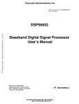
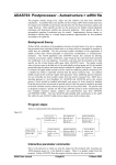
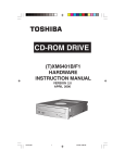
The following two figures show the timing diagrams and the values which must be programmed
into the RAM array. These values allow the UPM to generate the required timing for the Compact
Flash.
TRUE IDE
Read
Clk
T T T T
1 2 3 4
Address
thA(IORD)
CS0# & CS1#
IORD#(GPL1)
Data
tsuCE(IORD)
thCE(IORD)
tw(IORD)
tsuA(IORD)
tdfIOIS16(ADR)
td(IORD)
BIT
0
1
2
3
4
5
6
7
8
9
10
11
12
13
14
15
16
17
18
19
20
21
22
23
24
25
26
27
28
29
30
31
NAME
CST1
CST2
CST3
CST4
BST1
BST2
BST3
BST4
G0L
G0L
G0H
G0H
G1T1
G1T3
G2T1
G2T3
G3T1
G3T3
G4T1
G4T3
G5T1
G5T3
REDO
REDO
LOOP
EXEN
AMX
AMX
NA
UTA
TODT
LAST
RSS
1
1
0
0
0
0
0
0
1
1
1
1
1
1
1
1
1
1
1
1
1
1
0
0
0
0
0
0
0
0
0
0
RSS+1 RSS+2 RSS+3 REDO1 REDO2 REDO3 RSS+4 RSS+5 RSS+6
0
0
0
0
0
1
0
0
0
0
0
1
0
0
0
0
0
1
0
0
0
0
0
1
0
0
0
0
0
0
0
0
0
0
0
0
0
0
0
0
0
0
0
0
0
0
0
0
1
1
1
1
1
1
1
1
1
1
1
1
1
1
1
1
1
1
1
1
1
1
1
1
1
0
0
0
1
1
1
0
0
0
1
1
1
1
1
1
1
1
1
1
1
1
1
1
1
1
1
1
1
1
1
1
1
1
1
1
1
1
1
1
1
1
1
1
1
1
1
1
1
1
1
1
1
1
1
1
1
1
1
1
0
0
1
0
0
0
0
0
1
0
0
0
0
0
0
0
0
0
0
0
0
0
0
0
0
0
0
0
0
0
0
0
0
0
0
0
0
0
0
0
0
0
0
0
0
1
0
0
0
0
0
0
0
0
0
0
0
0
0
1
* MPC8260 PowerQUICC II User’s Manual 4/1999 Rev. 0, MPC8260 PowerQUICC II Users Manual Errata 8/2000 Rev. 1
12
TRUE IDE
Write
Clk T T T T
1 2 3 4
Address
tsuCE(IOWR)
CS0# & CS1#
IOWR#(GPL2)
thCE(IOWR)
tw(IOWR)
tsuA(IOWR))
Data
thA(IOWR)
th(IOWR)
tsu(IOWR)
BIT
0
1
2
3
4
5
6
7
8
9
10
11
12
13
14
15
16
17
18
19
20
21
22
23
24
25
26
27
28
29
30
31
NAME
CST1
CST2
CST3
CST4
BST1
BST2
BST3
BST4
G0L
G0L
G0H
G0H
G1T1
G1T3
G2T1
G2T3
G3T1
G3T3
G4T1
G4T3
G5T1
G5T3
REDO
REDO
LOOP
EXEN
AMX
AMX
NA
UTA
TODT
LAST
WSS
1
1
0
0
0
0
0
0
1
1
1
1
1
1
1
1
1
1
1
1
1
1
0
0
0
0
0
0
0
0
0
0
WSS+1 WSS+2 REDO1 REDO2 REDO3 WSS+3 WSS+4 WSS+5 WSS+6
0
0
0
0
0
0
0
0
0
0
0
0
0
0
0
0
0
1
0
0
0
0
0
1
0
0
0
0
0
0
0
0
0
0
0
0
0
0
0
0
0
0
0
0
0
0
0
0
1
1
1
1
1
1
1
1
1
1
1
1
1
1
1
1
1
1
1
1
1
1
1
1
1
1
1
1
1
1
1
1
1
1
1
1
1
0
0
0
1
1
1
0
0
0
1
1
1
1
1
1
1
1
1
1
1
1
1
1
1
1
1
1
1
1
1
1
1
1
1
1
1
1
1
1
1
1
1
1
1
1
1
1
0
1
1
1
0
0
0
1
0
0
0
0
0
0
0
0
0
0
0
0
0
0
0
0
0
0
0
0
0
0
0
0
0
0
0
0
0
0
0
0
0
0
0
0
0
0
1
0
0
0
0
0
0
0
0
0
0
0
0
1
* MPC8260 PowerQUICC II User’s Manual 4/1999 Rev. 0, MPC8260 PowerQUICC II Users Manual Errata 8/2000 Rev. 1
13
Program MxMR
The following contains the recommended values for MxMR as described in Table 10-9 from the
8260 User’s Manual( page 10-27)
MxMR: Table 10-9 Machine x Mode Registers , pg 10-27
Bits
Name
Value
Description
0
BSEL
0b0
Bus Select Assigns banks that select UPMx to the 60x or
local bus. 0b0=60x
2-3
1 RFEN
OP
0b0
0b00
Refresh enable. 0b0= Refresh services are not required
Command opcode. Determines command executed by
UPMx when a memory access hits a UPM assigned bank.
0b00= Normal operation
Reserved, should be cleared
Address multiplex size. See 10.6.4.2
Disable timer period
General line 0 control. GPL0 is not used
GPL_A4 output line disable. These lines are not use
Read loop field. Determines number of times a loop
defined in the UPMx will be executed for a burst or singlebeat read pattern or when MxMR[OP]=11; 0001= loop is
executed 1 time. Not used.
Write loop field. See RLFx. Not used
Refresh loop field. Doesn't matter.
Machine address. RAM address pointer for the command
executed. This field is incremented by 1, each time the
UPM is accessed and the OP field is set to WRITE or
READ. Set when programming RAM array.
4
5-7
8-9
10-12
13
14-17
AMX
DSx
G0CLx
GPL_x4DIS
RLFx
0b0
0b000
0b00
0b000
0b0
0b0001
18-21
22-25
26-31
WLFx
TLFx
MAD
0b0001
0b0001
0b000000
* MPC8260 PowerQUICC II User’s Manual 4/1999 Rev. 0, MPC8260 PowerQUICC II Users Manual Errata 8/2000 Rev. 1
14
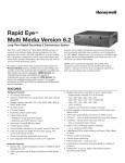
4.0 Schematic
VCC=3.3V
Power On Reset
RESET#
CS0#
CS0#
CS1#
CS1#
GPL1
IORD#
GPL2
IOWR#
A0-A2
A0-A2
A3-A10
GND
D0-D15
D0-D15
IRQ0#
INTRQ
GND
ATA SEL#
CSEL#
Vcc
8260
REG#
WE#
Compact Flash
* MPC8260 PowerQUICC II User’s Manual 4/1999 Rev. 0, MPC8260 PowerQUICC II Users Manual Errata 8/2000 Rev. 1
15
5.0 Software Notes
Although you could write your own IDE driver, most real time operating systems like VxWorksTM
already provide either an ATA or IDE driver. The IDE driver sends the appropriate ATA
commands to the CompactFlash. Ideally, no additional driver software needs to be written;
however it will be necessary to the base address from the primary IDE port (1F0h) to the value
associated with the chip select.
Software may want to take advantage of CompactFlash’s INTRQ (interrupt request) to notify the
8260 processor when the CompactFlash is ready. Alternatively, one can poll the busy bit of the
status register to determine when the CompactFlash is ready.
Please note: When programming the RAM array for the UPM, a single byte access is needed after
loading each RAM value into the UPM.
6.0 Conclusion
CompactFlash cards are a widely available solution for systems requiring a compact, solid state
mass storage system. Because they interpret standard ATA disk drive commands, little or no
software development is necessary because software drivers for ATA devices already exist for most
operating systems. The hardware interface for each system may need to be customized, but as
indicated in the example presented, the chipset may already possess the capability to interface
gluelessly to CompactFlash. If a PCMCIA controller is not present in the system, it will be easier to
interface using the True IDE mode (assuming hot insertion and removal is not a requirement).
7.0 References
7.1 Datasheets
THNCFxxxMAA Series Compact Flash Card datasheet 3/2001
MPC8260 PowerQUICC II User’s Manual 4/1999 Rev. 0
MPC8260 PowerQUICC II Users Manual Errata 8/2000 Rev. 1
7.2 Toshiba Website
www.toshiba.com/taec
7.3 Contact Information
Toshiba welcomes your feedback on this document. Please send any comments and ideas to
TAEC eSupport at:
[email protected].
* MPC8260 PowerQUICC II User’s Manual 4/1999 Rev. 0, MPC8260 PowerQUICC II Users Manual Errata 8/2000 Rev. 1
16