1
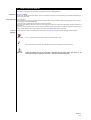
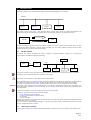
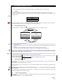
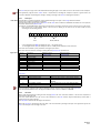
MODBUS
Serial Communication Protocol
User Manual
1
CONTENTS
1
2
3
Contents................................................................................................................................................................2
How to use this manual ....................................................................................................................................3
Introduction .........................................................................................................................................................4
4
3.1
3.2
Modbus Network............................................................................................................................................................................. 4
Other types of network .................................................................................................................................................................. 4
The Modbus standard protocol.......................................................................................................................6
4.1
Frames ............................................................................................................................................................................................... 6
4.2
The query-response cycle............................................................................................................................................................... 6
Serial transmission mode........................................................................................................................................................................... 6
4.3.1
4.4
5
4.4.1
4.4.2
4.4.3
4.4.4
8
9
Device Address .............................................................................................................................................................................................................................7
Function code ..............................................................................................................................................................................................................................7
Data bytes.....................................................................................................................................................................................................................................8
CRC field ........................................................................................................................................................................................................................................8
Error controls .......................................................................................................................................................9
5.1
5.2
Parity check ...................................................................................................................................................................................... 9
CRC check ......................................................................................................................................................................................... 9
5.3
Timeout ............................................................................................................................................................................................. 9
7.1
Functions and Examples..............................................................................................................................................................12
8.1
8.2
8.3
ASCII coding ...................................................................................................................................................................................17
RTU coding .....................................................................................................................................................................................17
ASCII framing .................................................................................................................................................................................17
5.2.1
6
7
Character serial transmission ..................................................................................................................................................................................................6
Creating frames with RTU coding ............................................................................................................................................... 7
CRC calculation algorithm.......................................................................................................................................................................................................9
Diagnostics........................................................................................................................................................ 11
Functions ........................................................................................................................................................... 12
Appendix............................................................................................................................................................ 17
Glossary.............................................................................................................................................................. 18
MODBUS
2/20
2
HOW TO USE THIS MANUAL
x
x
This manual is designed to permit quick, easy reference with the following features:
References
References column:
A column to the left of the text contains references to subjects discussed in the text to help you locate the information you
need quickly and easily.
Cross references
Cross references:
All words written in italics are referenced in the subject index to help you find the page containing details on this subject;
supposing you read the following text:
”when the alarm is triggered, the compressors will be shut down”
The italics mean that you will find a reference to the page on the topic of compressors listed under the item compressors
in the index.
If you are consulting the manual "on-line" (using a computer), words which appear in italics are hyperlinks: just click on a
word in italics with the mouse to go directly to the part of the manual that discusses this topic.
Icons for
emphasis:
Some segments of text are marked by icons appearing in the references column with the meanings specified below:
<IMG INFO>
36,75
Take note:
marks a specific note on the topic that the user should bear in mind
<IMG INFO>
28,3
29,3
0
2
Tip:
marks a tip that can help the user understand and use the information on the topic better.
Warning! :
marks information that if not thoroughly comprehended may badly affect the system or be
hazardous for people, equipment, data, etc..; users must read these warnings.
MODBUS
3/20
3
INTRODUCTION
x
x
The Modbus protocol is for communications between devices connected together over a network.
Network
Device 1
Device 2
Device n
Devices
The system is based on the master - slave mechanism where only the master device can initiate communications. The
other devices (slaves) respond either by supplying data or performing the operations requested by the master.
MASTER
slave
Generally speaking, the protocol describes the routines a device has to use to: request access to another device, respond
to queries from other controllers or devices, detect and signal errors and, lastly, establish a common format for both
content and layout in the various fields of the message.
3.1
Modbus Network
As regards the physical connection, the devices normally use RS232 compatible interfaces for point-to-point
communications or RS485 for multidrop connections.
MASTER
MASTER
RS232
Slave
RS485
Slave 1
Slave 2
Slave
Slave n
The type of connection, wiring, signal levels and communications parameters such as parity and baud rate are defined.
Controllers can be connected directly over a network or via modem.
Each device must be assigned a unique address for the entire network.
broadcast
During communications over a Modbus network the protocol establishes how each device recognises a message addressed
to it, determines the type of action to take, extracts the data and any other information contained in the message.
If a response is envisaged, the slave device, using the Modbus protocol, will in its turn create and send the message.
The protocol makes it possible to send messages either to a single slave, specifying the address in the query packet, or to
all the slaves on the network via a broadcast message. The slave responds to the master's queries only if individually called
upon (addressed).
Slaves do not respond to broadcast messages (broadcast/no response system).
In particular, the queries of the master device will comprise:
Device address (or broadcast address)
•
Function code that defines the required action
•
A set of data
•
An error check field.
•
Similarly, the responses of a slave device will contain the fields that confirm the actions performed, the data that need to
be returned and an error check field.
If an error occurs in communicating the message, or if the slave cannot perform the requested action, the slave will create
an error message and send it in response.
3.2
Other types of network
On other types of network, the messages containing the Modbus protocol are enclosed in the frames of the network used.
MODBUS
4/20
The controllers of the Modbus network, via the relevant software applications and drivers, will make the conversion
between the Modbus protocol and the specific protocol used by the network.
MODBUS
5/20
4
THE MODBUS STANDARD PROTOCOL
x
x
x
This section examines the technical and operating specifications of the Modbus protocol in greater detail.
4.1
Frames
Communication between two devices via the modbus protocol takes place with an exchange of frames (structure).
In a frame, composed of a set of bits, there is a start, an end and an internal structure that can be exemplified by the
following outline:
Frames
Device
Function
8 bits Data Byte
Error Check
The maximum length of a packet is closely tied to the transmission/reception buffer of the interface used. It is therefore a
function of the resources. In any case, a message can be at most 256 bytes long.
4.2
The query-response cycle
A communications cycle between a master and a slave device takes place by an exchange of frames:
QUERY Master
Device
Device
Function
Function
Eight bit – Data Bytes
Eight bit – Data Bytes
Error
Error
RESPONSE
Query
<IMG INFO>
28,3
29,3
1
Response
The query will contain the following fields:
Device address: address of the slave in the network. This address necessarily needs to be the same in both the query
•
and the response.
Function code: The function code in the query tells the slave device concerned (addressed) the type of action to
•
perform.
Data bytes: contain any additional information that the slave needs to perform the function.
•
Error check: The check error field provides a method to check the integrity of the message content
•
For example, the function with code 03 (decimal) requests the slave to read the registers (holding register) and to respond
with their values. The data field, in this example, will contain the data informing the slave from which register (variable) to
begin and for how many registers to continue reading
If the slave creates a normal response, the function code in the response is an echo of the query function code. The data
bytes field contains the data collected by the slave, such as the value of a register.
If an error occurs, the function code is modified to indicate that the response is an error-response and the data bytes field
contains a code describing the error.
The error check field enables the master to understand whether the message content is valid.
4.3
Serial transmission mode
The instruments can be configured to communicate with the Modbus network standard using two transmission codes:
ASCII and RTU.
They establish how the bits form the fields of the frame.
The type of coding used is pre-set by the firm or can be selected together with the communications parameters (parity,
baud rate, etc.).
The type of coding (ASCII/RTU), and relevant parameters (parity, baud rate) must be the same for all the devices
on the network.
The coding used by the Eliwell/Microtech devices is RTU; in the remainder of this manual we will therefore always either
explicitly or implicitly refer to this type of coding.
4.3.1
Character serial transmission
When messages are transmitted over a Modbus standard serial network, each character or byte is sent in this order (from
left to right):
Least Significant Bit (LSb) … … … Most Significant Bit (MSb).
MODBUS
6/20
With the RTU characters the sequence is as follows:
With parity check byte
Start
LSb
MSb
Parity
Without parity check byte
Start
LSb
MSb
Stop
4.4
Stop
Stop
Creating frames with RTU coding
A frame created with RTU coding has the following structure:
RTU framing
Start
Device Address
Function Code
Data Bytes
ErrorCheck-CRC
End
T1-T2-T3-T4
8 bit
8 bit
n x 8 bit
16 bit
T1-T2-T3-T4
In RTU coding, messages start with a silence lasting at least equal to the time for transmitting 3.5 characters.
Character-time
It is more common practice to use a multiple of the transmission time of a character (shown as T1-T2-T3-T4 in the figure.
Where T-nth = transmission time of 1 character).
<IMG INFO>
28,3
29,3
1
If the transmission speed is set to 9600 baud rate the transmission time of one character will be equal to (1/9600) * 8
(number of bits to make one character in RTU code) = 0.00083
4.4.1
Device Address
The address field of a message contains eight bits (RTU).
Valid addresses for slave devices lie in the range between 0 … and 255 (decimal values).
A master device addresses the message to a designated slave by putting the slave's address in the device address field of
the message. When a slave responds, it puts its own address in the address field so the master can identify it.
The address 0 is used for the Broadcast address, which identifies all the slaves. Slaves do not respond to a broadcast query.
In some Microtech/Eliwell instruments the address field is interpreted as two nibbles respectively specifying the family and
the device (address within the family);
example:
The address 11010011 is interpreted as
1101 → Family 11
•
0011 → Device 3
•
When the Modbus protocol is used on a higher level network (other types of network (e.g. on TCP-IP), the broadcast
service might not be permitted or it could be replaced by other methods.
The devices connected to the network constantly analyse the network bus, also during periods of silence.
When a device receives the first field (address field), it decodes it to find out whether the address it contains is its own, in
which case it goes on to read the rest of the message.
In sequence, straight after the last character transmitted, an interval of at least 3.5 character-time marks the end of the
message, after which a new message can commence.
The entire frame of the message has to be transmitted in a continuous stream.
If there is an interval longer than 1.5 character-time before completing the frame, the receiving device will delete the
incomplete message and consider the next byte received as the start of the address field of a fresh message. Likewise, if a
new message starts sooner than the interval of 3.5 character-time following a previous message, the receiving device will
consider it as a continuation of the former one. This would cause an error in the final value of the CRC, which would
establish that joining the two messages is not legitimate.
4.4.2
Function code
Function code
The function code field of a message contains eight bits (RTU). Valid codes lie in the range from 1 to 255 (decimal values).
Only a few functions of the modbus protocol are implemented in the Eliwell/Microtech controller.
When a message is sent from a master to a slave device, the function code field specifies the kind of action to take.
For example, read the ON/OFF status of a set of digital variables, read the data of a set of registers, write to a specific
register…..
When the slave responds to the master, it uses the function field to indicate either a normal response, if there are no
errors, or some kind of error that has occurred (exception response).
For a normal response, the slave simply repeats (echo) the original code. In the case of an exception response, the slave
returns a code that is equivalent to the original function code with the most significant bit (MSb) set to one (logic 1).
<IMG INFO>
28,3
29,3
1
For example, a message from the master to the slave to read a set of registers would have the following function code:
0000 0011
(hexadecimal 03)
If the slave receives the query and performs the envisaged action without error then it will return the same code in its
response.
If there is an exception the slave will return:
1000 0011
(hexadecimal 83)
MODBUS
7/20
The slave will put a single code in the data field describing the type of error that occurred or the reason for the exception.
The application program of the master device is responsible for handling the exception responses. Typical actions are
successive attempts at resending the message, sending a message to the slave or notifying the operators.
4.4.3
Data field
Data bytes
The data field is created using blocks of two hexadecimal figures (1 byte), in the range between 00 and FF.
These form a single RTU character of eight bits.
The data field of the message sent by the master to the slave device contains the additional information to use to perform
the action defined in the function code.
In particular, in Eliwell/Microtech devices the first two bytes are basically used to gain access to the resources of the slaves:
Each resource has a logic address where it can be seen to belong to an area and to an offset inside the area
•
according to the following outline:
BIT
15
BIT
0
Area
Offset (address)
5 most significant bits (MSb) to identify the area -> 32 possible areas
11 least significant bits (LSb) to identify the offset -> 2048 possible addresses inside each area.
•
•
The areas can be divided up into: parameters, analogue inputs, timer,...
Each area can be accessed for reading or writing with the function code specified here:
Logic areas
area no.
description
1
2
3
4
5
6
7
8
parameters
analogue inputs
timer
digital inputs
digital outputs
EEPROM
analogue outputs
RAM
Reading function
(function code)
3
4
3
2
1
3
3
3
Writing function
(function code)
16
-16
-15
16
16
16
That is
functions
function
1-2
3-4
function description
reading digital variable
reading analogue variable
15
16
writing digital variables
writing analogue variables
action
obtains the value of one or more digital variables
obtains the value of one or more analogue
variables
forces the value of one or more digital variables
forces the value of one or more analogue variables
Areas 6 and 8 are used when the limited availability of device resources does not permit using logic areas.
Then the specified address is the real (physical) address of the resource in RAM or in EEPROM.
4.4.4
CRC field
When using RTU transmission coding to form message frames, the error check field contains a 16 bit value composed of
two bytes (of eight bits each).
The error check characters are the result of the calculation of the CRC function (Cyclical Redundancy Check) that is
performed on the entire message.
The CRC field is added to the message as the last field.
When the CRC field is formed the low-order byte is set first, followed by the high-order byte. The high-order byte of the
CRC is the last byte in the message to be sent.
MODBUS
8/20
5
ERROR CONTROLS
x
x
The standard Modbus serial network uses three types of error check:
The parity check (odd/even) that can be applied, as an option, on each character forming the frame.
•
The frame check (CRC) on the other hand is applied to the entire message.
•
Timeout
•
5.1
parity
<IMG INFO>
28
29
1
Parity check
Users can configure devices to perform the Even or Odd Parity check or for a No Parity check. This will determine how the
parity bit is set for each character.
If Odd or Even Parity has been specified, the number of bits ON (1) will be counted in the data section of each character
(seven data bits for ASCII coding, eight for RTU coding). The parity bit will then be set to 0 or 1 if the total number of bits
equal to 1 is even or odd.
For instance, supposing that these eight bits form a character transmitted with RTU coding:
1100 0101
The total number of bits in the frame equal to 1 is four.
If Even Parity has been set, the frame parity will be equal to 0 since the total number of bits equal to 1 (including the
parity bit) is four, which is an even number.
Whereas if we use Odd Parity, the parity bit will be set to 1, thereby making the total an odd number (there are 5 bits
equal to 1).
When the message is transmitted, the parity bit is calculated and applied to each character in the frame. The receiving
device counts the number of bits equal to 1 and returns an error if this is not the same as the parity setting (all devices in
a Modbus network have to be configured to have the same parity check method).
<IMG INFO>
28
29
1
Notice that the parity check can only detect an error if there is an odd number of bits in error.
If, for instance, we have set the Odd Parity check and two 1 bits have been lost from a character containing three 1 bits,
the result will still be an odd number of bits equal to 1.
Lastly, if we have specified No-Parity, no check is made and a stop bit is added instead of the parity bit.
5.2
CRC
CRC check
In the RTU coding the messages include an error check field that is based on the CRC method.
The CRC field checks all the content of the entire message.
This check is applied irrespective of any parity method being used to verify the single characters of the message.
The CRC field comprises two bytes, containing a binary value of 16 bits. The CRC value is calculated by the transmitting
device, which adds it to the message.
The receiving device, when reading the message, recalculates the CRC and compares it with the value received in the CRC
field. If these two values are not the same there is an error.
5.2.1
CRC calculation algorithm
Passo n°1
Set a 16 bit variable with the hex value FFFF (equal to all 1 in the binary system). This variable is called
the "CRC register".
Passo n°2
Compare the first byte (of eight bits) of the message with the low-order byte of the CRC register using
the exclusive OR operator. Put the result in the CRC register.
Passo n°3
Shift the CRC register one bit to the right (towards the LSB), filling the MSB with 0. Take out the
content of the LSB and examine it.
Passo n°4
If the value of the LSB is zero, repeat Step no. 3. If the LSB is 1, compare the CRC register, using the
exclusive OR operator, with the hex (polynomial ?) value A001 (1010 0000 0000 0001).
Passo n°5
Repeat Step no.3 and no.4 until all eight shifts have been performed. Then, another byte will be
processed.
Passo n°6
Repeat Steps from no.2 to no.5 for the following bytes of the message. Continue until all the bytes have
been processed.
Result: The content of the CRC register is the required CRC value.
Passo n°7
When the CRC is put in the message, the higher and lower bytes need to have their positions swapped
over.
For example, if the CRC value is hex 1241 (0001 0010 0100 0001), the message will be:
Address
5.3
Function
code
Data count
Data
Data
Data
Data
CRC Lo (=41)
CRC Hi (=12)
Timeout
The master is generally configured by the user to wait for a set timeout interval before cancelling the communication
(transaction).
The interval is set sufficiently long so that all slave devices can respond normally.
If the slave detects a transmission error the message will not be taken into consideration and the slave not create a
response for the master. In this way the timeout will end and will permit the master program to handle the error.
MODBUS
9/20
For example, for the Energy 400 device the maximum length of time that can elapse between sending a packet from the
master and the slave's response is 4 ms.
A message addressed to a non-existent slave device will not create a timeout either.
Note:
(Other networks such as MAP or Modbus Plus use a frame check at a higher level than the Modbus content of the
message. On these networks, the CRC check field of the Modbus message is not applied. In the event of a transmission
error, the specific protocol of these networks will notify the originating device (of the message) (the master since the slave
will make no attempts whatsoever) that an error has occurred and will permit it to make another attempt or to cancel the
send depending on how it is set. If the message has been delivered, but the slave device cannot respond, there is an error
similar to a timeout that can be detected by the master's program.)
MODBUS
10/20
6
DIAGNOSTICS
x
x
x
Except for messages such as broadcasts, when a master device sends a query to a slave it waits for a response.
Any of the following 4 cases may occur:
If the slave receives the message without any errors, and it can handle the queries normally, it returns a "normal
•
response".
If the slave fails to receive the query due to a communications error, it gives no response.
•
If the slave receives the query, but it detects a communications error (parity, CRC …), it gives no response. The master
•
program will evaluate whether there is a timeout condition.
If the slave receives the query without any communications errors, but it is not able to handle it (for instance, if the
•
query is to read a register that does not exist), the slave will give an "exception response" informing the master of the
nature of the error.
The "exception response" has two fields that distinguish it from a "normal response": the function code field and the data
field
Function code
field:
Data field:
In a normal response, the slave repeats the master's query function code.
All function codes have 0 as their most significant bit (MSb) since their hexadecimal values are always lower than 80.
In an “exception response”, the slave sets the most significant bit (MSb) of the function code to 1. The master program may
acknowledge the “exception response” and then examine the data field to find the error code.
In a “normal response”, the slave returns the required information.
In an “exception response”, the slave returns the error code as specified in the following table:
Code
Name
01
Illegal function
02
Illegal data address
03
Illegal data address
ADD
01
COM
81
ERR
02
Meaning
CRC
CRC
The function code received in the query is not a possible action for the
slave.
The data address, in the data field, is not a valid address for the slave.
Area not corresponding to the function, index 0, index non-existent in the
requested area
The figure in the data field is not accessible for the slave. Too many data
requested for the area content, tx buffer exceeded in the response
CRC
CRC
RESPONSE WITH ERROR 02 TO FUNCTION 01
MODBUS
11/20
7
FUNCTIONS
x
x
This section provides some examples on using the functions implemented in Eliwell/Microtech devices.
The following table sums up the commands available in the various logic areas:
Function
code
(decimal)
1
Logic area
(decimal)
5
Digital outputs
4
Digital inputs
1
Parameters
6
EEPROM
7
Analogue outputs
8
RAM
4
2
Analogue inputs
15
5
Digital outputs
1
Parameters
6
EEPROM
7
Analogue outputs
8
RAM
2
3
16
7.1
Area Description
Function description
Type of action of the function
Reading digital variable
Obtains the values of one or more
digital variables
Reading analogue variables
Obtains the values of one or more
analogue variables
Writing digital variables
Forces the value of one or more
digital variables
Writing analogue variables
Forces the value of one or more
analogue variables
Functions and Examples
The examples refer to the function and area (they hold for any instrument implementing them).
Function code 01
(01 hex)
The function code 01 (01 hex) is used to read digital variables contained in the slave resources, which have digital outputs
(logic area dec).
The broadcast service is not implemented with this function
<IMG INFO>
28
29
1
Field
No. of bytes
Slave address
Function code
First bit address
Number of bits
CRC
1
1
2
2
2
Example: reading the digital output RL1 on the slave with address 1. The resource RL1 is indexed (that is it has its logic
address) on 1.
Query: 01 01 28 01 00 01
Response: 01 01 01 xx
Query (hex)
RTU 8-bit (binary)
Description
01
01
0000 0001
0000 0001
28 01
0010 1000 0000 0001
00 01
0000 0000 0000 0001
Address of the slave in the network
Function code
Hexadecimal value to indicate the logic area 5 and the index 1 of the
resource RL1
Hexadecimal value to indicate the consecutive number of variables to read
The hexadecimal value 28 01 has been obtained by applying the data field format for the logic area.
Taking the first 5 bits (00101) we get the decimal value 5, while the remaining 11 bits give us the logic address of the
variable to read (in this case it is 1). The following 2 bytes (00 01) specify the number of variables to read after the one
contained in the previous address (in the example at issue there is just one variable to read).
Response
(hex)
01
01
01
xx
RTU 8-bit (binary)
Description
0000 0001
0000 0001
0000 0001
xxxx xxxx xxxx xxxx
Address of the slave in the network
Function code (echo)
Hexadecimal value to indicate the index 1 of the resource RL1.
Values contained in the variables to read
MODBUS
12/20
Function code 02
(02 hex)
The function code 02 (02 hex) is used to read the digital variables contained in the resources of the slave, which have
digital inputs (logic area 4 dec).
The broadcast service is not implemented with this function
<IMG INFO>
28
29
1
Field
No. of bytes
Slave address
Function code
First bit address
Number of bits
CRC
1
1
2
2
2
Example: reading the digital inputs ID2 and ID3 on the slave with address 1. The resources ID2 and ID3 are indexed (their
logic address) on 2 and 3 respectively.
Query: 01 02 20 02 00 02
Response: 01 02 01 xx
Query (hex)
RTU 8-bit (binary)
Description
01
02
0000 0001
0000 0010
20 02
0010 0000 0000 0010
00 02
0000 0000 0000 0010
Address of the slave in the network
Function code
Hexadecimal value to indicate the logic area 4 and the index 2 of the
resource ID2
Hexadecimal value to indicate the number of consecutive variables to read
The hexadecimal value 20 01 has been obtained by applying the data field format for the logic area. Taking the first 5 bits
(00100) we have the decimal value 4, while the remaining bits give us the logic address of the variable to read (in this case
it is 2). The next 2 bytes (00 02) specify the number of variables to read after the one contained in the previous address (in
the example at issue there are two variables to read).
Response
(hex)
01
02
01
xx
Function code 03
(03 hex)
RTU 8-bit (binary)
Description
0000 0001
0000 0010
0000 0001
xxxx xxxx xxxx xxxx
Address of the slave in the network
Function code (echo)
No. of data bytes
Values contained in the variables to read
The function code 03 (03 hex) is used to read the analogue variables contained in the resources of the slave. The logic
areas to which the function refers are: Parameters, EEPROM, Analogue outputs, RAM.
The broadcast service is not implemented with this function
<IMG INFO>
28
29
1
Field
No. of bytes
Slave address
Function code
First word address
Number of words
CRC
1
1
2
2
2
Example: reading the vent. output 1 on the slave with address 1. The resource vent1 is indexed (its logic address) on 1.
Query: 01 03 38 01 00 01
Response: 01 03 02 00 xx
Query (hex)
RTU 8-bit (binary)
Description
01
03
0000 0001
0000 0011
38 01
0011 1000 0000 0001
00 01
0000 0000 0000 0001
Address of the slave in the network
Function code
Hexadecimal value to indicate the logic area 7 and the index 1 of the
resource vent. 1
Hexadecimal value to indicate the number of consecutive variables to read
The hexadecimal value 38 01 has been obtained by applying the data field format for the logic area. Taking the first 5 bits
(00111) we have the decimal value 7, while the remaining bits give us the logic address of the variable to read (in this case
it is 1). The following 2 bytes (00 01) specify the number of variables to read after the one contained in the previous
address (in the example at issue there is just one variable to read).
MODBUS
13/20
Response
(hex)
01
03
02
00
xx
Function code 04
(04 hex)
RTU 8-bit (binary)
Description
0000 0001
0000 0011
0000 0010
0000 0000
xxxx xxxx xxxx xxxx
Address of the slave in the network
Function code (echo)
No. of data bytes
If the area is a set of bytes this field is always on zero
Values contained in the variable to read
The function code 04 (04 hex) is used to read the analogue variables contained in the resources of the slave, which have
analogue inputs (logic area 2 dec).
The broadcast service is not implemented with this function
<IMG INFO>
28
29
1
Field
No. of bytes
Slave address
Function code
First word address
Number of words
CRC
1
1
2
2
2
Example: reading the analogue input ST1 on the slave with address 1. The resource ST1 is indexed (it logic address) on 1.
Query: 01 04 10 01 00 01
Response: 01 04 02 xx xx
Query (hex)
RTU 8-bit (binary)
Description
01
04
0000 0001
0000 0011
10 01
0001 0000 0000 0001
00 01
0000 0000 0000 0001
Address of the slave in the network
Function code
Hexadecimal value to indicate the logic area 7 and the index 1 of the
resource vent1
Hexadecimal value to indicate the number of consecutive variables to read
The hexadecimal value 10 01 has been obtained by applying the data field format for the logic area. Taking the first 5 bits
(00010) we get the decimal value 2, while the remaining bits give us the logic address of the variable to read (in this case it
is 1). The following 2 bytes (00 01) specify the number of variables to read after the one contained in the previous address
(in the example at issue there is just one variable to read).
Response
(hex)
01
04
02
xx
xx
Function code 15
(0F hex)
RTU 8-bit (binary)
Description
0000 0001
0000 0011
0000 0010
xxxx xxxx xxxx xxxx
xxxx xxxx xxxx xxxx
Address of the slave in the network
Function code (echo)
No. of data bytes
Values contained in the variable to read
Values contained in the variable to read
The function code 15 (0F hex) is used for writing the digital variables contained in the resources of the slave, which have
digital inputs (logic area 2 dec).
The broadcast service is implemented with this function
Field
No. of bytes
Slave address
Function code
First bit address
Number of bits
Byte count
Force data
CRC
1
1
2
2
1
n
2
The Byte count field indicates the number of bytes (8 bits) contained in the Data field.
The Force data field specifies the values to enter in the variables indicated.
<IMG INFO>
28
29
1
Example: writing the value ON (01 hex) in the digital output RL1 on the slave with address 1. The resource RL1 is indexed
(its logic address) on 1.
Query: 01 0F 28 01 00 01 01 01
Response: 01 0F 28 01 00 01
MODBUS
14/20
Query (hex)
RTU 8-bit (binary)
Description
01
0F
0000 0001
0000 1111
Address of the slave in the network
Function code
Hexadecimal value to indicate the logic area 5 and the index 1 of the
resource RL1
Hexadecimal value to indicate the number of variables to write
No. of data bytes
Value ON
28 01
0010 1000 0000 0001
00 01
01
01
0000 0000 0000 0001
0000 0001
0000 0001
The hexadecimal value 28 01 has been obtained by applying the data field format for the logic area. Taking the first 5 bits
(00101) we get the decimal value 5, while the remaining bits give us the logic address of the variable to write (in this case
it is 1). The following 2 bytes (00 01) indicate the number of variables to write after the one in the previous address (in the
example at issue there is just one variable to write).
In the Force data field the values to write in the variables are grouped 8 bits at a time and are represented by a
hexadecimal value. For example, if we have values type (ON-ON-OFF-OFF-ON-ON-OFF-ON), they correspond to the binary
value (1100 1101), that is the hexadecimal value CD hex.
Response
(hex)
01
0F
RTU 8-bit (binary)
Description
0000 0001
0000 0011
28 01
0000 0010
Address of the slave in the network
Function code (echo)
Hexadecimal value to indicate the logic area 5 and the index 1 of the
resource RL1
No. data written (corresponds to the no. of data requested)
00 01
Function code 16
(10 hex)
The function code 16 (10 hex) is used to write the analogue variables contained in the resources of the slave. The logic
areas to which the function refers are: Parameters, EEPROM, Analogue outputs, RAM.
The broadcast service is implemented with this function
Field
No. of bytes
Slave address
Function code
First bit address
Number of bits
Byte count
Force data
CRC
1
1
2
2
1
n
2
The Byte count field indicates the number of bytes (8 bits) contained in the Data field …..
The Force data field specifies the values to enter in the variables indicated.
<IMG INFO>
28
29
1
Example: writing the value xx in the analogue output vent. 1 on the slave with address 1. The resource vent. 1 is indexed
(its logic address) on 1.
Query: 01 10 38 01 00 01 02 00 xx
Response: 01 10 38 01 00 01
Query (hex)
RTU 8-bit (binary)
Description
01
10
0000 0001
0000 1111
Address of the slave in the network
Function code
Hexadecimal value to indicate the logic area 7 and the index 1 of the
resource vent. 1
Hexadecimal value to indicate the number of variables to write
No. of data bytes
If the area is a set of bytes this field is always on zero
Value to write
38 01
0011 1000 0000 0001
00 01
02
00
xx
0000 0000 0000 0001
0000 0010
0000 0000
Xxxx xxxx
The hexadecimal value 38 01 has been obtained by applying the data field format for the logic area. Taking the first 5 bits
(00111) we get the decimal value 7, while the remaining bits give us the logic address of the variable to write (in this case
it is 1). The following 2 bytes (00 01) indicate the number of variables to write after the one in the previous address (in the
example at issue there is just one variable to write).
Response
(hex)
01
10
RTU 8-bit (binary)
Description
0000 0001
0000 0011
38 01
0000 0010
Address of the slave in the network
Function code (echo)
Hexadecimal value to indicate the logic area 7 and the index 1 of the
resource vent. 1
MODBUS
15/20
00 01
No. data written
MODBUS
16/20
8
APPENDIX
x
x
8.1
ASCII
ASCII coding
When the controllers are set up for working in a Modbus network that uses ASCII coding (American Standard Code for
Information Interchange), each byte (eight bits) (2 hexadecimal characters) represents an alphanumeric character.
The greatest advantage of this coding is that it allows a time interval between two characters of up to one second (1 s)
without an error being signalled.
Each character is sent with 10 bits used as described here:
•
•
•
•
start bit
7 data bits, LSb (least significant bit) sent first
bit for odd/even parity – no bit for no parity
stop bit if parity is used or 2 stop bits for no parity
For example: coding the decimal figure 63 requires
start bit
7 data bits
1
0110110 (the ASCII code for 6)
1
0110011 (the ASCII code for 3)
8.2
RTU
2 characters (6 and 3) and therefore 2 transmissions:
2 stop bits (if no parity)
11
11
RTU coding
When the controllers are set up for communicating over a Modbus network that uses RTU coding (Remote Terminal Unit),
each byte (eight bits) represents two hexadecimal characters (4 bits each).
The greatest advantage in using this coding consists of the higher density of characters; it permits more efficient (faster)
transmissions than ASCII for the same baud rate.
Each character is sent with 10 bits used as described here:
•
•
•
•
start bit
8 data bits, LSB (least significant bit) sent first
bit for odd/even parity – no bit for no parity
1 stop bit if parity is used – 2 stop bits for no parity
For example: coding the decimal figure 63 requires 2 hexadecimal characters (6 and 3) that converted into binary format
are 0110 (6) and 0011 (3).
They are joined together to form a single byte so there is just one transmission:
start bit
8 data bits
2 stop bits (if no parity)
1
011000011 (the ASCII code for 6)
11
8.3
ASCII framing
If you use ASCII coding, the frames (messages) start with a colon ( : ) (ASCII 3A hex) and end with “carriage return” +
“line feed” or CRLF (ASCII 0D hex and 0A hex).
In transmitting all the other fields of the message the hexadecimal characters are used: 0 … 9, A … F.
The devices connected together in the network are constantly analysing the network bus, waiting for the colon ( : ). When
they receive this character, each device decodes the next field (address field) to find out whether its address is the one
specified.
There can be time intervals of up to one second between the characters in the message. If there is a longer time interval
between characters, the receiving device assumes that some kind of error has occurred during the transmission.
MODBUS
17/20
9
GLOSSARY
x
x
Logical OR
Exclusive OR
Stand by
Reset
Range
Multiple inputs with an OR relationship to one another are equivalent to a single input with the following status:
Active if at least one input is active
Inactive if no input is active
Two inputs related to one another are equivalent to a single input with the following status:
Inactive if both inputs are active or both are inactive
Active if only one of the two is active
Indicates that the instrument is waiting, in stand-by mode; all functions are suspended
Means set to zero.
Values falling within a given interval; Range 1...100 indicates all values between 1 and 100
Master
In communications between two devices, the term Master specifies the device that starts, governs and ends the
communication
Slave
In communications between two devices, the term Slave specifies the device that responds to and obeys the requests of
the Master
Baud rate
The baud rate (Baud) measures the transmission speed of a channel: 1Baud rate = 1 bit/1s
LSb
Least significant bit.
MSb
Most significant bit.
BUS
Type of physical connection between devices. All the devices are connected to the same physical line.
Timeout interval
Nibble
Timeout is the time limit on waiting to receive a message, after which an error is considered to have occurred
A nibble is a set of 4 bits (e.g. 1001)
MODBUS
18/20
MODBUS
19/20
10 ANALITIC INDEX
A
APPENDIX......................................................................... 17
ASCII coding..................................................................... 17
ASCII framing .................................................................. 17
B
Baud rate..........................................................................18
broadcast ........................................................................... 4
BUS.....................................................................................18
C
Character serial transmission ........................................ 7
CRC ...................................................................................... 9
CRC calculation algorithm............................................. 9
CRC check........................................................................... 9
CRC field ............................................................................. 8
Creating frames with RTU coding................................. 7
Cross references................................................................. 3
D
Data bytes .......................................................................... 8
Data field:.........................................................................11
Device Address .................................................................. 7
DIAGNOSTICS.................................................................. 11
E
ERROR CONTROLS............................................................ 9
Exclusive OR .....................................................................18
F
Frames................................................................................. 6
Function code.................................................................... 7
Function code 01 (01 hex)............................................12
Function code 02 (02 hex)............................................13
Function code 03 (03 hex)............................................13
Function code 04 (04 hex)............................................14
Function code 15 (0F hex) ............................................14
Function code 16 (10 hex)............................................15
Function code field:........................................................11
FUNCTIONS...................................................................... 12
Functions and Examples ............................................... 12
G
GLOSSARY.........................................................................18
H
HOW TO USE THIS MANUAL..........................................3
I
Icons for emphasis: ...........................................................3
INTRODUCTION ................................................................4
L
Logic areas..........................................................................8
Logical OR........................................................................ 18
LSb ..................................................................................... 18
M
Master............................................................................... 18
Modbus Network...............................................................4
MSb ................................................................................... 18
N
Nibble ............................................................................... 18
O
Other types of network ....................................................5
P
Parity check ........................................................................9
Q
Query ...................................................................................6
R
Range................................................................................ 18
References ...........................................................................3
Reset.................................................................................. 18
Response .............................................................................6
RTU coding .......................................................................17
RTU framing .......................................................................7
S
Serial transmission mode ................................................6
Slave.................................................................................. 18
Stand by ........................................................................... 18
T
THE MODBUS STANDARD PROTOCOL........................6
The query-response cycle ................................................6
Timeout ...............................................................................9
Timeout interval............................................................. 18
MODBUS
2000/09
MODBUS
Cod:
8MA10016
20/20