1
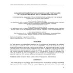
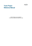
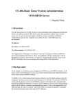
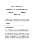
International Journal of Computer Applications (0975 – 8887) Volume 65– No.7, March 2013 Handheld Device to Control Intelligent Lighting System Ramandeep Singh Vaibhav Makharia Vaibhav Singhal Assistant Professor ITM University, Gurgaon ECE Department ITM University, Gurgaon ECE Department ITM University, Gurgaon The ARM7TDMI-S is a general purpose 32-bit microprocessor, which offers high performance and very low power consumption[5][2]. ABSTRACT With the rise in technology, one can accomplish things at a much faster rate and with a touch of a single button. Handheld aims at empowering a single user to control various LED panels that have been installed on various floors in various rooms of an educational institution. Handheld basically controls and receives information from an intelligent lighting system incorporating a graphic user interface and the touch control technology. Not only is it convenient to use but also saves electricity[10]. The ARM controller has been connected to a Graphic LCD along with a keypad matrix (refer figure 1) which constitutes the handheld device. ARM has been chosen because of abundant external interface resources[3]. The data gets transferred from ARM to GLCD parallel buses[9]. The data that is being transferred from the handheld device to the main computer (server) gets transferred serially and SerialMon (Data Monitor) software is being used for simulation purpose which has already been installed on the main server. KEYWORDS: ARM7 microcontroller (LPC2148), Graphical LCD (JHD12864E), Intelligent Lighting System, LED panels. From keypad matrix 3 switches are being, out of these 3, 2 switches have been used for going forward and backward or incrementing and decrementing any values. The third switch basically is being used for performing Enter/Go operation. The server would further control the various panels installed in various rooms in various floors. GENERAL TERMS: Interfacing of GLCD with ARM7 controller, Lighting systems, Central control, Packet design for serial communication. 1. INTRODUCTION Handheld devices are very popular in various fields for its features of easy carrying and flexibility. A few years ago, using black-and-white LCD for handheld device display was luxury, but now TFT true color display is widely used in handset device in accompany with the development of technology[8]. In this paper use of a handheld device to control an embedded intelligent lighting system would be discussed. All the connections as well as the features have been explained. This paper explains the basic block diagram along with its connections with the micro-controller. The main objective of the paper is to discuss this handheld device and explore future possibilities into exploiting this device. Also it is not always necessary to have lights at full intensity hence, the intensity can also be controlled using this device[11]. Graphical LCD is used to display floors and rooms in a building having panels installed. After selection of panel, action to be taken is shown on the page and now user is required to select one. Programming of LPC2148 will be done using a Serial interface which is a USB to RS232 convertor, as ARM header board has RS232 interface because of IBM PC standards[5][2] therefore for programming purposes, it has to be used to connect it to computer. Power supply unit is a 5 volt D.C. supply via an adaptor to GLCD and ARM board [2][6]. 2. BLOCK DIAGRAM OF HANDHELD 3. ARCHITECTURE OF GRAPHIC LCD (128x64) The 128x64 GLCD is divided into two equal halves with each half being controlled by a separate KS0108 controller[6]. Such GLCDs (using KS0108 controller) involve paging scheme, i.e., whole GLCD is divided equally into pages. The paging scheme of the graphical GLCD can be easily understood from figure 2. I. 128x64 GLCD implies 128 columns and 64 rows. In total there are (128x64 = 1024) pixels. Figure 1: Block Diagram 39 International Journal of Computer Applications (0975 – 8887) Volume 65– No.7, March 2013 II. 128x64 LCD is divided equally into two halves. Each half is controlled by a separate controller and consists of 8 pages. In figure 2, CS stands for Controller Select. III. Each page consists of 8 rows and 64 columns. So two horizontal pages make 128 (64x2) columns and 8 vertical pages make 64 rows (8x8). Let’s assume that a single pixel on top left of the graphic LCD needs to be glowed. For this the row would be set along with the column which will calculate the starting address (reference from GLCD manual). After making CS1 at logic high and giving as “00000001” using the data bus, a single pixel will glow on the display. Contrast Adjustment: The 2nd pin potentiometer is connected to the Vo pin of the GLCD (refer figure 3). This pin is responsible for the adjustment of contrast of the GLCD. In order to achieve sharpest contrast, this pin is given a logic high. Register Select: The pin P0.7 of the µC has been connected to the RS pin of the GLCD (refer figure 3 and figure 4). This pin is kept high to display data and low for instruction code. Read/Write: The pin P0.6 of the µC has been connected to the R/W pin of the GLCD (refer figure 3 and figure 4). This pin is kept low to write to the register of the GLCD while it is kept high to read from the register of the GLCD. Enable: The pin P0.5 of the µC has been connected to the EN pin of the GLCD (refer figure 3 and figure 4). When this pin is kept high it reads data while it writes data at high to low transition (falling edge). Reset: The pin P0.2 of the µC has been connected to the RST pin of the GLCD (refer figure 3 and figure 4). When this pin is applied with a high signal the µC gets resets and again starts from beginning position. Figure 2: Paging Scheme Figure 3: GLCD Pin Diagram 4. PIN CONSIDERATION In this project the Port 0 of LPC2148 (hereby “µC’’) for all the required Graphic LCD (GLCD) connections has been used. The pins used along with their functions are: Data Lines: The pins P1.0 to P1.7 of the µC have been assigned as data pins and have been connected to the DB0 to DB7 pins of the GLCD (refer figure 3) and are used to transfer data from the µC to the GLCD. Controller Select: The pins P0.0 and P0.1 of the µC are connected to the CS1 and CS2 pins of the GLCD (refer figure 3). The various combinations of these two pins would result in the desired page selection. Figure 4: Basic Interfacing of GLCD LCD Driving Voltage: Vee pin of the GLCD is connected to pin 1 of 10K potentiometer (refer figure 4). This is the output voltage that would drive the GLCD. 40 International Journal of Computer Applications (0975 – 8887) Volume 65– No.7, March 2013 Backlight Controls: LED+ and LED- pins of the GLCD (refer figure 4) are connected to Vcc and Gnd respectively.This will control the backlight of GLCD. 5. PAGE FORMATION FOR EMBEDDED USER INTERFACE The project here consists of pages with different information displayed on them. The letters on the GLCD have been displayed via glowing different combination of pixels[7]. Some of the pages are as follows:- 5.1 Page 1: Floor Screen Figure 6: Room Screen The top most box displays a welcome message along with the name of the handheld device. This page displays the number of floors (3 floors here) and a box at the bottom asks the user to choose the desired floor (refer figure 5). F1, F2 and F3 are the names used for Floor 1, Floor 2 and Floor 3 respectively. The black border around F1 indicates that floor 1 has been selected. 5.3 Page 3: LED Panel Screen This page contains information about how many LED panels are there in a room. The top most columns display the exact path of the panel i.e. (floor and room information). The bottom most box asks the user to select its desired panel. P1, P2 and P3 are the names used for LED Panel 1, Panel 2 and Panel 3 respectively (refer figure 7). The black border around P1 indicates that panel 1 has been selected. F1:R1 represents the floor and the room combination that is room 1 on floor 1. Figure 5: Floor Screen 5.2 Page 2: Room Screen The top most box would display the floor number that has been selected. This page displays the total number of rooms available on this floor (3 rooms here). A box at the bottom again asks the user to select the desired room (refer figure 6). R1, R2 and R3 are the names used for Room 1, Room 2 and Room 3 respectively. The black border around R1 indicates that Room 1 has been selected. Figure 7: Panel Screen 5.4 Page 4: Command Screen This page shows the commands to control the selected LED panel. The complete path (location) of the panel would be displayed in a box at the top (refer figure 8). The user can check or change the status, set the timer or intensity, or totally disconnect the entire system as per his need. There are three commands which have been described. The user can choose whichever command is desired. F1:R1:P1 represents floor that has been selected, the room on that floor and the panel in that room that has been selected. 41 International Journal of Computer Applications (0975 – 8887) Volume 65– No.7, March 2013 6. PACKET FORMAT DESIGNING In order for computer and controller to communicate, various methods like DMX over IP, serial communication, Art-Net, and the ACN (Architecture for Control Networks)[1] are available out of which serial communication by sending the respective bytes is being used. 6.1 COMMAND SELECTION BYTE AND PANEL This byte is mainly responsible for the commands that are provided to the GLCD via the µC. Figure 8: Command Screen 5.5 Page 5: Command Screen CS1 MSB This page shows two commands which gives the option to check the status or “on” and “off” the selected panel. CS0 F1 F0 R1 Floor bits: These two bits F0 and F1 are used to select a floor between the three floors available in the building where the panel is installed. F0 Room bits: These two bits R0 and R1 are used to select a room between the three rooms available in the previously selected floor where the panel is installed. R1 Figure 9: Command Screen R0 Panel bits: These two bits P0 and P1 are used to select the required panel between the three panels available in the selected room on which the given action needs to be performed. 5.6 Page 6: Status Screen This page would tell the user the current status of the LED panel that has been selected. The complete path (location) of the panel would be displayed in a box at the top (refer figure 10). P0 LSB CS0 F1 P1 Command bits: Two bits CS0 and CS1 refer to the command given to the server, stating what has to be done with the selected panel. CS1 R0 P1 F1/R1/P1 0 0 1 1 P0 F0/R0/P0 0 1 0 1 FUNCTION Floor/Room/Panel=0 Floor/Room/Panel=1 Floor/Room/Panel=2 No action 6.2 ACTION BYTE This byte is the 2nd byte which would be sent after the first byte has been received by the server and processed. A1 A0 T5 T4 T3 MSB Figure 10: Command Screen T2 T1 T0 LSB Action bits: Two bits A0 and A1 are used to communicate to the server what action needs to be performed on the selected panel. A1 A0 42 International Journal of Computer Applications (0975 – 8887) Volume 65– No.7, March 2013 Timer/Intensity bits: These six bits T0, T1, T2, T3, T4 and T5 have been used for setting the timer or controlling the intensity of Panel. T5 T4 T3 T2 T1 T0 6.3 FUNCTIONS OF COMMAND AND ACTION BYTE CS0 0 0 0 1 1 0 1 1 F1 F0 R1 R0 P1 P0 FUNCTION Check status/on or off Set the timer/Intensity change ADDRESS OF FLOOR/ROOM/PANEL FD* Total Disconnect Figure 11: Command Combinations Through some of the following sample codes it can be demonstrated how some of the commands are sent in two packets (packet-1 and packet-2) and analysed by the central server. 7.1 EXAMPLE 1 1st BYTE CS1 7. SAMPLE PACKETS AND ANALYSIS CS1 0 CS0 0 F1 0 F0 1 R1 1 R0 0 P1 1 P0 0 In this packet CS1 and CS0 are 0 which means that the status is being checked or the operation of switching on/off of the panel is being performed. F1 is 0 and F0 is 1 which states that the panel is on 1 st floor of the building. R1 is 1 and R0 is 0 states that the panel is in Room no 2 P1 is 1 and P0 is 0 states that we are accessing Panel no 2 A1 0 When CS0=0 AND CS1=0 PACKET-1 PACKET-2 A0 1 T5 - T4 - T3 - T2 - T1 - T0 1 2nd BYTE can be A1 0 A0 T5 T4 T3 T2 T1 0 - - - - - T0 FUNCTION - Check status 0:off 1:on On or off 0 1 1 0 FD* 1 1 FD* Figure 12: Action When CS0=0 AND CS1=1 A0 0 1 0 1 T5 T4 T3 T2 T1 Timer Value Intensity Value T0 FUNCTION Set Timer Set Intensity FD* FD* Figure 13: Action 7.2 EXAMPLE 2 CS1 0 2nd BYTE can be A1 0 0 1 1 In this packet A1 is 0, A0 is 1 and T0 is 1 which means panel is being switched on. 2nd BYTE can be A1 A0 T5 T4 T3 T2 T1 T0 0 0 - - - - - - 0 1 1 1 0 1 FUNCTION Total Disconnect FD* FD* FD* CS0 1 F1 0 F0 1 R1 1 R0 0 P1 1 P0 1 In this packet CS1 is 0 and CS0 is 1 which means Timer or Intensity is being set. F1 is 0 and F0 is 1 which states that the panel is on 1 st floor of the building. R1 is 1 and R0 is 0 states that the panel is in Room no 2 P1 is 1 and P0 is 1, states that we are accessing Panel no 3 When CS0=1 AND CS1=1 PACKET-1 PACKET-2 A1 A0 T5 T4 T3 T2 T1 T0 0 0 0 1 1 0 1 1 In this packet A1 and A0 are 0 which means Timer is being set. “011011”= 27 equivalent timer value will be loaded to the Timer of microcontroller. 8. FUNCTION DEFINATION Figure 14: Action FD* have been kept for future development i.e. to introduce some more functions in the existing setup. This section explains various function declarations which we are using as part of our research work in the handheld device. Following are the function declaration 43 International Journal of Computer Applications (0975 – 8887) Volume 65– No.7, March 2013 void ctrloff( ) void displayon( ) void displayoff( ) void setcolumn(unsigned char y) void setpage(unsigned char x) void setstartline(unsigned char z) void clrlcd( ) 8.1 CONTROL FUNCTIONS void ctrloff ( ) This function is used to provide a low signal to all the control pins i.e. Register select (RS), Read/Write (RW), Enable (EN), Controller Select (CS1,CS2). displayed on graphical LCD. So as a keyboard passes ASCII values to the computer similarly user needs to pass some special codes to display characters. Through *value, the data at the first address of that character is passed which has to be displayed on GLCD. 8.2.2 void lcdputs (unsigned char y, unsigned char x, unsigned char *str) In graphical LCD a single character is made by combination of different hex values given to each column of each page. Through this function those combinations are being passed. The value of x is the page on which the data has to be passed and y is the column from where we have to start line of the data to be displayed. 9. SNAPSHOT OF HANDHELD 9.1 PROJECT void displayon ( ) This function is used to glow the LCD’s backlight without affecting the internal status and displays ram data. void displayoff ( ) This function is used to “off” the LCD display backlight without affecting the internal status and display ram data. void setcolumn (unsigned char y) Function is used to select the column to which data has to be written in the LCD screen from the total of 128 columns in 128x64 graphical LCD. Figure 15: Snapshot of Handheld void setpage (unsigned char x) Function is used to select the page to which data has to be given from the total of 8 pages in 128x64 graphical LCD screen. void setstartline (unsigned char z) This function is used to set the start line from the column where we need to start the first letter of the string. This function is generally used to scroll the string on the graphical LCD. void clrlcd ( ) This function is used to delete the data contained in the LCD ram which is same as shown on the LCD screen. 8.2 DATA FUNCTIONS 8.2.1 void lcddata (unsigned char *value, unsigned int limit) This function is used to pass the value of the character which needs to display on the GLCD as it is a combination of many pixels together and it can be decided which pixel has to be Figure 16: Snapshot of page formation The above figure shows an ARM7 microcontroller, a Graphical LCD, a USB to serial convertor and power supply. 10. COMPARISON WITH CURRENT TECHNOLOGY One can easily argue about the installation of such complex system when the same can be achieved by a normal household switch. But the advantage handheld provides is the ease of controlling several panels while being present at a certain place. The user simply needs to pass the required command from the handheld which can be read by the server which would perform the desired action. 44 International Journal of Computer Applications (0975 – 8887) Volume 65– No.7, March 2013 Not only does it provide mobility, it can also be used for fault detection in the various LED panels. Also in an age where conservation of energy is an important aspect, Handheld comes as a true innovation aimed at saving energy. 11. RESULT Finally, a handheld device has been developed that would control an interior LED lighting system. Command packets are designed in 8 bit format which will be send from the handheld for controlling and analysis applications. These packet formats can be analysed using serial monitoring software. With the help of command packets handheld device can perform various operations viz status check, status toggle, timer setting, intensity level and disconnect. With the help of this device panel selection from different rooms on different floors in a building can be done just by sending panel selection command. With this design, a universal handheld device has been developed which can perform various controlling operations on interior LED lighting system remotely. 12. REFERENCES [1] Youjin Kim, Insu Kim, Tae-gyu Kang, Seong-hee Park “Analysis of IP-based Control Networks for LED Lighting Fixture Communication.”; New Trends in Information Science and Service Science (NISS);May 2010; 307-312 [2] Domingo, Azucena, N.Castro; Herber, T.J; Pajarillo, B; Visaya; Ballesil; Reyes, J.A; Hizon, J.R, “High-Level Implementation of an ARM7 Microprocessor with Multicore Capabilities”; TENCON 2007 - 2007 IEEE Region 10 Conference,Oct. 2007,1-4 [3] Zhu Zhao-you,Dai Sheng-hui; “Embedded LED Lighting Control System Research and Implementation.”; Computer Science and Information Technology; Aug 2009; 553-557 [4] Toshiaki Fujii, Fumlo Takeuchi, Hisao Yamada,Kazuo Kawasaki, Akira Saitoh, Tsuneyo Sumita; “DOT MATRIX LCD MODULE FOR GRAPHIC DISPLAY” (64 x 320 dots) IEEE Transactions on Consumer Electronics, Vol. CE-28, No. 3, Aug 1982; 196-201 [5] LPC214X user manual by NXP (founded by Philips). [6] Graphics LCD JHD12864E Datasheet. [7] Hua Zhou , Yang Liu, Dimitar Antonov Kolev, Jingjing Chen, Zonghe Lai and Johan Liu; “Design for Embedded Chinese Display Smart Card” High Density Microsystem Design and Packaging and Component Failure Analysis; Jun 2006; 152-156 [8] Li,Minglei Chen,Guiying Shang,xiaodong Mao,huabin, “Design of LCD Display System for Handheld Devices Based on Linux”; Electronics, Communications and Control (ICECC), Sept. 2011, 822 – 825 [9] Chandrashekhar Ghule, Dr. D.G. Wakde, Gurjinder Virdi, Neeta R. Khodke “Design of Portable ARM Processor based ECG Module for 12 lead ECG Data Acquisition and Analysis” Biomedical and Pharmaceutical Engineering, Dec 2009. 1-8 [10] Carmine Landi, Pietro Merola, Giacomo Ianniello, “ARM-Based Energy Management System using Smart Meter and Web Server”; Instrumentation and Measurement Technology Conference (I2MTC); 2011; 1-5 [11] T.P.Huynh, Y.K.Tan, K.J.Tseng; “Energy-Aware wireless Sensor Network with Ambient Intelligence for Smart LED Lighting System Control”; IECON 2011 37th Annual Conference on IEEE Industrial Electronics Society.; Nov 2011; 2923-2928 45