1
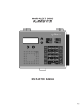
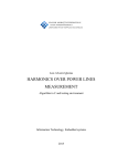
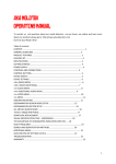
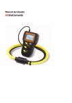
Rev. Page - GestureR User Manual - V1.0 1/32 GestureR User Manual June 5, 2014 2014/06/05 Copyright 2014 © Grabo Ideas. All rights reserved. [email protected] - GestureR User Manual - Rev. Page V1.0 2/32 Table of Contents 1. 2. 3. 4. Introduction...................................................................................................................... 6 Variants of GestureR ....................................................................................................... 6 2.1. GestureR SHIELD ................................................................................................. 6 2.2. GestureR SHIELD ULTRA..................................................................................... 7 2.3. GestureR BREAD .................................................................................................. 9 2.4. GestureR TINY .................................................................................................... 10 Arduino Sample Functions ............................................................................................ 11 Using Sensor Directly With I2C ..................................................................................... 11 4.1. Gesture and Proximity Sensing (GS) Part ........................................................... 11 4.1.1. I2C Slave Address for GS ......................................................................... 11 4.1.1.1. Write Format .............................................................................................. 12 4.1.1.2. Read Format .............................................................................................. 12 4.1.2. 4.1.3. 4.1.4. Basic Operation for Gesture Sensor and Proximity Sensor Mode ............ 13 Register Mapping ...................................................................................... 14 Register Functions .................................................................................... 15 4.1.5. Register Settings for Gesture and Proximity Sensing ............................... 15 4.1.5.1. GS Detection Result: .................................................................................. 15 4.1.5.2. Output Value of Sensing Result for Detection/non-detection ...................... 16 4.1.5.3. Output Value of Interrupt Result ................................................................. 16 4.1.5.4. Number of Measurement Cycles Setting .................................................... 17 4.1.5.5. Resolution/Measuring Duration Setting ...................................................... 17 4.1.5.6. Maximum Measurable Range..................................................................... 17 4.1.5.7. LED Drive Peak Current Setting ................................................................. 18 4.1.5.8. LED Pulse Setting ...................................................................................... 19 4.1.5.9. LED Pulse Width Setting ............................................................................ 19 4.1.5.10. Gesture and Proximity Low Threshold (Loff) .............................................. 19 4.1.5.11. Gesture and Proximity High Threshold (Lon).............................................. 20 4.1.5.12. Gesture Offset (Offset) ............................................................................... 20 4.1.6. 2014/06/05 Register Setting for Basic Operation ......................................................... 20 4.1.6.1. Software-Shutdown .................................................................................... 20 4.1.6.2. Auto-Shutdown/Continuous Operation ....................................................... 20 4.1.6.3. Intermittent Operating Function .................................................................. 21 4.1.6.4. Interrupt Data Setting ................................................................................. 21 4.1.6.5. INT Terminal Setting .................................................................................. 22 Copyright 2014 © Grabo Ideas. All rights reserved. [email protected] - GestureR User Manual - V1.0 3/32 4.1.6.6. Interrupt Type Setting ................................................................................. 22 4.1.6.7. Software Reset .......................................................................................... 22 4.1.7. 4.2. Rev. Page INT Terminal Output Mode ........................................................................ 23 4.1.7.1. Proximity Detection/non-detection Sensing Result Output Mode ................ 23 4.1.7.2. Interrupt Output Mode ................................................................................ 23 Ambient Light Sensing (ALS) Part ....................................................................... 25 4.2.1. I2C Slave Address for ALS ....................................................................... 25 4.2.1.1. ALS Write Format....................................................................................... 25 4.2.1.2. ALS Read Format ...................................................................................... 25 4.2.2. 4.2.3. 4.2.4. 4.2.5. Basic Operation for Ambient Light Sensor (ALS) Mode ............................ 26 Register Mapping ...................................................................................... 26 Register Functions .................................................................................... 27 Register Settings for Ambient Light Sensing ............................................. 27 4.2.5.1. ALS Detection result .................................................................................. 27 4.2.5.2. Output Value of ALS Interrupt Result ......................................................... 28 4.2.5.3. Resolution/Measuring Duration Setting for ALS Mode ................................ 28 4.2.5.4. Maximum Measurable Range for ALS Mode .............................................. 29 4.2.5.5. ALS interrupt Low Threshold ...................................................................... 29 4.2.5.6. ALS interrupt High Threshold ..................................................................... 29 4.2.6. Register Settings for Basic Operation ....................................................... 30 4.2.6.1. Software-Shutdown .................................................................................... 30 4.2.6.2. Auto-Shutdown/Continuous Operation ....................................................... 30 4.2.6.3. Operating Mode Selection .......................................................................... 30 4.2.6.4. Number of Measurement Cycles Setting .................................................... 30 4.2.6.5. Interrupt Type Setting ................................................................................. 31 4.2.6.6. Intermittent Operating Function .................................................................. 31 4.2.6.7. INT Terminal Setting .................................................................................. 32 4.2.6.8. Software Reset .......................................................................................... 32 4.2.7. INT Terminal Output Mode ........................................................................ 32 4.2.7.1. 2014/06/05 Interrupt Output Mode ................................................................................ 32 Copyright 2014 © Grabo Ideas. All rights reserved. [email protected] - GestureR User Manual - Rev. Page V1.0 4/32 Figures Figure 1. Figure 2. Figure 3. Figure 4. Figure 5. GestureR SHIELD ............................................................................................. 6 Pin Configurations of GestureR SHIELD ........................................................... 7 GestureR SHIELD ULTRA................................................................................. 8 Pin Configurations of GestureR SHIELD ULTRA .............................................. 8 GestureR BREAD .............................................................................................. 9 Figure 6. Figure 7. Figure 8. Figure 9. Figure 10. Figure 11. Figure 12. Figure 13. Figure 14. Pin Configurations of GestureR BREAD............................................................ 9 GestureR TINY ................................................................................................ 10 Pin Configuration of GestureR TINY................................................................ 10 I2C Basic Data Format ..................................................................................... 11 GS I2C Write Format ....................................................................................... 12 GS I2C Read Format ....................................................................................... 12 Output Results for GS Mode ........................................................................... 13 The Built-in Photodiodes Position (PD0, PD1, PD2, PD3) .............................. 16 Intermittent Setting .......................................................................................... 21 Figure 15. Figure 16. Figure 17. Figure 18. Figure 19. Figure 20. Detection Result Output Mode ........................................................................ 23 Interrupt Output Mode (Level Interrupt Type) .................................................. 24 ALS I2C Write Format ..................................................................................... 25 ALS I2C Read Format ..................................................................................... 25 Output Results for ALS Mode .......................................................................... 26 Sensing Results Output for ALS Mode ............................................................ 28 2014/06/05 Copyright 2014 © Grabo Ideas. All rights reserved. [email protected] - GestureR User Manual - Rev. Page V1.0 5/32 Tables Table 1. Table 2. Table 3. Table 4. Table 5. I2C Slave Address for Gesture and Proximity Sensing .................................... 11 Register Mapping for GS ................................................................................. 14 Description of Register Functions for GS ........................................................ 15 Number of Measurement Cycles Setting ......................................................... 17 Resolution/Measuring Duration Setting ........................................................... 17 Table 6. Table 7. Table 8. Table 9. Table 10. Table 11. Table 12. Table 13. Table 14. Maximum Measurable Range.......................................................................... 18 LED Drive Peak Current .................................................................................. 18 LED Pulse Setting ........................................................................................... 19 LED pulse Width Setting.................................................................................. 19 Number of Measurement Cycles Setting ......................................................... 21 INT Terminal Setting ........................................................................................ 22 Interrupt Output (Level Interrupt Type) ............................................................ 22 Interrupt Output (Pulse Interrupt Type) ............................................................ 22 I2C Slave Address for Ambient Light Sensing ................................................. 25 Table 15. Table 16. Table 17. Table 18. Table 19. Table 20. Table 21. Table 22. Register Mapping for ALS................................................................................ 26 Description of Register Functions for GS ........................................................ 27 Resolution/Measuring Duration Setting for ALS Mode .................................... 28 Maximum Measurable Range for ALS Mode ................................................... 29 Interrupt Output (Level Interrupt Type) ............................................................ 31 Interrupt Output (Pulse Interrupt Type) ............................................................ 31 Intermittent Operating for Each Mode ............................................................. 31 INT Terminal Setting ........................................................................................ 32 2014/06/05 Copyright 2014 © Grabo Ideas. All rights reserved. [email protected] Rev. Page - GestureR User Manual - V1.0 6/32 1. INTRODUCTION GestureR is a single tiny module that includes Gesture Sensing, Proximity Sensing, and Ambient Light Sensing. This document introduces different variants of GestureR. It also describes the Arduino functions for the sample codes included, as well as operations to use the sensor directly with I2C. 2. VARIANTS OF GESTURER 2.1. GestureR SHIELD Size around 54 x 53 mm Pin Assignment is compatible with Arduino UNO. 1 Bright RGB LED and 12 Purple LEDs for you to use and demonstrate easily. 1 2-channel DIP Switch to use for mode changing or anything you want. 2 Bus Switches that can cut off the connections of LEDs on the GestureR when you use the I/O pin to do something else. Figure 1. GestureR SHIELD 2014/06/05 Copyright 2014 © Grabo Ideas. All rights reserved. [email protected] Rev. Page - GestureR User Manual - V1.0 7/32 Figure 2. Pin Configurations of GestureR SHIELD 2.2. GestureR SHIELD ULTRA Pin Configuration also compatible to Arduino Leonardo SPDT mechanical switch and the bus switches on GestureR SHIELD are upgraded and replaced by PCA9685, an I2C PWM LED Driver. Free up the I/O on Arduino host originally connected to the LEDs. Allow you to make use of the LEDs on GestureR SHIELD ULTRA as well as the I/O on Arduino host at the same time. Other features will remain the same as the original GestureR SHIELD. 2014/06/05 Copyright 2014 © Grabo Ideas. All rights reserved. [email protected] Rev. Page - GestureR User Manual - V1.0 8/32 Figure 3. GestureR SHIELD ULTRA Figure 4. Pin Configurations of GestureR SHIELD ULTRA 2014/06/05 Copyright 2014 © Grabo Ideas. All rights reserved. [email protected] Rev. Page - GestureR User Manual - V1.0 9/32 2.3. GestureR BREAD Size around 21 x 11mm Pins pitch in DIP format. Compatible with breadboards. 1 Bright RGB LED for you to use. Figure 5. GestureR BREAD Figure 6. Pin Configurations of GestureR BREAD 2014/06/05 Copyright 2014 © Grabo Ideas. All rights reserved. [email protected] Rev. Page - GestureR User Manual - V1.0 10/32 2.4. GestureR TINY Size around 11 x 11mm Ultimately small size and thin. Best for making your own tiny DIY devices Figure 7. GestureR TINY Figure 8. Pin Configuration of GestureR TINY 2014/06/05 Copyright 2014 © Grabo Ideas. All rights reserved. [email protected] Rev. Page - GestureR User Manual - V1.0 11/32 3. ARDUINO SAMPLE FUNCTIONS There are sample codes for each model of GestureR. Please refer to readme.txt attached in GestureR_Sample_Code.zip. You can also find the descriptions of functions in the comments within the codes. 4. USING SENSOR DIRECTLY WITH I2C The sensor is composed of following three chips in one package, which is IC1 with the four built-in PD(photodiode) for Gesture sensors and proximity sensors, IC2 with a built-in PD(clear and infrared photodiode) for ambient light sensors(ALS), and infrared LED. The sensor has 7bit slave address adherence to I2C bus interface and can change register value for each function via I2C bus. Besides, judgment result for detection/non-detection status can be read via I2C bus. Figure 9. I2C Basic Data Format 4.1. Gesture and Proximity Sensing (GS) Part 4.1.1.I2C Slave Address for GS SLAVE ADDRESS: ADDR terminal setting A6 A5 A4 A3 A2 A1 A0 R/W Slave address 1 0 0 0 1 0 1 X R/W:Read:X=1, Write:X=0 Table 1. 2014/06/05 I2C Slave Address for Gesture and Proximity Sensing Copyright 2014 © Grabo Ideas. All rights reserved. [email protected] Rev. Page - GestureR User Manual - V1.0 12/32 4.1.1.1. Write Format Write value in register and enable to write the next address sequentially after writing data. Data writing will be end with inputting stop-condition. WordAddress: 00H PROX, FLAG register in 00H are read only. WordAddress:10H~19H D0[13:0], D1[13:0], D2[13:0] ,D3[13:0] and D4[15:0] registers from 10H to 19H are read only. Figure 10. GS I2C Write Format 4.1.1.2. Read Format Enable to read data in register. Following address can be read sequentially by inputting ACK after reading data. Reading data will be stopped by inputting NACK. Stop-condition after setting Word address can be deleted since it corresponds to repeat-start-condition. Reading read data is done by not opening I2C bus interface. Figure 11. GS I2C Read Format 2014/06/05 Copyright 2014 © Grabo Ideas. All rights reserved. [email protected] Rev. Page - GestureR User Manual - V1.0 13/32 4.1.2.Basic Operation for Gesture Sensor and Proximity Sensor Mode The device can detect proximity objects by which integrates incident light in IR(infrared) photodiode during the time without emission of LED (LED off) and the time with emission of LED (LED on) in order to eliminate the influence of ambient light. The way of detection is as follows: [1]In LED on/off period, this device store a signal charge which is subtracted LEDoff period charge from LEDon period charge automatically. (Recommend setting for SUM[2:0] is 16times of LED pulses.) [2]In Count period, this device convert from a signal charge to digital value. (Recommend setting for RES[1:0] is 14bit resolution.) [3]Then, obtain detection result by subtracting the influence of ambient light. By using this value, proximity sensing judgment is done if reflective object is there or not. Figure 12. 2014/06/05 Output Results for GS Mode Copyright 2014 © Grabo Ideas. All rights reserved. [email protected] Rev. Page - GestureR User Manual - V1.0 14/32 4.1.3.Register Mapping Table 2. Register Mapping for GS Please start setting registers after power-supply voltage becomes stable up to 90% or more set value. Please wait for some 1msec before setting registers from power-on. PROX, FLAG registers are able to be cleared by writing 0 data in each register. (but these registers can’t be written 1 data.) Please don’t set the address 19H and the larger ones. (Test registers are assigned in those addresses) 2014/06/05 Copyright 2014 © Grabo Ideas. All rights reserved. [email protected] Rev. Page - GestureR User Manual - V1.0 15/32 4.1.4.Register Functions Table 3. Description of Register Functions for GS 4.1.5.Register Settings for Gesture and Proximity Sensing 4.1.5.1. GS Detection Result: Gesture sensing results can be read at D0[13:0],D1[13:0] ,D2[13:0],D3[13:0], and D4[15:0] register (Address 10H~19H) through I2C bus interface. The device outputs raw data of the four IR photodiodes sensitive to only infrared spectrum gesture sensing. It is necessary for device host (user side) to get detection results with calculation of gesture values for each channel data at D0[13:0] ,D1[13:0],D2[13:0],D3[13:0] and total value of each channel data at D4[15:0]. Detection result is defined as follows, Detection result (D0[13:0]) = Raw count(D0[13:0], include panel crosstalk) – Offset(OS_D0[13:0]) Detection result (D1[13:0]) = Raw count(D1[13:0], include panel crosstalk) – Offset(OS_D1[13:0]) Detection result (D2[13:0]) = Raw count(D2[13:0], include panel crosstalk) – Offset(OS_D2[13:0]) Detection result (D3[13:0]) = Raw count(D3[13:0], include panel crosstalk) – Offset(OS_D3[13:0]) Gesture detection: If the detected object on the right, D0[13:0]+D3[13:0] > D1[13:0]+D2[13:0]. If the detected object on the left, D0[13:0] +D3[13:0] < D1[13:0]+D2[13:0]. 2014/06/05 Copyright 2014 © Grabo Ideas. All rights reserved. [email protected] Rev. Page - GestureR User Manual - If the detected object on the top, D0[13:0]+D1[13:0] > D2[13:0]+D3[13:0]. If the detected object on the bottom, D0[13:0]+D1[13:0] < D2[13:0]+D3[13:0]. Figure 13. V1.0 16/32 The Built-in Photodiodes Position (PD0, PD1, PD2, PD3) Photodiode0(PD0) count value is stored to the raw count of D0[13:0]. Photodiode1(PD1) count value is stored to the raw count of D1[13:0]. Photodiode2(PD2) count value is stored to the raw count of D2[13:0]. Photodiode3(PD3) count value is stored to the raw count of D3[13:0]. 4.1.5.2. Output Value of Sensing Result for Detection/non-detection Sensing result for detection/non-detection is output. There is a function which clears data by writing 0 in PROX register. PROX register(Address 00H): 0: non-detection, 1: detection 4.1.5.3. Output Value of Interrupt Result FLAG register is output interrupt result. There is a function which clears by writing 0 in d FLAG register. FLAG register (Address 00H) : 0: non-interrupt, 1: interrupt 2014/06/05 Copyright 2014 © Grabo Ideas. All rights reserved. [email protected] Rev. Page - GestureR User Manual - V1.0 17/32 4.1.5.4. Number of Measurement Cycles Setting Select number of measurement cycles by setting PRST[2:0] register. Judgment result for detection/nondetection is over threshold continuously more than the set cycles in PRST[2:0] register. This judgment result is done in using the detection result of distance (D4[15:0]). PRST[2:0] Persistence Cycle Remarks 000 1 cycle Recommended (Gesture) 001 2 cycles 010 3 cycles 011 4 cycles 100 5 cycles 101 6 cycles 110 7 cycles 111 8 cycles Table 4. Number of Measurement Cycles Setting 4.1.5.5. Resolution/Measuring Duration Setting Select measuring resolution and measuring duration by setting RES[1:0] register (Address 02H). If resolution is low, measuring tolerance becomes large. Please have an adjustment at your system. RES[1:0] Resolution Measurement Duration Remarks 00 14 bit 6.25 ms Recommended 01 12 bit 1.56 ms Recommended 10 10 bit 0.39 ms Not Recommended 11 8 bit 0.098ms Not Recommended Table 5. Resolution/Measuring Duration Setting 4.1.5.6. Maximum Measurable Range Select maximum measurable range by setting RANGE [2:0] register (Address 02H). Detect with a set range. Maximum count value is outputted in case of incident light exceeding maximum measurable range. Changing maximum measurable range, detection result count is also change. In case of considering 000: ×1 setting as ×1 time, count would be 1/2 times at 001: ×2 setting, 1/4 times at 010: ×4 setting. Adjusting 2014/06/05 Copyright 2014 © Grabo Ideas. All rights reserved. [email protected] Rev. Page - GestureR User Manual - V1.0 18/32 detecting distance by proximity low threshold TL[15:0] and TH[15:0]. It is necessary to set them considering the condition in the actual use and evaluating at your system. RANGE[2:0] Maximum Measurable Range Remarks 000 x1 Not Recommended 001 x2 Recommended 010 x4 Not Recommended 011 x8 Not Recommended 100 x 16 Not Recommended 101 x 32 Not Recommended 110 x 64 Not Recommended 111 x 128 Not Recommended Table 6. Maximum Measurable Range 4.1.5.7. LED Drive Peak Current Setting Enable to select LED drive peak current by setting IS[2:0] register (Address 03H). In case of changing this setting, the count will change correspond to the set LED drive peak current. Please adjust detecting distance with proximity low threshold TL[15:0] and proximity high threshold TH[15:0]. LED drive peak current will depend on Vcc voltage. (Refer to 12.1. LED drive peak current data) IS[2:0] LED Drive Peak Current Remarks 000 17.5mA Not Recommended 001 35mA Not Recommended 010 70mA Not Recommended 011 140mA Recommended 111 193mA Recommended Table 7. 2014/06/05 LED Drive Peak Current Copyright 2014 © Grabo Ideas. All rights reserved. [email protected] Rev. Page - GestureR User Manual - V1.0 19/32 4.1.5.8. LED Pulse Setting Select LED pulse setting by setting SUM[2:0] register (Address 03H). If LED pulse setting is low, measuring tolerance becomes large. Please have an adjustment at your system. Number of LED pulses can be changed from 2 times to 128 times. SUM[2:0] LED Pulse Setting Remarks 000 NA Not Recommended 001 x 2 times Not Recommended 010 x 4 times Not Recommended 011 x 8 times Not Recommended 100 x 16 times Recommended 101 x 32 times Recommended 110 x 64 times Not Recommended 111 x 128 times Not Recommended Table 8. LED Pulse Setting 4.1.5.9. LED Pulse Width Setting Select LED pulse width setting by setting PULSE[1:0] register (Address 03H). PULSE[1:0] LED Pulse Width Remarks 00 9.16 µs Recommended 01 6.11 µs Not Recommended 10 4.58 µs Not Recommended 11 3.82 µs Not Recommended Table 9. LED pulse Width Setting 4.1.5.10. Gesture and Proximity Low Threshold (Loff) Sets proximity low threshold in TL[15:0] register at PS mode. Please set it with confirming at optical mounting condition in the actual use. 2014/06/05 Copyright 2014 © Grabo Ideas. All rights reserved. [email protected] Rev. Page - GestureR User Manual - V1.0 20/32 4.1.5.11. Gesture and Proximity High Threshold (Lon) Sets proximity high threshold in TH[15:0] register at PS mode. Please set it with confirming at optical mounting condition in the actual use. 4.1.5.12. Gesture Offset (Offset) Sets proximity offset in PO[13:0] register at PS mode. If there is Panel crosstalk, you will be able to subtract the Panel crosstalk count by using proximity offset. Please set it with confirming at optical mounting condition in the actual use. 4.1.6.Register Setting for Basic Operation 4.1.6.1. Software-Shutdown Control power supply to the circuit. LED drive circuit is always off in shutdown mode. After power on, start with shutdown mode. OP [3] register (Address 00H) 0: shutdown mode 1: operating mode. 4.1.6.2. Auto-Shutdown/Continuous Operation Select auto-shutdown mode or continuous operating mode. After shutdown, OP[3] register will be automatically cleared. OP [2] register (Address 00H) 0: auto shutdown mode 1: continuous operating mode. 2014/06/05 Copyright 2014 © Grabo Ideas. All rights reserved. [email protected] Rev. Page - GestureR User Manual - V1.0 21/32 4.1.6.3. Intermittent Operating Function Enable to change intermittent operating periods by setting INTVAL [1:0] register (Address 01H). 00: 0msec, 01: 1.56msec, 10: 6.25msec, 11: 25msec Intermittent operating will be done during period set by INTVAL [1:0] register. For GS mode, in case of INTVAL[1:0]=10(6.25msec), quiescent operation time will be after GS operation. Although setting a longer intermittent operating period contributes to reduce average consumption current, it makes update period and response time for detection longer as a result. Figure 14. Intermittent Setting 4.1.6.4. Interrupt Data Setting Select interrupt data source by setting INTSEL[2:0] register (Address 01H). INTSEL[2:0] The Interrupt Data Remarks 000 D0[13:0] Not Recommended 001 D1[13:0] Not Recommended 010 D2[13:0] Not Recommended 011 D4[13:0] Not Recommended 100 D4[13:0] Recommended (Proximity) 101 NA Not Recommended 110 NA Not Recommended 111 NA Not Recommended Table 10. Number of Measurement Cycles Setting 2014/06/05 Copyright 2014 © Grabo Ideas. All rights reserved. [email protected] Rev. Page - GestureR User Manual - V1.0 22/32 4.1.6.5. INT Terminal Setting Select output mode in INT terminal by setting PIN register (Address 01H). The outputs by FLAG, PROX can be selected. PIN Setting Output Data 0 Interrupt Output FLAG 1 Detection/Non-detection Judgment Output PROX Table 11. INT Terminal Setting 4.1.6.6. Interrupt Type Setting Select level interrupt type or pulse interrupt type. INTTYPE register (Address 01H) 0: level interrupt type In this case, transition from H to L in INT terminal become occurring interrupt signal and INT terminal will hold L level until interrupt is cleared. Table 12. Interrupt Output (Level Interrupt Type) 1: pulse interrupt type In this case, L pulse output in INT terminal become occurring interrupt signal and INT terminal will not hold L level. Therefore we need not to clear interrupt flag(FLAG). FLAG are cleared automatically in 1 clock (about 0.39µs). Table 13. Interrupt Output (Pulse Interrupt Type) 4.1.6.7. Software Reset Initialize all registers by writing 1 in RST register (Address 01H). RST register is also initialized automatically and becomes 0. 2014/06/05 Copyright 2014 © Grabo Ideas. All rights reserved. [email protected] Rev. Page - GestureR User Manual - V1.0 23/32 4.1.7.INT Terminal Output Mode 4.1.7.1. Proximity Detection/non-detection Sensing Result Output Mode INT terminal operates with sensing result output mode by setting PIN register (Address 01H) 11: detection/non-detection sensing result output mode. Sensing result whether or not object is detected is able to be read out via I2C bus interface and output from INT terminal with negative logic. Figure 15. Detection Result Output Mode 4.1.7.2. Interrupt Output Mode Operates as interrupt output mode by setting PIN register (Address 01H) 0,1: interrupt output mode. There are two kinds of output mode (level interrupt & pulse interrupt, see 4.1.5.6 Interrupt Type Setting). Below is a description of the level interrupt type. The result of interrupt judgment is written into FLAG register (Address 00H), and is read out from I2C bus interface. (0: Non-interrupt, 1: interrupt.) In this case, transition from H to L in INT terminal become occurring interrupt signal and INT terminal will be hold L level until interrupt is cleared. Interrupt will be cleared in writing 0 data in FLAG register. Detecting operation will continue while INT terminal is L level. Update proximity detection result D4[15:0] and sensing result of object detection/non-detection status. Therefore, host needs to read data after FLAG register clear. 2014/06/05 Copyright 2014 © Grabo Ideas. All rights reserved. [email protected] Rev. Page - GestureR User Manual - V1.0 24/32 For example, as shown in below diagram, Interrupt occurs with FLAG=1: interrupt Actual object moves “Detection” to “Non-detection” to “Detection” while interrupt is cleared. In this case, while INT terminal (FLAG register) is hold, PROX value will be updated with result of judgment for detection/non-detection of object. Figure 16. 2014/06/05 Interrupt Output Mode (Level Interrupt Type) Copyright 2014 © Grabo Ideas. All rights reserved. [email protected] Rev. Page - GestureR User Manual - V1.0 25/32 4.2. Ambient Light Sensing (ALS) Part 4.2.1.I2C Slave Address for ALS SLAVE ADDRESS: ADDR terminal setting A6 A5 A4 A3 A2 A1 A0 R/W Slave address 0 1 1 1 0 0 1 X R/W:Read:X=1, Write:X=0 Table 14. I2C Slave Address for Ambient Light Sensing 4.2.1.1. ALS Write Format Write value in register and enable to write the next address sequentially after writing data. Data writing will be end with inputting stop-condition. WordAddress: 00H FLAG_A register in 00H are read only. WordAddress: 0CH~11H D0[15:0], D1[15:0] and D2[15:0] registers from 0CH to 11H are read only. Figure 17. ALS I2C Write Format 4.2.1.2. ALS Read Format Enable to read data in register. Following address can be read sequentially by inputting ACK after reading data. Reading data will be stopped by inputting NACK. Stop-condition after setting Word address can be deleted since it corresponds to repeat-start-condition. Reading read data is done by not opening I2C bus interface. Figure 18. ALS I2C Read Format 2014/06/05 Copyright 2014 © Grabo Ideas. All rights reserved. [email protected] Rev. Page - GestureR User Manual - V1.0 26/32 4.2.2.Basic Operation for Ambient Light Sensor (ALS) Mode There are 2 photodiodes, CLEAR (sensitive to visible and infrared spectrum) and IR photodiodes (sensitive to only infrared spectrum) in this sensor. Illuminance value can be obtained by calculation from CLEAR and IR data. The device continues to execute integration operation until set measuring time(100msec, recommended) passes, and then outputs the results of CLEAR photodiode at D0[15:0] register and IR photodiode at D1[15:0] register. Illuminance value can be obtained by some calculation using D0[15:0] and D1[15:0]. Figure 19. Output Results for ALS Mode 4.2.3.Register Mapping Table 15. Register Mapping for ALS Please start setting registers after power-supply voltage becomes stable up to 90% or more set value. 2014/06/05 Copyright 2014 © Grabo Ideas. All rights reserved. [email protected] Rev. Page - GestureR User Manual - V1.0 27/32 Please wait for some 1msec before setting registers from power-on. FLAG_A registers are able to be cleared by writing 0 data in each register. (but these registers can’t be written 1 data.) Please don’t set the address 12H and the larger ones. (Test registers are assigned in those addresses) 4.2.4.Register Functions ADDR 00H 01H 02H 03H 04H,05H 06H,07H 08H,09H 0AH,0BH 0CH,0DH 0EH,0FH 10H,11H Register OP3 OP2 OP[1:0] FLAG_A PRST[1:0] RES_A[2:0] RANGE_A[2:0] INTTYPE INTVAL[1:0] Function Software shutdown Auto shutdown/Continuous operation Operating mode selection ALS: interrupt result Number of measurement cycles ALS:Resolution ALS:Maximum measurable range Interrupt type setting Intermittent operating PIN[1:0] INT terminal setting RST TL TH Software Reset ALS:low threshold setting ALS:High threshold setting Setting 0:shutdown, 1:operation 0:auto shutdown, 1:continuous operating function 01:ALS 0:non-interrupt, 1:interrupt 00:once, 01:4 cycles, 10:8 cycles, 11:16 cycles 000:8bits(0.39msec) to 111:19bits(800msec) 000: x1 to 111: x128 0level, 1:pulse 00:0, 01:4 times, 10:8 times, 11:16 times 00:ALS or PS, 01:ALS, 10:PS, 11:PS(Detection/Non-detection) 0:not reset, 1:reset 16bits counts setting 16bits counts setting D0 D1 ALS result:Clear ALS result :IR 16bits output data from Clear PD 16bits output data from IR PD Table 16. Description of Register Functions for GS 4.2.5.Register Settings for Ambient Light Sensing 4.2.5.1. ALS Detection result Detection result of clear photodiode is output to D0[15:0] register (Address 0CH, 0DH). Detection result of infrared photodiode is output to D1[15:0] register (Address 0EH, 0FH). The results of without infrared light can be obtained by some calculation using D0[15:0] and D1[15:0]. The results of without infrared light = α*D0[15:0] – β*D1[15:0] α and β factor are decided by ratio of D1 [15:0]/D0 [15:0]. These factors are shown below in the case of no panel. These factors might be necessary to be adjusted according to the case panel in use. 2014/06/05 Copyright 2014 © Grabo Ideas. All rights reserved. [email protected] Rev. Page - GestureR User Manual - Figure 20. V1.0 28/32 Sensing Results Output for ALS Mode 4.2.5.2. Output Value of ALS Interrupt Result FLAG_A register is output interrupt result for ALS mode. There is a function which clears by writing 0 in d FLAG_A register. FLAG_A register (Address 00H): 0: non-interrupt, 1: interrupt 4.2.5.3. Resolution/Measuring Duration Setting for ALS Mode Select measuring resolution and measuring duration for ALS mode by setting RES_A [2:0] register (Address 01H). If resolution is low, measuring tolerance becomes large. Please have an adjustment at your system. RES_A[2:0] Resolution Measuring Time Remarks 000 19bit 800ms Not Recommended 001 18bit 400ms Not Recommended 010 17bit 200ms Not Recommended 011 16bit 100ms Recommended 100 14bit 25ms Recommended 101 12bit 6.25ms Not Recommended 110 10bit 1.56ms Not Recommended 111 8bit 0.39ms Not Recommended Table 17. Resolution/Measuring Duration Setting for ALS Mode 2014/06/05 Copyright 2014 © Grabo Ideas. All rights reserved. [email protected] Rev. Page - GestureR User Manual - V1.0 29/32 4.2.5.4. Maximum Measurable Range for ALS Mode Select maximum measurable range for ALS mode by setting RANGE_A [2:0] register (Address 01H). Detect with a set range in ALS mode. Maximum count value is outputted in case of incident light exceeding maximum measurable range. It is possible to have countermeasure for external light by setting a large count value at maximum measurable range. It is necessary to set them considering the condition in the actual use and evaluating at your system. RANGE_A[2:0] Maximum Measurable Range 000 x1 001 x2 010 x4 011 x8 100 x16 101 x32 110 x64 111 x128 Remarks Table 18. Maximum Measurable Range for ALS Mode 4.2.5.5. ALS interrupt Low Threshold Sets interrupt low threshold in TL[15:0] register (Address 04H,05H) at ALS mode. Please set it with confirming at optical mounting condition in the actual use. 4.2.5.6. ALS interrupt High Threshold Sets interrupt high threshold in TH[15:0] register (Address 06H,07H) at ALS mode. Please set it with confirming at optical mounting condition in the actual use. 2014/06/05 Copyright 2014 © Grabo Ideas. All rights reserved. [email protected] Rev. Page - GestureR User Manual - V1.0 30/32 4.2.6.Register Settings for Basic Operation 4.2.6.1. Software-Shutdown Control power supply to the circuit. Circuit is always off in shutdown mode. After power on, start with shutdown mode. OP [3] register (Address 00H) 0: shutdown mode 1: operating mode. 4.2.6.2. Auto-Shutdown/Continuous Operation Select auto-shutdown mode or continuous operating mode. After shutdown, OP[3] register will be automatically cleared. OP [2] register (Address 00H) 0: auto shutdown mode 1: continuous operating mode. 4.2.6.3. Operating Mode Selection Select ALS mode. OP [1:0] register (Address 00H) 01: ALS mode Detection result of clear photodiode is output to D0[15:0] register (Address 0CH, 0DH). Detection result of infrared photodiode is output to D1[15:0] register (Address 0EH, 0FH). 00, 10, 11: not allowed Please always be set to 01 in this register. 4.2.6.4. Number of Measurement Cycles Setting Select number of measurement cycles by setting PRST[1:0] register. Output interrupt result or judgment result for detection/non-detection in case detection result is over threshold continuously more than the set cycles in PRST[1:0] register (Address 01H): 00: 1cycle 01: 4cycles, 10: 8cycles 11: 16cycles 2014/06/05 Copyright 2014 © Grabo Ideas. All rights reserved. [email protected] Rev. Page - GestureR User Manual - V1.0 31/32 4.2.6.5. Interrupt Type Setting Select level interrupt type or pulse interrupt type. INTTYPE register (Address 02H) 0: level interrupt type In this case, transition from H to L in INT terminal become occurring interrupt signal and INT terminal will hold L level until interrupt is cleared. Table 19. Interrupt Output (Level Interrupt Type) 1: pulse interrupt type In this case, L pulse output in INT terminal become occurring interrupt signal and INT terminal will not hold L level. Therefore we need not to clear interrupt flag(FLAG_P, FLAG_A). FLAG_P and FLAG_A are cleared automatically in 1 clock (about 1.5us). Table 20. Interrupt Output (Pulse Interrupt Type) 4.2.6.6. Intermittent Operating Function Enable to change intermittent operating periods by setting INTVAL [1:0] register (Address 03H). 00: 0 time, 01: 4 times, 10: 8 times, 11: 16 times Intermittent operating will be done during setting period in RES_A[2:0](Resolution/measuring time) by the number of times set by INTVAL [1:0] register. For ALS mode, in case of RES_A [2:0]=011 16bit setting (measuring period 100ms) and INTVAL [1:0]=01( 4 intermittent operating cycles), quiescent operation time will be 400ms (=100ms × 4 times). Although setting a longer intermittent operating period contributes to reduce average consumption current, it makes update period and response time for detection longer as a result. Need to set it considering your actual conditions in use. Table 21. Intermittent Operating for Each Mode 2014/06/05 Copyright 2014 © Grabo Ideas. All rights reserved. [email protected] Rev. Page - GestureR User Manual - V1.0 32/32 4.2.6.7. INT Terminal Setting Select output mode in INT terminal by setting PIN register (Address 03H). The outputs by INCLUSIVE-OR(FLAG_P, FLAG_A), FLAG_P, FLAG_A, PROX can be selected. PIN[1:0] Setting Output Data 01 Interrupt output for ALS mode only FLAG_A Table 22. INT Terminal Setting 4.2.6.8. Software Reset Initialize all registers by writing 1 in RST register. RST register is also initialized automatically and becomes 0. 4.2.7.INT Terminal Output Mode 4.2.7.1. Interrupt Output Mode Operates as interrupt output mode by setting PIN[1:0] register (Address 03H) 00,01,10: interrupt output mode. There are two kinds of output mode (level interrupt & pulse interrupt, see 4.2.6.5. Interrupt Type Setting). Below is a description of the level interrupt type. The result of interrupt judgment for ALS mode is written into FLAG_A register (Address 00H), and is read out from I2C bus interface. (0: Non-interrupt, 1: interrupt.) In this case, transition from H to L in INT terminal become occurring interrupt signal and INT terminal will be hold L level until interrupt is cleared. Interrupt will be cleared in writing 0 data in FLAG_A register. Detecting operation will continue while INT terminal is L level. Update ALS detection result D0[15:0],D1[15:0]. Therefore, host needs to read data after FLAG_A register clear. 2014/06/05 Copyright 2014 © Grabo Ideas. All rights reserved. [email protected]