1
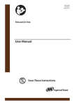
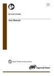
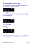
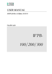
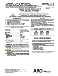
49124589
Revision A
August 2015
PacE Flow Controller
Installation and User Manual
Save These Instructions
Table of contents
Table of contents . . . . . . . . . . . . . . . . . . . . . . . . . . . . . . . . . . . . . . . . . . . . . . . . . . . . . 2
INSTALLATION. . . . . . . . . . . . . . . . . . . . . . . . . . . . . . . . . . . . . . . . . . . . . . . . . . . . . . . . . . . .3
OPERATION. . . . . . . . . . . . . . . . . . . . . . . . . . . . . . . . . . . . . . . . . . . . . . . . . . . . . . . . . . . . . . .3
Adjustment of Measuring System. . . . . . . . . . . . . . . . . . . . . . . . . . . . . . . . . . . . .4
Readjustment of Measuring System. . . . . . . . . . . . . . . . . . . . . . . . . . . . . . . . . . 4
TYPICAL INSTALLATION. . . . . . . . . . . . . . . . . . . . . . . . . . . . . . . . . . . . . . . . . . . . . . . . . . . .4
Maintenance. . . . . . . . . . . . . . . . . . . . . . . . . . . . . . . . . . . . . . . . . . . . . . . . . . . . . . . . . . . . 5
TROUBLESHOOTING. . . . . . . . . . . . . . . . . . . . . . . . . . . . . . . . . . . . . . . . . . . . . . . . . . . . . . .5
ORDER INFORMATION AND REPLACEMENT PARTS. . . . . . . . . . . . . . . . . . . . . . . . . . 6
49124589 Rev.A
WARNING
FAILURE OR IMPROPER SELECTION OR IMPROPER USE OF THE PRODUCTS AND/OR SYSTEMS DESCRIBED
HEREIN OR RELATED ITEMS CAN CAUSE DEATH, PERSONAL INJURY AND PROPERTY DAMAGE.
This document and other information from the Company, its subsidiaries and authorized distributors provide
product and / or system options for further investigation by users having technical expertise. It is important that you
analyze all aspects of your application including consequences of any failure, and review the information concerning
the product or system in the current product catalog. Due to the variety of operating conditions and applications for
these products or systems, the user, through its own analysis and testing, is solely responsible for making the final
selection of the products and systems and assuring that all performance, safety and warning requirements of the
application are met.
The products described herein, include without limitation, product features, specifications, designs, availability and
pricing are subject to change by the company and its subsidiaries at any time without notice.
NOTICE
Units can be supplied with air flow direction from left to right or right to left orientations. It is not
recommended to reverse flow direction in the field unless absolutely necessary.
INSTALLATION
Please read these instructions before installing this
product.
4. INSTALL with air flow in direction into “Inlet” and out
“System”(as noted on chassis housing).
IMPORTANT INSTALLATION INSTRUCTIONS FOR:
PACE 0.5”, 1” and 2”
5. DO NOT restrict the air flow with undersize piping or
fittings, unless maximum air flow is not needed.
1. DO NOT install the unit until you have read this entire
product information sheet.
6. INSTALLATION of a 5 micron rated filter upstream of
controller is recommended.
2. Product is specifically designed for clean, dry,
compressed air service, and use with any other
fluid (liquid or gas) is a misapplication. For example,
use with, or injection of certain hazardous liquids
or gases in the system (such as alcohol or liquid
petroleum gas) could be harmful to unit or result
in combustible condition or hazardous external
leakage. Manufacturer’s warranties are void in the
event of misapplication and manufacturer assumes
no responsibility for any resulting loss. Maximum
inlet pressure rating is 300 psig (21 bar) and a control
range of 0-160 psi (11 bar). Temperature range is -4 ˚F
to 176 ˚F (-20 ˚C to 80 ˚C).
7. WITH THE INDICATOR DIAL in the OFF position, allow
the inlet side pressure to slowly build and settle to
full pressure.
8. DO NOT fill tank on inlet side of system to full
pressure and then open ball valve blasting full
pressure to inlet of PacE Flow Controller. This may
cause system damage. Always throttle valve to
slowly increase pressure to controller.
9. TO CONTROL SYSTEM AIR turn adjustment knob
clockwise to raise the controlled air pressure and
counter clockwise to lower controlled air pressure.
3. INSTALL upstream of and as close as possible to
where controlled compressed air is needed.
OPERATION
To Operate: Once unit has been installed and all safety
requirements have been adhered, you are ready to begin.
If a higher System Pressure is initially set than desired,
simply turn the dial counter clock wise until the desired
System Pressure is achieved. Note: When dialing the
pressure to a lower setting excess air pressure will be
exhausted around the front dial. This will continue until
the System Pressure is satisfied.
Using the adjustment dial on the front of the PacE, turn
knob from the off position slowly in a clock wise motion
to the desired setting. Note that as a best practice a 10 psi
(7 bar) delta should be set between the Inlet Pressure and
System Pressure gauges.
The PacE is designed to react quickly to meet flow
demands. As a function of meeting this demand, the unit
will consume a small amount of air .05 cfm (0.025 dm^3/
s).
The indication numbers on the dial face are for reference
only and are not to be used an accurate indication of the
system set pressure.
49124589 Rev.A
Adjustment of Measuring System
Units are preadjusted at the factory and should require no
additional calibration at time of installation.
determine actual setting.
In the unlikely event that a unit needs readjustment
of its measuring system, please follow the following
recommendations.
Front Dial Indicator is for reference only and has no
bearing on unit functionality or actual Inlet or System
Pressure. Gauges (supplied) should be utilized to
Readjustment of Measuring System
1. INSTALL controller on air line with at least 110 psi
(7.5 bar) air pressure at the inlet port.
7. DIAL STOP SET can be used to prevent over
pressurization. To utilize the stop set, remove the
hold down screw “B”(Figure”B”), lift the hold down
washer “C” (Figure“B”). The stop set is located under
the dial face. Lift and turn the stop set to desired set
point, then replace the dial face, hold down washer
and hold down screw.
2. REMOVE lock button “A” (Figure “B”) from unit
revealing adjustment screw.
3. TURN adjusting knob to 100psi (7 bar) setting.
4. CHECK the gauge for 100 psig (7 bar) reading. If the
gauge reads other than 100 psig (7 bar) adjust screw
“A” (Figure”B”) with a screwdriver while holding the
adjusting knob on 100 psi (7 bar) setting. If more
than one half turn of screw “A” (Figure“B”) is required
to achieve 100 psig (7 bar).
A
5. TO CHECK ADJUSTMENT: when dial and gauge
are reading the same (100 psi ±2 psi; 7 bar ±0.14
bar), turn adjusting knob to 20 psi (1.4 bar). Unit
is adjusted when gauge reads 20 psig ±5 psig (1.4
bar ±0.34 bar). The ±2 psi and ±5 psig are accepted
tolerances of the most commonly used gauges.
C
B
6. DO NOT adjust screw “A” (Figure“B”) more than one
half turn when adjusting unit. If more than one half
turn is required to adjust it, additional problems with
the unit are involved and unit should be returned to
the vendor.
FIGURE “B”
TYPICAL INSTALLATION
FOR ROTARY COMPRESSOR
FOR RECIPROCATING COMPRESSOR
49124589 Rev.A
TYPICAL INSTALLATION
90 PSI (6.3 BAR)
85 PSI (5.9 BAR)
60 PSI (4.2 BAR)
115 PSI (8 BAR)
110 PSI (7.6 BAR)
105 PSI (7.3 BAR)
91 PSI +/- (6.3 BAR +/-)
Maintenance
IMPORTANT MAINTENANCE INSTRUCTIONS FOR PACE
FLOW CONTROLLER
3. MAINTENANCE SERVICE KITS are available for PacE
0.5”, 1” and 2”. Service should not be attempted
without proper tools, safety and mechanical
knowledge.
1. BEFORE ATTEMPTING TO SERVICE THIS UNIT, READ
THIS ENTIRE PRODUCT INFORMATION SHEET AND
TURN OFF AIR SUPPLY AND VENT BOTH SIDES OF
CONTROLLER.
2. FOR TROUBLE-FREE OPERATION, clean dry air and
proper lubrication of the PacE Controller is essential.
We recommend a 5 micron pre-filter for maximum
performance. Unit is factory lubricated and should
not be field lubricated.
TROUBLESHOOTING
When any of the following symptoms occur, contact technical services for recommendations:
A. Excessive relief venting
a. Unit is designed to bleed excess air pressure around the control knob, until system pressure has settled.
Note: Unit has a constant bleed of approximately .05cfm to maintain ability to react to system demands
without delay.
b. Secondary compressor in system side, causing over pressurization. See Typical Installation Diagram
c. Dial indicator was dialed above system requirements and then dialed down causing venting until system
pressure has settled to match dial reading.
B. Inability to attain high secondary pressure
a. Increase system pressure by slowly turning front dial clockwise until desired pressure is achieved on
gauge. Turn dial slow and allow system pressure to adjust and settle before increasing.
b. Blockage due to lack of lubrication or dirty air supply. Lack of lubrication is typically caused by excessive
moisture in air stream and /or lack of appropriate filtration. 5 micron pre-filter is recommended for
maximum product performance.
C. System pressure does not match dial indicator
a. Adjustment may be required (See Adjustment of Measuring System section of this guide for details)
D.Dial does not turn freely or is loose to the touch
a. Adjust black thumb screw on front of dial face until desired dial tension is achieved.
E. Unit not adjusting during cold weather
a. If operating below freezing (32 ˚F/ 0˚ C) no moisture should be allowed into controller inlet.
The above Symptoms are often caused by improper application, dirty and/or wet air supply. Only supply clean dry air
to inlet, achieved by a 5 micron pre-filter.
49124589 Rev.A
ORDER INFORMATION AND REPLACEMENT PARTS
Pace Flow Controller (NPT)
CCN
Description
49124365
PacE, 1/2” NPT, Left to Right Flow
49124373
PacE, 1” NPT, Left to Right Flow
49124381
PacE, 2” NPT, Left to Right Flow
49124399
PacE, 1/2” NPT, Right to Left Flow
49124407
PacE, 1” NPT, Right to Left Flow
49124415
PacE, 2” NPT, Right to Left Flow
Pace Flow Controller (BSP)
CCN
Description
49124423
PacE, 1/2” BSP, Left to Right Flow
49124431
PacE, 1” BSP, Left to Right Flow
49124449
PacE, 2” BSP, Left to Right Flow
49124456
PacE, 1/2” BSP, Right to Left Flow
49124464
PacE, 1” BSP, Right to Left Flow
49124472
PacE, 2” BSP, Right to Left Flow
Replacement Kits and Parts
CCN
Description
49124480
Kit, O-Ring Replacement, 1/2” PacE
49124498
Kit, O-Ring Replacement, 1” PacE
49124506
Kit, O-Ring Replacement, 2” PacE
49124512
Kit, Replacement Dial Knob
49124522
Gauge, Replacement
49124589 Rev.A
ingersollrandproducts.com
© 2015 Ingersoll Rand