1
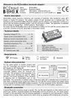
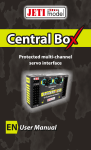
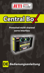
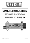
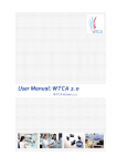
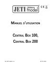
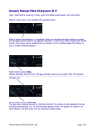
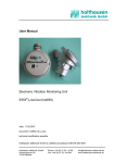
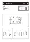
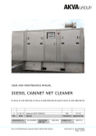
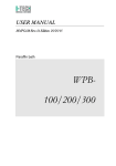
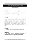
USER MANUAL
ELECTRONIC SWITCH
Main Switch
By JETI model s.r.o
25. 9. 2014
User Manual: Electronic switch Main Switch
1. Introduction
Main Switch is an electronic switch designed primarily for switching of the main power supply for an RC model. It adds
an element of safety when handling the model, without the need to physically disconnect the model´s batteries. A big
advantage of electronic switches in comparison to mechanical switches is, in general, their higher reliability as far as
vibration resistance is concerned. Another advantage of the electronic switch is its ability to withstand an unlimited number
of switching cycles. Electronic switches have no moving parts like contacts which would be worn out during the switching
processes, therefore their longevity is extremely high. Moreover, they are not prone to spontaneous and unexpected false
tripping with known disastrous effects. Last but not least, electronic switches offer a much lower inherent transient
resistance in comparison to mechanical switches. The Main Switch prevents the connectors from sparking when
connecting the batteries, thus it can also replace Anti Spark plugs.
The Main Switch is shipped with a magnetic switch. The magnetic switch instructions can be found on the
manufacturer´s website. It is also possible to use the optional RC Switch instead of the magnetic switch.
The Main Switch is primarily designed for switching the main power supply of the RC models, but can also be used in
applications where switching a DC power supply is needed.
2. Connection
The power supply is connected to the Main Switch using two input wires with cross sections of 6 or 8mm2. The output
voltage is available at two cables with cross sections of 6 or 8mm2. The output three-wire cable with the JR connector is
used for telemetry data transmission. The output three-pin connector is used to connect the supplied magnetic switch or
the RC Switch.
The Main Switch connects and disconnects the negative pole - , the + pole is always connected and is never
disconnected!
Fig. 1: Connection of input and output cables
Be sure to connect the power supply wires correctly; always connect the red cable to the + pole of the
accumulator, the black cable to the – pole of the accumulator. Pay attention when connecting outputs and inputs,
they must not be swapped. Failure to follow these requirements may result in irreversible damage to the Main
Switch!! Only connect batteries to the input IN and connect speed controllers, receivers, servos etc. to the output
OUT.
-2-
User Manual: Electronic switch Main Switch
Before switching on the electronic switch you should always connect the batteries first and only afterwards
switch on the system using the magnetic switch or the RC Switch. Follow this rule also for the switching off
procedure. Switch the system off first and disconnect the batteries only afterwards.
2.1 Connection of the Main Switch
The Main Switch measures the battery current and the voltage. If you do not need to get telemetry information from the
Main Switch, you do not have to connect the Ext. output. If you DO want to display then the telemetry the Main Switch Ext.
output must be connected to the Ext. Duplex receiver input. This also powers the measurement part of the Main Switch.
Fig. 2: Block diagram of the Main Switch
The ground (-) of the Main Switch Ext. is isolated. Do not connect the ground (-) of Magnetic switch / RC Switch to the
output ground of the Main Switch (-OUT).
2.2 Charging of the battery
The battery can be charged while connected to the Main Switch (be sure that the Main Switch is in the off state – the
green LED is off), but do not attempt to disconnect the battery while charging. The charging voltage is to be connected
directly to the battery (alternatively, to the battery through the switch input), but never connect charging voltage to the
switch output!! If it becomes necessary to disconnect the battery, disconnect the charging voltage first!! Failure to follow
these basic rules can destroy the Main Switch!!
-3-
User Manual: Electronic switch Main Switch
Fig. 3: Charging the battery
3. Installation
The Main Switch can be installed in models by taking advantage of mounting holes with rubber grommets that prevent
vibration transfer. The input and output wire connections must be adequately dimensioned for the size of the transmitted
current.
The connectors and the connecting wires used must be sufficiently large to transfer the required current. The G5.5
connectors are recommended for the current of up to 100A, for the current of up to 200A use the G8 connectors.
4. Telemetry
The Main Switch can measure the voltage, current, consumed capacity of the battery connected in the model and also the
Main Switch temperature. Alarms can be set to monitor maximum current, minimum voltage, maximum consumed
capacity, and maximum temperature.
-4-
User Manual: Electronic switch Main Switch
Use the JETIBOX or the DC/DS transmitters from JETI model (in the JETIBOX emulator) for parameter adjustment and
data readout. After the JETIBOX is connected to the Main Switch, the sensor identification is shown and in the second line
also the preadjusted actual measured data. By a long push of button R (right) a fast deletion of all measured data can be
triggered (min. and max. voltage, max. current, average current, runtime, capacity). Fast deletion is indicated in the first
line of the display by an asterisk „*“.
MENU: ACT. VALUES –
Volt. / Current – displays actual measured voltage and current passing through the switch. By simultaneously pushing
arrows R and L (right and left) the zero value of the sensor current is calibrated. The actual measured current value is
added to the zero current display, i.e. the so called zero shift.
Capacity – shows the actual consumed capacity.
Run Time – shows the total time of current passage through the switch. Included is also the time when the current has
exceeded the adjusted current value Start Trigger in the SETTING menu.
Temperature – shows the current temperature of the Main Switch.
MENU: MIN / MAX – Display of extreme voltages and currents that occurred during the measurement. The extreme
recordings are deleted automatically or can be deleted in the menu „SETTING – Erase Data“. Automatic deletion occurs
when the switch has just been connected to the voltage supply and the current, as set in the menu Setting-Start Trigger, is
exceeded. If after connection of the switch the set current is not exceeded, values of the previous switch operation will be
displayed.
U MIN / MAX – Shows the minimum and maximum value of the measured voltage.
I AVG / MAX – Shows the average value of the measured current and its maximum.
Temperature MIN/MAX – Shows the minimum and maximum operating temperature of the Main Switch since the last
reset.
MENU: SETTING – basic setting of the switch
Start Trigger – setup of a current value, at which after switch connection, the recording of values like minimum, maximum
and current transit time starts. If the adjusted value is 0A, values will be recorded immediately after the connection of the
switch to its power supply and reading the data of the previous operation will not be possible.
Erase Data – by pushing arrows R and L (right and left) simultaneously the records of measured parameters will be
deleted.
First Parameter – adjustment of the display of the first parameter in the JETIBOX LCD, which is shown in the second line
of the basic switch menu (the first line shows the identification, for instance MS 200)
Second Parameter – adjustment of the display of the second parameter in the JETIBOX LCD, which is shown in the
second line of the basic sensor menu (the first line shows the identification, for instance MS 200)
Auto. Erase – This function of automatic data deletion after overstepping the trigger level can be activated or deactivated.
MENU: ALARMS – setting of individual alarms.
If one of the adjusted parameters becomes exceeded, the JETIBOX LCD will in the second line of the basic menu
alternately show the original display with the pertinent alarm and the transmitter module siren will emit an acoustic alarm.
The first tone is a revelation signal and the second one is signaling a Morse code character of the relevant alarm. If the
alarm is set to OFF, this kind of alarm will be switched off.
-5-
User Manual: Electronic switch Main Switch
Voltage Alarm (alarm U ..- ) – adjustment of the value of voltage signaling. If the measured voltage decreases beyond the
set value, the voltage alarm U will be activated.
Current Alarm (alarm I .. ) – adjustment of the value of current signaling. If the measured current increases beyond the set
value, the current alarm I will be activated.
Capacity Alarm (alarm C -.-. ) – adjustment of the signaling value of consumed capacity. If the adjusted value of maximum
consumed capacity is exceeded, alarm C will be activated.
Temperature Alarm (alarm T - ) – adjustment of the value of high temperature signaling for the Main Switch device. If the
measured temperature exceeds 85°C, the “high temperature” alarm will be activated.
MENU: SERVICE – by pressing button D (arrow down) you will change the display to show the firmware version and to
renewal of the switch default setting.
Factory Defaults – by simultaneous pressing of arrows R and L (right and left) the factory settings of the Main Switch are
loaded.
M200 v. xx.xx ID xxxxx:xxxxx – product marking with firmware version and series number (ID).
Particular phases of current measurement
A – when after switching on the current did not exceed the set value Start
Trigger. Measured values (U MIN / MAX, I AVG / MAX, Capacity, Run
Time) correspond with measured values of the previous operation.
B – the value Start Trigger has been exceeded.
Previous measured values (U MIN / MAX, I AVG / MAX, Capacity, Run
Fig. 4: Phases of current measurement
Time) will be deleted and actualized by the actual measurement course.
C – the set current has been exceeded and the current alarm has been activated.
D – the measured current decreased beyond the set alarm value, alarm will be cut off. The measured current decreased
beyond the set level Start Trigger. The timer Run Time is switched off. Recording of extremes and consumed capacity
continuous.
5. Update
The Main Switch allows updating of its firmware via PC. Updating is done using the JETI USB adapter.
Procedure:
o
Find the program to update to the latest firmware on the manufacturer´s website under „Downloads“. Save it to
your computer.
o
Connect the USB adapter to your computer. The procedure of installing the drivers for the USB adapter is
included in the USB adapter manual.
o
Run the firmware update on your PC.
o
Connect the USB adapter to the Main Switch (Ext. output) using a three-wire cable.
-6-
User Manual: Electronic switch Main Switch
o
After connecting the device the update will begin.
Fig. 5: Update
6. Technical data
Technical data:
Main Switch 100
Main Switch 200
Input voltage
Sustained output current
Power consumption in off-mode
@51V
Power supply via Ext. for telemetry
Accuracy of voltage measurements
Accuracy of current measurements
Operating temperature
Weight including the cables
Dimensions of the module
9 – 51 V
100 A
9 – 51 V
200 A
110 uA
110 uA
4 - 8.4V
0,13%
1%
- 20°C up to +85°C
110 g
80x36x23 mm
4 - 8.4V
0,13%
1%
- 20°C up to +85°C
140 g
80x36x25 mm
-7-
User Manual: Electronic switch Main Switch
7. Menu structure in the JETIBOX
Fig. 6: Main Switch tree diagram
8. Warranty, service
This product is covered by warranty for 24 months after the day of purchase provided that it has been operated in accordance
with these instructions at the specified voltage and is not mechanically damaged. When claiming warranty repairs for the product,
always attach a proof of purchase. Warranty and post-warranty service is provided by your dealer or the manufacturer.
Technical support
In case you are not sure about the setup or some functions of the product, do not hesitate to contact our technical support. You
can contact either your dealer, or directly the manufacturer JETI model s.r.o.. For further information see our webpages
www.jetimodel.cz.
The manufacturer: JETI model s.r.o. Příbor, www.jetimodel.cz
-8-