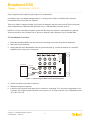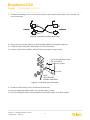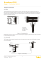
1
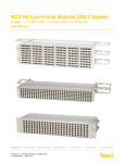
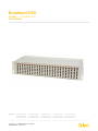
Broadband DSX
Copper :: 010-0000-1403
User Manual
Applys to : 010-0000-0401 :: 010-0000-0402 :: 010-0000-0471 :: 010-0000-1401 :: 010-0000-1402 ::
010-0000-1403 :: 010-0000-1404 :: 010-0000-1448 :: 010-0000-1460 :: 010-0000-1471 ::
010-8401-0401 :: 010-8401-0407 :: 010-8401-0410 :: 010-8411-0401 :: 010-8411-0407 ::
© Telect, Inc., All Rights Reserved, 109374-4
1.509.926.6000 :: telect.com
Broadband DSX
Copper :: Part Number 109374-3
Table of Contents
Chapter 1: Description����������������������������������������������������������������������������������������������������������1
1.1 Overview�������������������������������������������������������������������������������������������������������������������������1
1.1.1 Capabilities�������������������������������������������������������������������������������������������������������������1
1.1.2 Features������������������������������������������������������������������������������������������������������������������1
1.1.3 Applications�������������������������������������������������������������������������������������������������������������2
1.1.3 Part Numbers����������������������������������������������������������������������������������������������������������2
1.2 Main Assemblies�������������������������������������������������������������������������������������������������������������3
1.3 Specifications������������������������������������������������������������������������������������������������������������������4
1.3.1 Electrical�����������������������������������������������������������������������������������������������������������������4
1.3.2 Environmental���������������������������������������������������������������������������������������������������������4
Chapter 2: Installation�����������������������������������������������������������������������������������������������������������7
2.1 Installation Considerations����������������������������������������������������������������������������������������������7
2.1.1 Location and Space������������������������������������������������������������������������������������������������7
2.1.2 Tools and Equipment�����������������������������������������������������������������������������������������������7
2.1.3 Technical Support����������������������������������������������������������������������������������������������������7
2.2 Inspection�����������������������������������������������������������������������������������������������������������������������7
2.3 Installation Procedure�����������������������������������������������������������������������������������������������������8
Chapter 3: Electrical����������������������������������������������������������������������������������������������������������� 11
3.1 Power���������������������������������������������������������������������������������������������������������������������������� 11
3.1.1 Tracer Lamp���������������������������������������������������������������������������������������������������������� 11
3.2 Signal Flow�������������������������������������������������������������������������������������������������������������������12
Chapter 4: Service��������������������������������������������������������������������������������������������������������������13
4.1 Owner Maintenance������������������������������������������������������������������������������������������������������13
4.1.1 Replacing The Tracer Lamp LED�������������������������������������������������������������������������� 13
4.1.2 Technical Support��������������������������������������������������������������������������������������������������13
4.2 Troubleshooting: Cross-Connected Signals����������������������������������������������������������������� 13
4.3 In-Warranty Service������������������������������������������������������������������������������������������������������13
4.4 Out-Of-Warranty Service����������������������������������������������������������������������������������������������13
4.5 Repacking for Shipment�����������������������������������������������������������������������������������������������14
List of Figures
Figure 1 - Model 010-0000-0401������������������������������������������������������������������������������������������1
Figure 2 - System-Level Applications�����������������������������������������������������������������������������������2
Figure 3 - Chassis�����������������������������������������������������������������������������������������������������������������3
Figure 4 - Backplane�������������������������������������������������������������������������������������������������������������3
Figure 5 - DSX Module���������������������������������������������������������������������������������������������������������4
Figure 6 - Dimensions�����������������������������������������������������������������������������������������������������������5
Figure 7 - Connecting the Network Element Equipment������������������������������������������������������� 8
Figure 8 - Connecting the Messenger Wire�������������������������������������������������������������������������� 9
Figure 9 - Connecting the Ground Wire�������������������������������������������������������������������������������� 9
Figure 10 - Terminating a Bus��������������������������������������������������������������������������������������������� 11
Figure 11 - Tracer Lamp����������������������������������������������������������������������������������������������������� 11
Figure 12 - Signal Flow�������������������������������������������������������������������������������������������������������12
© Telect, Inc., All Rights Reserved, 109374-4
1.509.926.6000 :: telect.com
II
Broadband DSX
Copper :: Part Number 109374-3
Chapter 1: Description
1.1 Overview
Telect’s Broadband Digital Signal Cross-Connect (DSX) is a high-density device for cross- connecting DS3,
STS-1, and STS-3 signal types from broadband equipment, such as digital radio, fiber-optic multiplexers, and 3:3
or 3:1 DCS.
Figure 1 - Model 010-0000-0401
1.1.1 Capabilities
• Virtually “hitless” patching with terminate-before-break TwistLokTM (TLJTM) jacks
• Backplane can be preterminated and cross-connect assignments prewired
• Bidirectional monitoring
1.1.2 Features
• Plug-in DSX cards to turn up circuit
• Holds up to 48 modules (8” x23” chassis)
• Uses industry standard patch cords
• Mini-WECO jacks and BNC, TNC, or 1.6/5.6 connectors
• Cable tie-down bars
© Telect, Inc., All Rights Reserved, 109374-4
1.509.926.6000 :: telect.com
1
Broadband DSX
Copper :: Part Number 109374-3
1.1.3 Applications
B ro a d b a n d
DSX
DS3
DCS
D igita l R ad io
S T S -1
M 13 M U X
FOT
Figure 2 - System-Level Applications
1.1.4 Part Numbers
The information in this manual applies to the following part numbers:
Chassis #
Height
Width
Positions
Connectors
010-0000-0401
4”
19”
18
BNC
010-0000-0471
2”
19”
8
BNC
010-0000-0402
010-0000-1401
010-0000-1402
010-0000-1403
010-0000-1404
010-0000-1448
010-0000-1460
010-0000-1471
4”
4”
4”
4”
4”
8”
8”
2”
19”
23”
23”
23”
23”
23”
23”
23”
18
24
24
24
24
48
48
10
BNC
BNC
BNC
BNC
BNC
BNC
BNC
BNC
Module #
Jacks
# of Ports
010-8401-0407
Mini-WECO
3
010-8401-0401
010-8401-0410
010-8411-0401
010-8411-0407
© Telect, Inc., All Rights Reserved, 109374-4
1.509.926.6000 :: telect.com
Mini-WECO
4
Mini-WECO
6
Standard WECO
4
Standard WECO
3
2
Tracer Lamp
Terminations
PJ
PJ
PJ
PJ
NA
WW
PJ
PJ
PJ
PJ
Broadband DSX
Copper :: Part Number 109374-3
1.2 Main Assemblies
Figure 3 - Chassis
Part #010-0000-0401 Shown
Pin Sockets
Cross-Connects
®
18
17
16
15
14
13
12
11
10
9
8
7
6
5
4
3
2
1
OX
OX
IX
IX
O
O
I
I
Equipment Connections
BNC Connectors
BATT A
RTN A
RTN B
BATT B
C. GND
COM
MAJ
ALARMS
MIN
PWR
Ground Lug
(Placement varies on each chassis.
Look for this symbol.)
Figure 4 - Backplane
© Telect, Inc., All Rights Reserved, 109374-4
1.509.926.6000 :: telect.com
3
Broadband DSX
Copper :: Part Number 109374-3
 Figure 5 - DSX Module
1.3 Specifications
1.3.1 Electrical
Digital Signal: E3 (34.368 Mbps), T3 (44.736 Mbps), STS-1 (51.84 Mbps), or STS-3 (155 Mbps)
Insertion Loss: 0.6 dB ±0.55, 8 MHz to 240 MHz, at signal rate
Return Loss: ≤ -15 dB, 8 MHz to 240 MHz, STS-3 signal rate,≤ -26 dB, T3/E3/STS-1 signal rates
Crosstalk: ≤ -60 dB, 8 MHz to 240 MHz, at signal rate
Monitor Level: 20 dB ±1.5 dB below signal level Contact Resistance: ≤ 0.01Ω
Characteristic Impedance: 75Ω
Tracer Lamp LED: Draws 9 mA
1.3.2 Environmental
Temperature: –67o to 185oF (–55o to 85oC)
Thermal Shock: Per MIL-STD 202, method 107D
Humidity: To 95% noncondensing (operating and nonoperating)
© Telect, Inc., All Rights Reserved, 109374-4
1.509.926.6000 :: telect.com
4
Broadband DSX
Copper :: Part Number 109374-3
C hassis #010-0000-0401 S how n
4 .0 in .
(10 .16 c m )
4 .0 in .
(10 .16 c m )
M odule #010-8401-0401 S how n
Figure 6 - Dimensions
© Telect, Inc., All Rights Reserved, 109374-4
1.509.926.6000 :: telect.com
5
Broadband DSX
Copper :: Part Number 109374-3
 This page intentionally left blank.
© Telect, Inc., All Rights Reserved, 109374-4
1.509.926.6000 :: telect.com
6
Broadband DSX
Copper :: Part Number 109374-3
Chapter 2: Installation
2.1 Installation Considerations
!
CAUTION
CAUTION! Only qualified personnel may install and maintain this product.
!
CAUTION
CAUTION! Do not supply power until all connections are made in accordance with requirements
specified in local electrical codes. Protect this equipment with an approved fuse or breaker sufficiently
rated to interrupt power at -48 Vdc at 2 amps, or as specified on the device. Only use components and
crimping tools approved by agencies or certify- ing bodies recognized in your country or region such as
Underwriter’s Laboratories (UL), TUV, etc.
!
CAUTION
CAUTION! Install this equipment in locations accessible ONLY to qualified persons.
!
ALERT
ALERT! These instructions presume you have verified that the Telect equipment being installed is
compatible with the rest of the system, including power, ground, circuit protection, signal characteristics,
equipment from other vendors, and local codes or ordinances.
2.1.1 Location and Space
Depending on its size, the Broadband DSX mounts in 19” or 23” WECO-spaced racks (1-inch-on- center
mounting holes) and uses 2”, 4”, or 8” of vertical space.
2.1.2 Tools and Equipment
No special tools or equipment are required.
2.1.3 Technical Support
By e-mail: [email protected]
By phone: 888-821-4856 or 509-921-6161
2.2 Inspection
Please read these instructions carefully before beginning installation. If you need assistance, call Technical
Support at 1-888-821-4856 (domestic calls), or 509-921-6161 (Option 2), or email us at [email protected].
© Telect, Inc., All Rights Reserved, 109374-4
1.509.926.6000 :: telect.com
7
Broadband DSX
Copper :: Part Number 109374-3
Inspect equipment after unpacking and compare it to the packing list.
Immediately report any shipping damage, defects, or missing parts to Telect at 1-800-551-4567. Keep all
documentation that comes with your shipment.
Telect is not liable for shipping damage. If the product is damaged, notify the carrier and call Telect’s Customer
Service Department at 1-800-551-4567 (domestic only) or 1-509-926-6000 for further recourse.
NOTE: For service or warranty information, please visit the telect.com website, or email inquiries to getinfo@
Telect.com and click on the “Support” tab, or phone us at 800-551-4567 (domestic only) or 509-926-6000.
2.3 Installation Procedure
1. Mount the Broadband DSX to the rack with the four mounting screws that come with the equipment.
2. Remove the top tie-down bar.
3. Starting with the lowest Broadband DSX in the rack and working up, connect the network ele- ment (NE)
equipment to the lower pairs of connectors:
4
3
2
1
OX
B AT T A
RTN A
RTN B
B AT T B
C. GND
COM
MAJ
ALARM S
M IN
PW R
IX
E q u ip m e n t
Tra n sm it
O
I
R e ce ive
Figure 7 - Connecting the Network Element Equipment
4. Secure the cables to the lower tie-down bar.
5. Reattach the upper tie-down bar.
6. Install the cross-connects at the upper pairs of connectors, connecting “IX” of one piece of equipment to “OX”
of another. The equipment must have both cross-connects: “IX” of Equip- ment A to “OX” of Equipment B, and
“IX” of B to “OX” of A.
© Telect, Inc., All Rights Reserved, 109374-4
1.509.926.6000 :: telect.com
8
Broadband DSX
Copper :: Part Number 109374-3
7. Connect the messenger wire to one of the pin sockets or wire wrap pins that pertain to the IX and OX of a
cross-connect pair:
Figure 8 - Connecting the Messenger Wire
8. Secure the cross-connect cables from other Broadband DSXs to the upper tie-down bar.
9. 9. Slide the plastic designation-label holders onto the DSX modules.
10. Connect a ground wire (14 AWG, minimum) with ring terminal to the ground lug:
Ground lug placement varies
on each chassis.
Look for this symbol.
(no paint)
NOTE:
GROUND WIRE
SHOWN IS GENERIC
Figure 9 - Connecting the Ground Wire
11. Connect the office battery to the Power/Alarm Terminal Strip.
12. Insert the appropriate DSX modules to turn up the circuits you want.
13. Fill out the designation labels and insert them into the plastic holders on the DSX modules.
© Telect, Inc., All Rights Reserved, 109374-4
1.509.926.6000 :: telect.com
9
Broadband DSX
Copper :: Part Number 109374-3
 This page intentionally left blank.
© Telect, Inc., All Rights Reserved, 109374-4
1.509.926.6000 :: telect.com
10
t
Broadband DSX
Copper :: Part Number 109374-3
Chapter 3: Electrical
3.1 Power
The Broadband DSX is passive equipment. It accepts –48V office battery power to light the tracer lamp (TL)
LED on the front of the DSX modules. This power connects to the Power/Alarm Terminal Strip at the back of the
equipment. The strip terminates a bus on the chassis backplane; all DSX module connectors on the backplane
tap into the signal lines of this bus:
4
3
2
OX
BATT A
RTN A
RTN B
BATT B
C.GND
COM
MAJ
MIN
PWR
B AT T A
RTN A
RTN B
1
B AT T B
C. GND
COM
MAJ
ALARM S
M IN
PW R
BATT A
RTN A
RTN B
BATT B
TL
COM
MAJ
MIN
PWR
IX
O
Rear
View of the Chassis
I
Any Module
Connector on
the Inside of the
Backplane
Figure 10 - Terminating a Bus
NOTE: When using an 8” chassis, you must connect both power supplies to power the chassis. This can be done
by “daisy-chaining” them together.
3.1.1 Tracer Lamp
The TL lights only when a plug is inserted into one of the monitor jacks on the front of a DSX module, as shown
in the following figure.
Figure 11 - Tracer Lamp
© Telect, Inc., All Rights Reserved, 109374-4
1.509.926.6000 :: telect.com
11
Broadband DSX
Copper :: Part Number 109374-3
You can also connect TLs of cross-connected modules by attaching the messenger wire to one of the backplane
pin sockets or wire wrap pins that corresponds to each of the connected modules. When one TL lights, the other
flashes for about 30 seconds and then lights steady.
3.2 Signal Flow
The Broadband DSX generates no signals of its own. Connectors on the outside of the backplane are tied to
PCB connectors on the inside. The “in” (I) and “out” (O) circuits connect to their corresponding cross-connects
(IX, OX) only when a DSX module is inserted in a connector—the “in” and “out” jacks on the module close the
circuits, as long as the jacks have no patch cords inserted.
Cables attached to the cross-connects on the backplane (IX, OX) take the “out” signals of one piece of equipment to the “in” circuit of another and vice versa. Inserting a patch cord in a module jack breaks the circuit established by the cross-connect cables, diverting the signal through the cord to another location.
Backplane Connector
BNCs
OX
M
O
I
O
OX
IX
I
M
Figure 12 - Signal Flow
© Telect, Inc., All Rights Reserved, 109374-4
1.509.926.6000 :: telect.com
12
IX
O
I
Broadband DSX
Copper :: Part Number 109374-3
Chapter 4: Service
!
CAUTION
CAUTION! Only qualified technicians may install and maintain this product.
4.1 Owner Maintenance
Telect’s Broadband DSX does not need preventive maintenance. The only service you can perform is to replace
defective assemblies:
• DSX module
• Chassis
• Tracer lamp LED
4.1.1 Replacing The Tracer Lamp LED
Pull the LED assembly and plastic holder straight out.
If LED polarization is not correct, the replacement will not work. Orient the new LED in the plastic holder the
same as the original. The shape of the LED holder slot in the DSX module is “keyed” for proper LED insertion.
4.1.2 Technical Support
By e-mail: [email protected]
By phone: 888-821-4856 or 509-921-6161
4.2 Troubleshooting: Cross-Connected Signals
Check for correct and firm cable connections at the termination and cross-connect points of the Broadband DSX.
4.3 In-Warranty Service
Contact Telect’s quality call center at 877-471-7245 or e-mail us at [email protected]. Telect will ship a new
replacement product, along with a return shipping label and authorization information. When you receive your
replacement product, pack up the defective product and return it to Telect using the return label, box and any
additional information provided.
4.4 Out-Of-Warranty Service
Follow the In-Warranty directions above. Telect charges a processing fee for out-of-warranty service, and you
must submit a Purchase Order along with a Return Material Authorization (RMA) before returning equipment.
The processing fee guarantees a repair estimate and is credited against actual material and labor costs. Call
Telect’s quality call center at 877-471-7245 for more information.
© Telect, Inc., All Rights Reserved, 109374-4
1.509.926.6000 :: telect.com
13
Broadband DSX
Copper :: Part Number 109374-3
4.5 Repacking for Shipment
1. Tag the equipment showing owner’s name, address, and telephone number, together with a detailed
description of the problem.
2. Use the original shipping container if possible. If you do not have it, package the equipment in a way to
prevent shipping damage. Include the RMA inside the container and legibly print the RMA number on the
outside of the package, near the shipping address.
3. Insure the package.
© Telect, Inc., All Rights Reserved, 109374-4
1.509.926.6000 :: telect.com
14