1
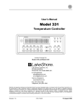
Lake Shore Model 321 Autotuning Temperature Controller User’s Manual
P-321-2-1.bmp
Figure 2-1. Typical Model 321 Rear Panel
2.3
DEFINITION OF REAR PANEL CONNECTIONS
This paragraph provides a description of the Model 321 rear panel connections. The rear panel consists
of the power and fuse assembly, Serial I/O Connector, Analog Output Connector, Sensor Input
Connector, and Heater Output Connector.
CAUTION: Verify that the AC Line Voltage shown in the window on the fuse drawer
corresponds to that marked on the rear panel, and that both these settings are
appropriate for the intended AC power input. Also remove and verify the proper
fuse is installed before inserting the power cord and turning on the instrument.
CAUTION: Always turn off the instrument before making any rear panel connections. This
is especially critical when making sensor to instrument connections.
Power and Fuse Assembly. The power and fuse assembly is the primary entry and control point for
AC power to the unit. The assembly consists of two parts: power line jack and the fuse drawer. The line
cord is connected to the power line jack. Power to the unit is controlled by the power switch located on
the rear panel. Press the right side of the switch for On (l) and the left side for Off (O). The fuse drawer
contains a 1.5 A 3AG Slow Blow fuse for 100 – 120 VAC or a 0.75 A 5×20 mm T fuse for 220 – 240
VAC. Refer to Paragraph 6.2 for changing power settings and fuse rating.
Serial I/O Connector. The Serial I/O (Input/Output) Connector accepts a standard RJ-11 telephone
connector. To connect to the User’s computer, the optional Model 2001 RJ-11 to RJ-11 10-foot Cable,
Model 2002 RJ-11 to DB-25 Adapter, and Model 2003 RJ-11 to DE-9 Adapter are available as
accessories from Lake Shore. Refer to Chapter 4 for Serial Interface setup and commands. Refer to
Chapter 5 for further information on the serial interface connector accessories.
Analog Output BNC Connector. The analog output is available on one Bayonet Nut Connector (BNC).
The signal is on the center conductor while the outer casing is for ground. In the default setting, the
analog output provides a 0 – 10 volt output corresponding to 0 – 1000 K (10 mV/K). The user can also
redefine the scaling of this output. Refer to Chapter 3 for further information.
Sensor Input Connector. A sensor input connector is provided for attaching temperature sensor to
the unit. Always turn off the instrument before connecting the sensor. Refer to Paragraph 2.6 for further
information on setting up the sensor input.
Heater Connectors. Banana jacks provide HI, LO, and GND heater connections (25 Ω, 25 W Heater
recommended). Refer to Paragraph 2.10 for further information on heater connection setup.
2-2
Installation