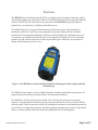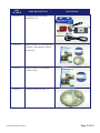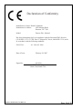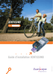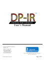
1
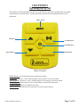
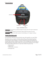
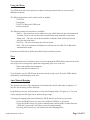
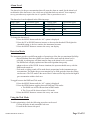
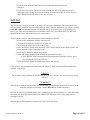
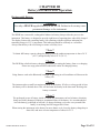
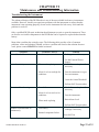
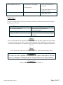
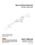
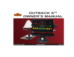
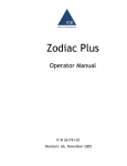
TM
User’s Manual
Heath Consultants Incorporated
Houston, TX
Phone: 713-844-1300
Fax: 713-844-1309
1-800-HEATH-US
www.heathus.com
102105-0 DP-IR MANUAL REV M
Heath...Safety, Leadership, Innovation, Performance
Then, Now, and Tomorrow
Page 1 of 35
Notice
The contents of this user’s manual are proprietary to Heath Consultants Incorporated
(HEATH). Reproduction in whole or in part of this manual is prohibited without the
express written consent of HEATH. HEATH operates under a continual product
improvement program and reserves the right to make improvements and or changes
without prior notification. This manual supersedes all previous manuals for this
instrument.
Detecto Pak-Infrared™ and DP-IR™ are HEATH registered trademarks.
The DP-IR is protected by patents and patents pending.
© COPYRIGHT 2007 Heath Consultants Incorporated. All rights reserved.
102105-0 DP-IR MANUAL REV M
Page 2 of 35
Warnings:
It is essential that users of this instrument read, understand, and follow the instructions
for operation and maintenance and the precautions contained in this manual to insure
that the instrument is used in a proper and safe manner. For potential situations where
injury may occur to the operator or damage the instrument, a warning enclosed in a
box will be shown to alert the operator.
**Warning**
Perform any and all maintenance in a location known to be nonhazardous.
**Warning**
To reduce the risk of ignition of a flammable or explosive atmosphere,
batteries must be changed or recharged only in a location known to be
non-hazardous.
**Warning**
No attempt should be made to repair the instrument. Should the
instrument not work properly or indicate an error or warning, refer to
the troubleshooting section of this manual.
**Warning**
Substitution of components may impair intrinsic safety. No userserviceable components contained within this instrument.
102105-0 DP-IR MANUAL REV M
Page 3 of 35
Table of Contents
Notice .......................................................................................................................2
Warnings ..................................................................................................................3
Overview ..................................................................................................................6
Chapter I
DP-IR System Specifications ...................................................................................7
DP-IR System Components .....................................................................................8
Optional Accessories ..............................................................................................10
Chapter II
Operating the DP-IR ..............................................................................................11
Keypad ...............................................................................................................11
User Interface .....................................................................................................12
External Features ................................................................................................13
Turning the DP-IR On/Off .................................................................................13
Using the Menu ..................................................................................................14
Zero ....................................................................................................................14
Auto/Manual Ranging ........................................................................................14
Alarm Level ........................................................................................................15
Detection Modes ................................................................................................15
Using the Tick Mode ..........................................................................................15
Self-Test .................................................................................................................16
Chapter III
Battery/External Power Operation
Rechargeable Battery .........................................................................................18
Battery Charging ................................................................................................19
Battery Replacement ..........................................................................................19
External Power ...................................................................................................19
102105-0 DP-IR MANUAL REV M
Page 4 of 35
Chapter IV
Serial Data Communication ....................................................................................20
Chapter V
Surveying with the DP-IR .......................................................................................21
Using the Bar Hole Probe ........................................................................................22
Chapter VI
Maintenance and Troubleshooting Information
Troubleshooting the Instrument ...........................................................................23
Maintenance .........................................................................................................24
Chapter VII
Service Information
Warranties and Warranty Repair ..........................................................................25
Obtaining Service ................................................................................................25
DP-IR Parts List ......................................................................................................26
DP-IR Daily Self-Test and Calibration Log ............................................................33
Declaration of Conformity ......................................................................................34
Contact Information ................................................................................................35
102105-0 DP-IR MANUAL REV M
Page 5 of 35
Overview
The HEATH Detecto Pak-Infrared (DP-IR™) uses highly advanced optical technology capable
of detecting methane gas utilizing the Infrared Controlled Interference Polarization Spectrometry
method. The DP-IR is the latest leak survey instrument from HEATH that greatly improves
productivity, cost and safety of walking and mobile surveys.
The DP-IR functions by using an infrared optical gas detection system. This instrument is
intended to replace the current surveying equipment using the traditional Flame Ionization
method with next-generation technology utilizing an infrared light beam, eliminating the need
for expensive gas cylinders and refill systems. It is designed to be highly selective to detecting
methane gas and will not false alarm on other hydrocarbon gases which may be encountered
during a normal natural gas leak survey.
Figure 1: The DP-IR uses advanced infrared optical technology to achieve high sensitivity
to methane gas.
The DP-IR operates under a variety of field conditions, including cold and hot temperatures. Its
rugged design will stand up to normal field use and operating conditions.
The DP-IR has a built-in self-test function that will verify that the instrument is operating
properly. Using the internal calibration cell, the operator performs the self-test as part of a daily
start-up routine. While in operation, the DP-IR continuously monitors several internal parameters
to ensure that it is functioning properly. Should any of these parameters go outside of operational
limits, a constant audible alarm will sound and an ERROR icon will be displayed.
102105-0 DP-IR MANUAL REV M
Page 6 of 35
CHAPTER I
DP-IR System Specifications
Detection Method:
Infrared Controlled Interface Polarization Spectrometer
Measurement Range:
0-100,000 PPM
1-100% Gas
Display Range:Auto Ranging:Manual Ranging:
PPM: 0-10,000PPM scale: 0-10,000
% Gas: 1-100%% Gas: 0-100%
Sensitivity:
0-1000 PPM: 1 PPM
1000-10,000 PPM: 5 PPM
1-100% Gas: 0.5%
Accuracy:
Greater of +/- .5% or +/- 10% of reading (typical, std conditions) (% Gas on manual mode)
Detection Alarms Modes: Digital Methane Detection (DMD):
Audible tone when detection threshold is exceeded
Adjustable Alarm Level from 1 to 9000 PPM
Tick:
Continuous audio tone relative to concentration
System Fault Warning:
Audible tone and indication on the display
Self-Test & Calibration:
Built in Self-Test and Calibration function verifies operation and adjusts calibration for maximum sensitivity. Test gas cell integrated within the instrument.
Compliance:EN 61326-1
Conducted Emissions Class B
EN 61326-1
Radiated Emissions Class B
EN 61000-4-2 4kV/8kV
ANSI C63.4 Class BEN 61000-4-3 3 V/M
FCC 47 CFR Part 15 Class B
Dust Filter:
Replaceable filter provides dust protection. Easy change out quick disconnect filter cap.
Display:
Large easy to read backlit LCD (.75” Numeric)
Operating Temperature:
0 to + 122° F (-17 to 50° C) (nominal battery voltage)
Humidity:
5 to 95% RH, non-condensing
Enclosure:
IP54 (Water splash and Dust resistant)
Instrument Weight:
5.6 lbs.
Carrying Case:
13 lbs. empty; 21 lbs. filled
24.5” x 21” x 9”
Power Supply:
Internal rechargeable Li-ion battery or
External 12 VDC car battery with optional power conditioner
Battery Operating Life:
8 hours at 32° F with out backlight on
Battery Charger:
External, in-line, 110 - 240 VAC, 50/60 hertz. 10 hours to 90% charge
Shoulder Strap:
Single over the shoulder padded strap
Speaker Volume:
108 dBs @ Alarm port (A-fast)
Survey Probe:
Quick connect fitting with locking clasp. Adjustable length from 25” to 41”
Bar hole Probe:
Std: 20”; Optional 36”
Intrinsic Safety:
Class 1 Division 1 Group D T3
UL 913 MetLab #E112840
102105-0 DP-IR MANUAL REV M
Page 7 of 35
DP-IR System Components
This chapter describes the features of the DP-IR. Please refer to Figure 2 for illustrations of
individual parts.
Survey
Probe
DP-IR
Replacement
Filters
Instruction CD
Battery
Charger
Bar Hole
Probe
Hand and
Shoulder
Strap
Carrying
Case
Figure 2: System Components
Instrument
This is the primary component of the DP-IR surveying system. In addition to the gas detection
capability, it contains the user interface, data logging interfaces, power connector and the
surveying probe connection.
Carrying Strap
The DP-IR has a detachable hand strap secured to three mounting points on the instrument.
There is also a padded shoulder strap to accommodate different carrying preferences.
Battery Charger
The battery charger is provided to recharge the instrument after use. The charger is a universal
110 - 240 VAC, 50/60 hertz with a charging indicator. Universal adaptors are provided to convert
the style plug for different types of receptacles.
102105-0 DP-IR MANUAL REV M
Page 8 of 35
Instruction CD
The instruction CD contains the following items:
1. This instruction manual, which provides instructions on the use and operation of the
instrument.
2. Additional HEATH product information.
3. HEATH contact information.
Carrying Case
The carrying case provides protection for the instrument during storage or transportation. The
instrument should be kept in the case while not in use.
Bar Hole Probe
The bar hole probe allows for underground gas measurements to be made. A short 20” probe is
provided as standard. The probe has a built-in dust and water filter. Other bar hole probes are
sold separately.
102105-0 DP-IR MANUAL REV M
Page 9 of 35
Optional Accessories
Bluetooth Module
The Bluetooth module adds additional flexibility and mobility to the DP-IR by allowing wireless
interfacing to the instrument. The industry standard Bluetooth communication protocol allows
the instrument to stream data to a PDA or PC at distances up to 30 feet (7.6 meters) for datalogging purposes.
36” Bar Hole Probe
This probe is for conducting underground methane concentration measurement at twice the depth
of the standard probe provided. The probe is designed to minimize the risk of drawing water up
into the instrument.
DC Power Adaptor
An optional DC/DC power adaptor is used to power the DP-IR from a vehicle 12 VDC system.
The adaptor isolates and minimizes electronic noise from the vehicle power system which may
interfere with or damage the DP-IR.
102105-0 DP-IR MANUAL REV M
Page 10 of 35
CHAPTER II
Operating the DP-IR
This chapter provides information on the use of the DP-IR. It provides an explanation of working
with the menu, external features, setting operational parameters and enabling functions of the
instrument.
MENU Button
UP Button
ALARM Button
POWER Button
ZERO Button
DOWN Button
Figure 3: Keypad
MENU Button: Scrolls through various instrument settings.
UP Button: Increases a value, acknowledges a user prompt or selects an option.
DOWN Button: Decreases a value, acknowledges a user prompt or selects an option.
POWER Button: Depressing for one-second will power on/off the instrument.
ALARM Button: Enables or disables the alarm.
ZERO Button: Performs the Zero operation or activates other features.
102105-0 DP-IR MANUAL REV M
Page 11 of 35
User Interface
Gas Concentration
Retry
Self-Test
Peak Graph
OK
Peak Indicator
Battery
Indicator
Gas Scale
Alarm
Enable
Backlight
Low Flow
Zero
Bluetooth
Error
DMD Mode
Tick
Mode
Alarm
Level
Data Log
Transmitting
RS-232
Data Logging
Figure 4: User Interface
(Note: for this illustration, all the display icons are shown. During actual
operation, only the icons associated with an active function will be displayed)
Alarm Enable: Indicates if the alarm buzzer is activated or not.
Alarm Level: The alarm level has been reached or exceeded.
Backlight: Icon indicating that the backlight is on.
Battery Indicator: Displays the amount of battery charge remaining in 12.5% increments.
Bluetooth: Bluetooth (optional feature) is the active communication link.
Data Logging: The data logging is active.
DMD Mode: The DMD detection mode is on.
Error: A fault condition has occurred; the instrument is no longer functioning properly.
Flow: The intake flow rate is too low.
Gas Concentration: Displays the amount of gas in the selected scale. Over range is indicated by a
“1 - - - - “.
Gas Scale: The measurement of gas, taken in either parts per million (ppm) or % gas by volume.
Units will auto scale or can be user selected.
OK: The self-test was successfully completed.
Peak Graph: Bar graph showing the relative peak reading from the last 3 seconds.
Re-try: The self-test failed and should be performed again.
RS-232: The RS-232 is the active communication link.
Self-Test: The self-test mode is enabled.
TX: The instrument is transferring data to the DP-IR Data Log program.
Zero: The instrument is being zeroed.
102105-0 DP-IR MANUAL REV M
Page 12 of 35
External Features
RS-232 Port
Exhaust Port
External Power
Port
Figure 5: DP-IR Rear Panel
Exhaust Port: Point where the gas drawn through the sample probe will escape the instrument.
Do not block this port.
External Power Port: Receptacle for the battery charger plug and external power plug.
RS-232 Port: Receptacle for a DB-9 connector for interfacing to a PC using the serial port.
Turning the DP-IR On/Off
Press and hold the POWER switch located in the center of the keypad for one second. When
the unit first turns on, a sequence of displays shows briefly to indicate that the instrument is
initializing (on ini) and warming up (t◦ ini). The battery indicator will instantly display the
amount of battery charge remaining. A countdown will then be displayed to indicate the time
remaining until warm up is complete. Note: There is a six second delay between each countdown
number. Depending on temperature conditions, the warm-up time is normally up to five minutes.
The following settings automatically save upon shut off and recall upon start up:
1. Detection mode
2. Alarm level
3. Bluetooth/RS232 selection
4. Backlight on/off
102105-0 DP-IR MANUAL REV M
Page 13 of 35
Using the Menu
The DP-IR menu allows the operator to adjust certain operational values or to turn on/off
additional functions.
The following functions can be turned on/off or enabled:
1. Self-Test
2. Backlight
3. RS232 or Bluetooth COM ports
4. Detection mode
The following menu screen modes are available:
• Survey – The normal run screen while surveying which shows the gas concentration in real time. The user can zero and select measurement range from this screen mode.
• Alarm level – The user can set the threshold to which the alarm will sound and can select the detection mode.
• Self-Test – The user can initiate the self-test routine.
• SEL – The user can turn the backlight on or off and can select RS-232 or Bluetooth communication mode.
Each menu and function is further described in the proceeding sections:
Zero
The background level of methane can be zeroed out through the ZERO button when on the main
surveying screen. Zeroing only adjusts the background gas level to read zero:
• It does not calibrate the instrument
• It does not alter the alarm level
To perform the zero, the DP-IR must be at the main surveying screen. Press the ZERO button
momentarily until the display reads zero.
Auto/Manual Ranging
The operator can select if the instrument will automatically decide what range to display or if
only the selected range will be displayed.
By default on power up, the instrument is in the Auto Ranging mode. The ppm or % Gas icon
will be displayed on the right side to indicate the gas range.
To change the ranging mode (auto/manual) the DP-IR must be at the survey run screen.
1. Press the DOWN arrow key once to be in Manual (PPM or % gas) mode.
2. Press the DOWN arrow key again or multiple times and the mode switches between PPM and % gas modes, but it always stays in manual ranging.
3. Pressing the UP arrow key will return to the Auto Ranging mode.
102105-0 DP-IR MANUAL REV M
Page 14 of 35
Alarm Level
The alarm level is the gas concentration that will cause the alarm to sound. Set the alarm level
such that the false alarm rate is low, while not so high that leaks are missed. Your company’s
survey procedure may require the use of a specific value or procedure to set it.
The alarm level can be adjusted in the following steps:
Range (ppm)
Increments (ppm)
Range (ppm)
Increments (ppm)
1-161400-70050
16-402700-1600100
40-7054000-7000500
70-160107000-90001000
160-400 20
To change the alarm level:
1. Press the MENU button until the “AL” option is displayed.
2. Press the UP or DOWN button to increase or decrease the threshold. The higher the threshold setting is, the less sensitive the instrument becomes.
3. Press the MENU button to return to the survey run display.
Detection Modes
The instrument provides two different modes of operation to allow the user maximum flexibility:
• Digital Methane Detection (DMD): no sound will be made until the alarm level is exceeded. A pulsing tone will then sound as long as the alarm level is exceeded. The DMD mode is highly sophisticated detection algorithm that greatly enhances the use of the DP-IR. In most situations, the operator should survey with the DMD mode turned on.
• Tick mode: a ticking sound will be made that is proportional to the instantaneous gas concentration. The higher the gas concentration (up to 1000 ppm) the faster the ticking rate becomes. The Tick mode is the most effective when used to help isolate the highest gas concentration within a leak area.
To toggle between the DMD and Tick mode:
1. Press the MENU button until the “AL” option is displayed.
2. Press the ZERO button, toggling between DMD and Tick modes.
a. The DMD icon will be shown when in DMD mode
b. The 2 icon will be shown when in Tick mode
3. Press the MENU button to return to the survey run screen.
Using the Tick Mode
To aid in pinpointing a leak, the following procedure can be used:
1. Sweep the probe in and around the leak area.
2. Listen for the fastest tick speed.
102105-0 DP-IR MANUAL REV M
Page 15 of 35
3. If the location with the fastest tick rate is consistent, then the leak is at that spot.
4. If the tick rates are not consistent, keep working the area. The gas plume may be drifting around causing inconsistent readings. In some cases, the gas plume may be large enough that localization is not very accurate.
Self-Test
The DP-IR has a built-in function to perform a self-test and calibration of the instrument. The
self-test feature should be used on a daily basis to ensure that the instrument is in proper working
order. HEATH recommends that the self-test function be performed prior to beginning your
survey day. Each self-test should be recorded into a daily log. An example daily log has been
included at the end of this manual for your convenience.
To perform the self-test, the following procedure should be followed:
1. Remove the instrument form the carrying case.
2. Turn on the instrument and allow it to warm up.
3. Verify that the battery has four or more bars.
4. Press the MENU button until the SELF-TEST icon is shown on the display (Note: the Retry and OK icon are also displayed).
5. Press the UP button to initiate the self-test.
6. If the OK icon is displayed, the instrument passed the self-test.
a. If the RETRY icon is displayed then the instrument failed the self-test, press the UP button to retry the self-test.
7. Press the MENU button to return to the survey run display.
If the self-test fails multiple times make sure the battery is fully charged and the instrument is
properly warmed up.
**Note**
The instrument may continue to stabilize for up to 10 to 15 minutes. Re-zero as need or re-run
self-test.
**Caution**
Should the instrument not pass after several attempts, do not use the instrument for survey work
until the problem is corrected. Contact HEATH for further assistance.
Self-test may fail if performed shortly after reading high gas concentrations, (e.g. after bar holing
measurement) do to gas still present in the sample cell. Allow the unit to fully purge before
running a self-test.
Self-test may fail if the battery voltage is too low (below four bars).
102105-0 DP-IR MANUAL REV M
Page 16 of 35
Alarm Buzzer
Press the Alarm button to turn on or off the alarm buzzer. When the alarm buzzer is on, the alarm
icon is displayed. No alarm icon is displayed when off. To minimize the risk of surveying while
the alarm buzzer is off, the alarm buzzer will turn itself back on in five minutes.
102105-0 DP-IR MANUAL REV M
Page 17 of 35
CHAPTER III
Battery/External Power Operation
Rechargeable Battery
**Warning**
Use only a HEATH supplied battery in the DP-IR. Failure to do so may cause
permanent damage to the instrument.
The DP-IR has a removable, rechargeable lithium-ion battery that provides the power to the
instrument. This battery is designed to provide eight hours of operating time when fully charged.
The display features the remaining battery life remaining with the eight bars indicating the
remaining charge in 12.5 % increments. This indicator should be used only as a reference.
Always start the day with a full charge to ensure a full day’s use.
**Note**
To obtain full battery capacity charge the battery when the ambient temperature is above 50 °F
(10° C) and preferably below 85° F (30° C).
**Note**
The DP-IR has a built-in battery charging protection, preventing the battery from over charging.
Please use surge protected and conditioned outlets for charging battery.
**Note**
Using features such as the Bluetooth, backlight or operating in cold conditions will decrease the
battery life.
**Note**
The instrument has a small but continuous drain on the battery. If left over a long period of time
the battery will be drained down. This will not harm the battery in the short term. Recharge the
battery as normal.
**Note**
The prolonged un-use of battery inside or outside the instrument can lead to battery chemistry
being irreversibly damaged, leading to permanent failure of the battery. It is recommended to
have the battery go through at least one (1) charge-discharge cycle once every month if the
battery is not being used for long periods of time.
When storing the instrument or the battery for more than a week, leave the battery charged up to
about 40% and store at room temperature of about 60-70° F.
102105-0 DP-IR MANUAL REV M
Page 18 of 35
Battery Charging
**Warning**
To reduce the risk of ignition of a flammable or explosive atmosphere, batteries must be changed
or recharged only in a location known to be non-hazardous.
The DP-IR is provided with a universal AC/DC voltage adaptor. The plug of the adaptor can
be changed to fit the type of receptacle used in your location. When the battery charger is first
plugged in the external power jack, verify that there are alternating bars on the Battery Charge
Indicator. If not, the charger is not supplying power and the connection must be verified.
When powered through external power, the battery will be charged normally, regardless of the
instrument’s operational state.
Battery Replacement
To replace the battery:
1. Remove the four screws from the battery compartment door located on the bottom side of the DP-IR.
2. Unfasten the Velcro straps holding the battery in place.
3. Unclip the wire connector between the battery and the instrument.
4. Replace battery with a new HEATH-approved battery.
5. Reconnect the wire connector, fasten straps and screw down the battery compartment.
6. Dispose of the old battery properly or return it to HEATH for disposal.
External Power
The DP-IR has been designed to accommodate mobile surveying from a vehicle. If the operator
chooses to do so, he may take advantage of the vehicle’s DC power system to run the instrument
to provide continuous operation regardless of the battery state. Using the optional DC power
adapter, the DP-IR supports 12 VDC to 28 VDC vehicle power systems. The battery level
indication on the display will show alternating bars to indicate a connection to the external power
supply. Depending on the supply voltage level of the vehicle battery, the DP-IR battery may also
recharge while the instrument is powered through external power.
102105-0 DP-IR MANUAL REV M
Page 19 of 35
CHAPTER IV
Serial Data Communications
Serial Communications Specifications
Interface:
RS-232 serial cable or optional Bluetooth v1.2 Class 2
Connection:
Baud: 38,400 Kbps
Data bits: 8
Parity: None
Stop bits: 1
No flow control
102105-0 DP-IR MANUAL REV M
Page 20 of 35
CHAPTER V
Surveying with the DP-IR
**Note**
Refer to your company’s specific leak survey training and procedures for being qualified and for
specific instrument use instructions.
**Warning**
Do not submerge the probe in water. Severe damage may result.
**Note**
The internal pump will always be running. Should there be insufficient flow through the
instrument the FLOW ERROR icon will show and the alarm will sound. To test that the pump is
working, plug the inlet with your finger, this will cause a FLOW ERROR and alarm. If there is
no FLOW ERROR and alarm, the pump is not working properly.
**Note**
There is always a small amount of methane in the air. This natural methane background is
also measured by the DP-IR. The DP-IR is very capable of measuring slight changes in the
environmental conditions.
**Note**
When moving the DP-IR from a cold environment to a hot and humid environment quickly,
condensation may form on the optics. If this happens, the instrument must remain running for
several minutes in order to exhaust this condensation.
Surveying with the DP-IR is similar to surveying with previous generation FI instruments. To
survey with the DP-IR, follow these basic rules:
1. Replace the dust filter at least daily. Severe dusty to wet conditions may require replacement of the filter more often.
2. Recharge the battery after each use to ensure full battery charge for the next day.
3. Perform the self-test at least at the start of the survey day.
4. Perform flow-test by blocking the inlet and confirming that it causes FLOW ERROR alarm. Perform this test at least at the start of the survey day and throughout the day if needed.
5. Verify that the alarm level is set correctly.
6. Verify that the flow alarm and pump are working correctly.
7. Zero the instrument as needed during the survey due to environmental changes.
102105-0 DP-IR MANUAL REV M
Page 21 of 35
Using the Bar Hole Probe
To use the Bar Hole Probe (102278-1; 20 in.) attach the probe to the DP-IR Filter cap using the
Quick Connector on the end of the Bar Hole Probe hose.
The Bar Hole Probe has two filters, the Hydrophobic Filter (102277-0) and the Particulate Filter
(102276-0), located in the Bar Hole Probe handle. Unscrew probe handle and ensure that both
filters are clean and dry. Replace if necessary.
Put the Bar Hole Probe handle back together, making sure handle is screwed tightly together and
O-ring makes a tight seal so no leaks will occur during survey. Also ensure that the sampling
holes at the end of the Bar Hole Probe are not blocked or plugged. The probe is now ready for
use.
Note: To ensure the Bar Hole Probe is sealed and assembled correctly, turn on the
instrument and block the holes at the end of the probe. The instrument should flow fault.
When conducting a Bar Hole survey, carefully watch the clear Bar Hole Probe during each
sample to ensure water is not being drawn up into the instrument. For more accurate sample
readings, regularly check the probe filters after survey samples to ensure the filters are clean and
dry.
102105-0 DP-IR MANUAL REV M
Page 22 of 35
CHAPTER VI
Maintenance and Troubleshooting Information
Troubleshooting the Instrument
The advanced design of the DP-IR makes it one of the most reliable leak survey instruments
available. However, should you experience problems with the instrument or suspect that the
instrument is not operating properly, do not use the instrument for leak survey work until the
problem is resolved.
Only a qualified DP-IR repair technician should attempt to repair or open the instrument. There
are no user-serviceable components in the DP-IR that can be repaired or replaced other than the
battery.
Most often a problem has a simple cause. The following table provides a list of common
problems, causes and solutions. Should you have a problem not listed or the solution does not
work, please contact HEATH for further assistance.
Symptom
Unit will not turn on
Loss of sensitivity
Probable Cause(s)
• Low battery
• Filters need replacing
Solution
• Recharge internal battery
• Use the External Power Supply
• Check filters and replace if necessary
• Alarm Level set too high for • Zero the instrument in a gas free environment
conditions
• Lower the Alarm Threshold
Excessive false alarming
ERROR icon and alarm on
continuously
102105-0 DP-IR MANUAL REV M
• Zero drift
• Perform Self-Test procedure
• Check filters and replace if necessary
• Alarm Level set too low for conditions
• Zero the instrument
• Filters need replacing
• Raise Alarm Level
• Low battery
• Perform Self-Test procedure
• Check battery level and recharge if necessary
• Internal component failure
• Run Self-Test
Page 23 of 35
FLOW ERROR icon is on
• Filter needs to be changed
• Plugged probe
Very slow to purge out
• Internal leak
• Check filters and replace if necessary
• Clean probe filter and clear or replace the tubing
• Check tightness of internal Hydrophobic filter
Maintenance
In order to maintain the DP-IR in good working condition, the following maintenance should be
performed as indicated:
Maintenance ItemFrequency
Self-Test and Calibration
Daily to ensure the instrument is functioning properly
Battery recharge
Recharge to full capacity after each use
Replace dust filter
Daily or more often as needed depending on
conditions
**Note**
There is a hydrophobic filter inside the front cap behind the dust filter. Replace this filter should
it clog due to water or dust. There is a back up hydrophobic filter inside the instrument housing
to prevent water damage to the instrument. The exterior filters should be changed as needed by
the user.
**Note**
Do not operate the instrument without the dust filter or without the hydrophobic filter.
**Warning**
To reduce the risk of ignition of a flammable or explosive atmosphere, batteries
must be changed or recharged only in a location known to be non-hazardous.
**Caution**
Only use HEATH battery pack P/N 102961-0.
102105-0 DP-IR MANUAL REV M
Page 24 of 35
CHAPTER VII
Service Information
Warranties and Warranty Repair
The DP-IR is warranted to be free from defects in material and workmanship for one (1) year
from date of shipment.
The warranty on authorized repairs in the Houston Factory Service Center (FSC) is ninety
(90) days for materials and labor. This repair warranty does not extend any other applicable
warranties.
Our warranty covers only failures due to defects in materials or workmanship. It does not cover
failure due to damage which occurs in shipment, unless due to improper packing. It does not
cover failures which result from accident, misuse, abuse, neglect, mishandling, misapplication,
alteration, modification or service other than the Houston FSC or other authorized repair center.
HEATH’s responsibility is expressly limited to repair or replacement of any defective part,
provided the product is returned to HEATH FSC or and authorized FSC, shipped pre-paid and
adequately insured. Return shipping and insurance will be at no charge to the purchaser.
HEATH does not assume liability for indirect or consequential damage or loss of any nature in
connection with the use of any HEATH product.
There are no other warranties expressed, implied, or written except as listed above.
Obtaining Service
To expedite the repair of your instrument, please follow the following procedure:
1. Contact HEATH Customer Service at 1-800-HEATH-US to obtain a return authorization tracking number. Repairs can be significantly delayed until authorization is obtained.
a. Specify your complete shipping and billing address.
b. Specify the person and contact information to be contacted for repair and shipping authorization.
c. Specify the instrument product name and serial number.
d. Include a brief description of the problem you are experiencing.
e. Specify the person and contact information to be contacted for additional information regarding the symptoms of the failure.
2. Package and ship the DP-IR in its original carrying case.
Please specify the tracking number, product name and serial number on all correspondence.
102105-0 DP-IR MANUAL REV M
Page 25 of 35
DP-IR (IS) Parts List
PART
NUMBER
PART DESCRIPTION
103065-0
DUST FILTER 100/PK
102285-0
HYDRO FILTER (housing front)
102277-0
HYDRO FILTER (bar hole probe)
102276-0
FILTER, PARTICULATE, BULK
(bar hole probe handle)
102295-0
O-RING (filter cap)
102298-0
O-RING (probe)
102154-0
O-RING (housing front)
102105-0 DP-IR MANUAL REV M
PART IMAGE
Page 26 of 35
PART
NUMBER
PART DESCRIPTION
102287-1
PROBE BAR HOLE EXT 20 IN
(clear)
102278-0
PROBE BAR HOLE EXT 36 IN
102102-0
ASSY PROBE
102211-0
BODY QUICK CONNECT
DP-IR
0618343
HOSE 1/8ID X 1/4OD
URETHANE (probe tubing)
102251-0
U.S. POWER CORD
102489-0
EUROPEAN POWER CORD
102106-0
POWER MODULE DP-IR (IS)
102105-0 DP-IR MANUAL REV M
PART IMAGE
Page 27 of 35
PART
NUMBER
PART DESCRIPTION
102961-0
IS BATTERY PACK
102159-0
FRONT INT HOUSING
102160-0
REAR INT HOUSING
102143-0
PAD, LEFT
102147-0
PAD, RIGHT
102374-0
ASSY FILTER CAP DP-IR
102104-1
STRAP SHOULDER DP-IR
102105-0 DP-IR MANUAL REV M
PART IMAGE
Page 28 of 35
PART
NUMBER
PART DESCRIPTION
102113-0
HANDLE DP-IR
102103-0
CARRYING CASE DP-IR
102105-0
CD DP-IR
102309-0
ASSY INST SADDLE DP
SERIES (mobile kit cradle)
4-CONE MOBILE KIT DP-IR
6-CONE MOBILE KIT DP-IR
ASSY FUNNEL (mobile kit cone
assembly)
CABLE PUMP POWER
MOBILE KIT
102316-1
102331-0
0214411
102314-0
102105-0 DP-IR MANUAL REV M
PART IMAGE
IMAGE NOT AVAILABLE
IMAGE NOT AVAILABLE
IMAGE NOT AVAILABLE
IMAGE NOT AVAILABLE
Page 29 of 35
PART
NUMBER
PART DESCRIPTION
102315-0
MANUAL DP-IR DP4 MOBILE
KIT
102555-1
AUXILIARY CHARGER (IS
version) RED/GREEN STATUS
(connects direct to battery)
PART IMAGE
WARNING:
TO REDUCE THE RISK OF
IGNITION SEE PAGE 3
8303829
103563-0
ADJUSTABLE FLOW GAUGE
DATALOGGING DEVICE FOR
DP-IR SOFTWARE
102212-0
QUICK CONNECT INSERT (to
tubing mobile kit)
102330-1
SELF-TEST SOFTWARE
102105-0 DP-IR MANUAL REV M
IMAGE NOT AVAILABLE
Page 30 of 35
PART
NUMBER
PART DESCRIPTION
103595-0
INVERTER AND POWER
MODULE, U.S.
103575-0
HEATH SURVEY TRACKER KIT
(includes comm adaptor, manual,
& software)
103571-0
HEATH SURVEY TRACKER
(software only)
100128-0
COMMS ADAPTOR, RS 232
102105-0 DP-IR MANUAL REV M
PART IMAGE
Page 31 of 35
PART
NUMBER
103596-0
PART DESCRIPTION
PART IMAGE
EXTRA BATTERY AND
EXTERNAL CHARGER (does not
include inverter)
WARNING:
TO REDUCE THE RISK OF
IGNITION SEE PAGE 3
102458-0
INVERTER FOR CAR
102105-0 DP-IR MANUAL REV M
Page 32 of 35
102105-0 DP-IR MANUAL REV M
Page 33 of 35
Date
DP-IR S/N
Operator
Passed
Self-Test?
Self-Test ppm
Reading
Alarm
Level
DP-IR Daily Self-Test and Calibration Log
Notes
Declaration of Conformity
Manufacture’s Name:Heath Consultants
Manufacture’s Address:
9030 Monroe Road
Houston, TX 77061
Model:
Detecto Pak - Infrared
Has been demonstrated to be in compliance with the European EMC directive
(93/68/EEC), FCC 47 CFR, Part 15, Subpart B, Class A, and ANSI C63.4, and is
in accordance with the following standards:
EN 61326-1
A1: 1998 A2: 2000
Date of Issue:
February 26, 2007
Signed by:
(On File)
Graham Midgley
Heath Consultants CEO
102105-0 DP-RI MANUAL REV M
Page 34 of 35
Technical Support 1-800-HEATH-US
(1-800-432-8487)
HOUSTON FACTORY SERVICE CENTER
Heath Consultants Manufacturing Division
9030 Monroe Road
Houston, Texas 77061
Phone - (713) 844-1300
Fax - (713) 844-1309
www.heathus.com
102105-0 DP-IR MANUAL REV M
Page 35 of 35