1
User's Guide
Heavy Duty Digital Light Meter
with PC Interface
Model HD400
Introduction
Congratulations on your purchase of the Extech HD400 Digital Light Meter. The HD400
measures illuminance in Lux and Foot candles (Fc). The HD400 includes a PC interface
TM
and Windows compatible software for real-time monitoring and storage of light level
data. This meter is shipped fully tested and calibrated and, with proper use, will provide
years of reliable service.
Features
Precision instrumentation for the measurement of light illuminance
Large, 4000 count, backlit LCD display with fast 40 segment bargraph
Data Hold function
Meets CIE Photopic spectral response
Fully cosine corrected for angular incidence of light
Automatic correction factoring for non-standard lighting types
Stable, long-lasting silicon photo diode sensor with spectral response filter
Fast responding
High accuracy
Automatic zero function
Peak Hold function for capturing fast changes in light levels down to 10uS
Auto power off after 20 minutes of inactivity
Maximum and Minimum light level memory
Relative reading feature
USB PC Interface for Data acquisition
Four (4) range levels
Heavy Duty, rugged, double molded housing
2
HD400 – V2.0 – 5/08
Description
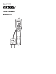
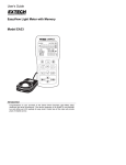
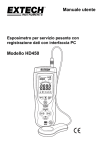
Meter Description
1.
Sensor cable plug shown connected to meter
jack
2.
USB jack for PC interface (under the flip-down
cover)
3.
LCD Display
4.
Upper Push Button set
5.
Lower Push Button set
6.
Sensor’s light collector dome
7.
Sensor housing (protective cover not shown)
8.
Power ON-OFF button
1
2
3
4
5
8
NOTE: The battery compartment, tripod mount, and
tilt stand are located on the rear of the
instrument and are not pictured
6
7
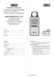
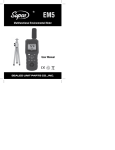
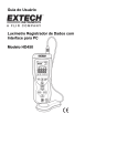
Display Description
1.
Digital measurement reading
2.
Bargraph measurement reading
3.
Auto Power OFF active icon
4.
MANU icon
5.
DATA HOLD icon
6.
RELATIVE mode icon
7.
MAXIMUM and MINIMUM reading mode
8.
PEAK HOLD mode
9.
Low Battery symbol
4
5 6 7 8
3
2
1
10. PC connection icon
11. Range units of measure
9
3
10
11
HD400 – V2.0 – 5/08
Operation
Meter Power
1.
Press the Power button
2.
If the meter does not switch on when the power button is pressed or if the low battery
icon is displayed on the LCD, replace the 9V battery
to turn the meter ON or OFF
Auto Power Off (APO)
1.
The meter is equipped with an automatic power off (APO) feature that turns the meter
off after 20 minutes of inactivity
2.
To defeat the APO feature, press and hold the APO button. While holding down the
APO button, press the RANGE button to switch off the circular APO symbol on the
upper left-hand corner of the LCD. Repeat this step to re-activate the APO feature.
The APO icon will reappear.
Unit of Measure
Press the UNITS button to change the unit of measure from Lux to Fc or from Fc to Lux
Range Selection
Press the RANGE button to select the measurement range. There are four (range)
selections for each unit of measure. The units display and decimal point location identify
the range selected. Refer to the Range Specifications section of this User Guide for
detailed range information.
Taking a Measurement
1.
Remove the sensor’s protective cap to expose the white sensor dome
2.
Place the sensor in a horizontal position under the source of light to be measured
3.
Read the illuminance measurement on the LCD display.
4.
The meter will display ‘OL’ when the measurement is outside of the meter’s specified
range or if the meter is set to the wrong range. Change the range by pressing the
RANGE button.
5.
Replace the protective sensor cap when the meter is not in use.
Data Hold
To freeze the LCD display, momentarily press the HOLD button. 'MANU HOLD' will appear
on the upper left-hand side of the LCD. Momentarily press the HOLD button again to return
to normal operation ('MANU HOLD' will switch off).
Peak Hold
The Peak Hold function allows the meter to capture short duration light flashes. The meter
can capture peaks down to 10µS in duration.
1.
Press the PEAK button to activate the Peak Hold feature. ‘MANU Pmax’’ will appear
on the display. Press the PEAK button again and ‘MANU Pmin’ will appear. Use
‘Pmax’ to capture positive peaks. Use ‘Pmin’ to capture negative peaks.
2.
To exit the Peak Hold mode and return to the normal operating mode, press the
PEAK button a third time.
4
HD400 – V2.0 – 5/08
Maximum (MAX) and Minimum (MIN) Reading Memory
The MAX-MIN function allows the meter to store the highest (MAX) and lowest (MIN)
readings.
1.
Press the MAX-MIN button to activate the feature. ‘MANU MAX’ will appear on the top
of the display and the meter will only display the highest reading encountered.
2.
Press the MAX-MIN button again. ‘MANU MIN’ will appear on the top of the display
and the meter will only display the lowest reading encountered.
3.
To exit this mode and return to the normal operating mode, press the MAX-MIN
button a third time.
Relative Mode
The Relative Mode function allows the user to store a reference value in the meter for
which to compare subsequent readings. For example, if the user stores a reading of 100
Lux, all subsequent readings will be displayed as actual reading minus 100.
1.
Take the measurement, and when the desired reference value is displayed, press the
REL button.
2.
‘MANU REL’ will appear at the top of the LCD display.
3.
All subsequent readings will be offset by the by an amount equal to the reference
level. For example, if the reference level is 100 Lux, all subsequent readings will
equal the actual reading plus 100 Lux.
4.
To exit the Relative Mode, press the REL button. ‘MANU REL’ will switch off
indicating that the meter has returned to the normal operating mode.
LCD Backlight
The meter is equipped with a backlight feature that lights up the LCD display.
1.
Press the backlight button
to activate the backlight
2.
Press the backlight button again to switch the backlight off. Note that the backlight will
turn off automatically after a short period of time in order to save battery energy.
3.
The backlight function uses extra battery energy. To conserve energy, use the
backlight feature sparingly.
5
HD400 – V2.0 – 5/08
USB PC Interface
Description
The HD400 meter can be connected to a PC via its USB interface. A USB cable, along with
TM
Windows software, is included with the meter. The software allows the user to view,
store, and print readings from the PC.
Note that the HD400 does not datalog readings, meaning that it does not store readings in
an internal memory; it simply displays readings on the PC as they are taken in real-time;
after which the readings can be analyzed, stored as text, or printed.
Meter to PC Connection
The supplied USB cable is used to connect the meter to a PC. Connect the smaller
connector end of the cable to the meter’s interface port (located under the tab at the lefthand side of the meter). The larger connector end of the cable connects to a PC USB port.
Program Software
The supplied software allows the user to view readings in real-time on a PC. The readings
can be analyzed, zoomed, stored, and printed. Please refer to the HELP UTILITY available
from inside the software program for detailed software instructions
6
HD400 – V2.0 – 5/08
Specifications
Range Specifications
Units
Range
Resolution
Lux
400.0
0.1
4000
1
40.00k
0.01k
400.0k
0.1k
40.00
0.01
400.0
0.1
4000
1
40.00k
0.01k
Foot candles
Accuracy
± (5% rdg + 10 digits)
± (10% rdg + 10 digits)
± (5% rdg + 10 digits)
± (10% rdg + 10 digits)
Notes:
1. Sensor Calibrated to standard incandescent lamp (color temperature: 2856K)
2. 1Fc = 10.76 Lux
General Specifications
Display
Ranging
Over range indication
Spectral response
Spectral accuracy
Cosine response
Measurement Repeatability
Display rate
Photo detector
Peak capture
Operating conditions
Storage conditions
Meter Dimensions
Detector Dimensions
Weight
Sensor lead length
Low battery indication
Power supply
4000 count LCD display with 40 segment bargraph
Four ranges, manual selection
LCD displays ‘OL’
CIE photopic
Vλ function (f’1 ≤6%)
f’2 ≤2%; Cosine corrected for angular incidence of light
±3%
Approximately 750 msec for digital and bargraph displays
Silicon photo-diode with spectral response filter
10µS minimum
o
o
Temperature: 32 to 104 F (0 to 40 C); Humidity: < 80%RH
o
o
Temperature: 14 to 140 F (-10 to 50 C); Humidity: < 80%RH
6.7 x 3.1 x 1.6" (170 x 80 x 40mm)
4.5 x 2.4 x 0.8” (115 x 60 x 20mm)
Approx. 13.7 oz. (390g) with battery
3.2’ (1m)
Battery symbol appears on the LCD
9V battery
7
HD400 – V2.0 – 5/08
Maintenance
Cleaning
The meter and its sensor can be cleaned with a damp cloth. A mild detergent may be used
but avoid solvents, abrasives, and harsh chemicals.
Battery Installation / Replacement
The battery compartment is located on the back of the meter. The compartment is easily
accessed by pressing and sliding the rear battery compartment cover off of the meter in
the direction of the molded arrow. Replace or install the 9V battery and close the battery
compartment by sliding the compartment cover back onto the meter.
You, as the end user, are legally bound (Battery ordinance) to return all used
batteries and accumulators; disposal in the household garbage is prohibited!
You can hand over your used batteries / accumulators, gratuitously, at the
collection points for our branches in your community or wherever batteries /
accumulators are sold!
Disposal
Follow the valid legal stipulations in respect of the disposal of the device at the
end of its lifecycle
Storing
When the meter is to be stored, please remove the battery and affix the sensor’s protective
cover. Avoid storing the meter in areas of extreme temperature and humidity.
Copyright © 2008 Extech Instruments Corporation (a FLIR company)
All rights reserved including the right of reproduction in whole or in part in any form.
8
HD400 – V2.0 – 5/08