1
WE6RFP027
Proceedings of PAC09, Vancouver, BC, Canada
loss, so it is simpler for now to use this system in singlestage mode. As we further increase the beam power, we
anticipate that we will begin using the scrapers.
The purpose of the RTBT collimator systems is to
protect the target from errant beams caused by extraction
kicker misfires, and because there are no adjustable
components, these collimators have been used as
originally planned since the first day of beam to target,
and with the possible exception of radiolysis issues, they
are working well.
RADIOLYSIS
The general definition of radiolysis is the dissociation
of molecules by ionizing radiation. In our case we have
the dissociation of water molecules in the cooling water
system by the ~1 GeV proton beam. All of our collimator
systems absorb the beam power in a water-cooled bed of
stainless-steel balls, and a typical path of a charged
particle hitting the collimator will include some water.
Radiolysis products include hydrogen, hydrogen peroxide,
oxygen and oxygen-containing radicals.
A gas sample taken in December 2008 from the HEBT
transverse collimator cooling water system showed
elevated levels of H2 (0.45% vs. the naturally occurring
0.0002% in air) and depressed levels of O2 (13.2% vs.
20.9% in air). The increased level of H2 is consistent with
the radiolysis process. The depressed level of O2 can be
attributed to the sampling method which introduced air,
possible recombination of hydrogen and oxygen within
the water loop, and the complicated water chemistry.
Particle tracking simulations using MCNPX [2] have
also been performed to estimate the fraction of the beam
power that is deposited in the HEBT transverse collimator
cooling water. The collimator geometry model was
developed according to design drawings, except that the
particle bed was represented by set of coincident cylinders
of steel and water in a volume ratio of about 65%/35%.
The beam source was represented by a disk source
perpendicular to the beam center line, with circular
symmetry on the plane of the disk, from radii 2.3 cm to
5.3 cm, and with the 1 GeV protons directed parallel to
the beam line axis. The energy deposition was calculated
on the basis of one incoming proton and then normalized
to the full beam intensity. This model indicates that for
2 kW of beam power absorbed by a collimator system,
~160 watts is deposited in the water.
Measurements taken in the neutron production target
deionized water cooling systems indicate that ~ 0.4 to 0.5
molecules of hydrogen are produced per 100 eV of energy
absorbed in the water. This, combined with the particle
tracking simulations for the HEBT collimators, allows an
estimate of the hydrogen gas creation to be ~0.5 – 0.7 l/h
for 2 kW absorbed by a HEBT collimator system. This
gas generation rate is comparable to that estimated for the
momentum collimator system. However, gas can be more
effectively vented from the HEBT transverse collimator
cooling water system, and to date it has not caused any
operational problems.
DESIGN OF NEW MOMENTUM
COLLIMATOR SYSTEM
The new momentum collimator system will include an
upgrade of the beam diagnostics between the carbon
scrapers and the beam dump. The initial design had just
beam loss monitors to estimate how much beam was
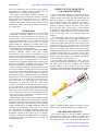
being scraped and delivered to the dump. As shown in
Fig. 1, the new design will include a beam current
monitor to directly measure the beam power being
delivered to the dump, a beam profile / position monitor
to measure the beam density and position at the entrance
to the dump, a dipole corrector to steer the beam to the
center of the dump, and some additional beam loss
monitors.
The beam dump itself is also being redesigned. Our
goal is to design and build a forced-air-cooled dump to
completely eliminate the complications (e.g. radiolysis,
resin beds, etc) that come with water cooled systems. The
conceptual design calls for removing the water-cooled
portion of the dump (thus leaving a 38 x 38 x 331 cm3
hole in the existing large stack of steel and concrete
shielding) and replacing it with an AJT graphite and AISI
A36 steel assembly. The steel is necessary since the space
available is not sufficient to fully stop a 1.3 GeV proton
beam by using only graphite. Two isometric CAD images
of the new design are shown in Figs. 2-3.
The new dump will be designed for 5 kW – twice the
rating of the old dump. Recirculated air is pumped into
the outer jacket of the new assembly. The reentrant
vacuum window is also cooled by this air. A heat
exchanger, located in the tunnel and cooled by the magnet
water cooling loop, will remove the heat from the dump.
Prof ile
BCM
BLM
BLM
BLM
Dipole
corrector
Figure 1: Momentum dump beam line upgrade. The new
dipole corrector and beam diagnostics are shown in red.
SCRAPER ELECTRONICS
The original design of the three HEBT collimator
systems had just beam loss monitors to estimate how
much beam was intercepted by the scrapers and sent to
the collimators/dump. This is an indirect and inaccurate
Accelerator Technology - Subsystems
2848
T19 - Collimation and Targetry