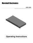
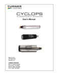
1
WET
Labs
USER’S MANUAL
SeaOWL UV-A SLC
TM
• Document Ver: 11/2015, Edition A
WET Labs
620 Applegate Street
Philomath, OR 97370
USA
Tel: +1 541 929 5650
[email protected]
[email protected]
www.wetlabs.com
Table of Contents
Section 1 Specifications .................................................................................................................... 3
1.1
1.2
1.3
1.4
Mechanical................................................................................................................................... 3
Electrical ...................................................................................................................................... 3
Communications.......................................................................................................................... 3
Optical.......................................................................................................................................... 3
Section 2 Operation and maintenance ........................................................................................... 5
2.1 Verify operation............................................................................................................................ 5
2.2 Set up for deployment.................................................................................................................. 6
Section 3 Reference ............................................................................................................................7
3.1
3.2
3.3
3.4
Delivered items............................................................................................................................ 7
Calibration.................................................................................................................................... 7
Characterization........................................................................................................................... 7
Get and install terminal program.................................................................................................. 7
3.4.1 Find sensor offset value...................................................................................................... 9
3.4.2 Common terminal program commands............................................................................... 9
3.4.3 ....................................................................................................................................... 0
3.5 Set up variable output................................................................................................................ 10
Section 4 General information ....................................................................................................... 15
4.1
4.2
4.3
4.4
Warranty..................................................................................................................................... 15
Service and support................................................................................................................... 15
Waste electrical and electronic equipment................................................................................. 15
Tera Term BSD license.............................................................................................................. 16
1
Section 1
Specifications
1.1 Mechanical
Diameter
7.57 cm
Length
5.46 cm
Depth rating
1000 m
Temperature range
-2–38 °C
Storage temperature range
-20–50 °C
Weight in air
0.399 kg
Displacement
128 ml
1.2 Electrical
Input
7–15 VDC
Current draw
81 mA
Linearity
99%
1.3 Communications
Sample rate
1 Hz
RS232 output rate
19200 baud
Output resolution
14 bit
1.4 Optical
Parameter
Wavelength EX/EM
Range, Sensitivity
Chlorophyll (Chl)
470/695 nm
0.005–250, 0.005 µg/L
Fluorescent Dissolved Organic Matter (FDOM)
370/460 nm
0.03–900, 0.03 ppb QSDE
Backscattering
700 nm
0–0.04 m-1 sr-1, 1E-06 m-1 sr-1
Crude oil limit of detection, sensitivity
< 80, 3 ppb
3
Section 2
Operation and maintenance
2.1 Verify operation
WARNING
FDOM sensors use an ultraviolet LED light source. Do not look directly at a UV LED when it is on.
It can damage the eyes. Keep products that have UV LEDs away from children, pets, and other
living organisms. Wear polycarbonate UV-resistant safety glasses to protect the eyes when a UV
LED is on.
CAUTION
Do not supply more than 15 VDC to the sensor. More than 15 VDC will cause damage.
Make sure that the sensor operates before further setup and deployment.
1. Connect the sensor to a PC that has a terminal program such as Tera Term or
HyperTerminal® installed. Refer to Get and install terminal program on page 7 for
instructions to get, install, and use a terminal program.
2. Remove the cap that protects the sensor's optical face.
3. Connect the sensor to a regulated power supply set at 12 VDC.
4. Turn on the power supply.
The sensor comes on.
5. Start the terminal program on the PC.
6. Select the appropriate "COM Port" in the terminal program.
7. Select the correct serial port settings in the terminal program.
•
•
•
•
•
baud rate: 19200
stop bits: 1
data bits: 8
flow control: none
parity: none.
Data shows in the terminal window.
8. Look at the data. The order of the data in counts, by column:
•
•
•
•
•
•
•
•
•
•
•
•
•
•
column 1: serial number of the sensor
column 2: chlorophyll LED forward voltage
column 3: chlorophyll low gain stage
column 4: chlorophyll high gain stage
column 5: chlorophyll reported
column 6: bb LED forward voltage
column 7: bb low gain stage
column 8: bb high gain stage
column 9: bb reported
column 10: FDOM LED #1 forward voltage
column 11: FDOM LED #2 forward voltage
column 12: FDOM low gain stage
column 13: FDOM high gain stage
column 14: FDOM reported
5
Operation and maintenance
9. To stop the data, select File, then Disconnect (Tera Term).
The data stops.
10. To close the program, select File, then Exit.
2.2 Set up for deployment
1. Refer to the previous section to make sure that the sensor operates correctly.
2. If necessary, remove the protective cap from the sensor.
3. Use an external power supply to supply power to the sensor for deployment.
6
Section 3
Reference
3.1 Delivered items
•
•
•
•
the sensor
a lock collar (not applicable for SLC)
a plastic protective cover for the optical face
the CD, with:
•
•
this user manual
the characterization/calibration page for the sensor.
3.2 Calibration
The manufacturer calibrates all scattering sensors to make sure that the data that is
collected meets the sensor's specifications. This information is on the sensor-specific
calibration page that comes with the sensor.
3.3 Characterization
The manufacturer uses a fluorescent material to characterize all fluorescence sensors to
make sure that the data that is collected meets the specifications of the sensor. This
information is on the sensor-specific characterization page that comes with the sensor.
3.4 Get and install terminal program
Get and install a terminal communications program to communicate between the PC and
the sensor. The steps below refer to Tera Term, an open-source terminal emulator
program, but the set up and protocols are similar for other terminal communications
programs.
1. Do the steps on the web site www.ayera.com/teraterm/download.cfm to get the
software.
2.
3.
4.
5.
a. Enter the required information on the web site.
b. Select "Save As" to save the software to a user-selected location on the PC.
c. Right-click on the .zip file and select "Extract all..."
Go to the extracted files and double-click on the ttermpro.exe file.
Push Run.
Push OK in the Tera Term: New connection window.
In the Tera Term Web 3.1 - COMx VT window, go to Setup, then Serial port...
• Port: user-selected COM x
• Baud rate: 19200
• Data: 8 bit
• Parity: none
• Stop: 1 bit
• Flow control: none
• Transmit delay, msec/char: 2
• Transmit delay, 50 msec/line
6. Push OK.
7. To view commands as they are entered, go to the Setup menu, then Terminal... and
put a check in the box next to "Local echo."
8. To save this setup, go to the Setup menu, then Save setup....
7
Reference
9. Enter a new "File name," or push Save to save the default "teraterm.ini" setup file
name.
10. Connect the sensor to a power supply set at 12 VDC and PC.
Refer to Verify operation on page 5 for details.
11. Make sure that the terminal program is open.
12. Turn the power supply on.
13. Enter 5 exclamation points (! ! ! ! !) to put the sensor in an operational mode.
The software shows 14 columns of data.
14. Enter ! ! ! ! ! to stop the sensor.
The menu of the sensor shows below the collected data.
• ser: serial number of the sensor
• ver: version of installed firmware
• ave: the number of measurements that are averaged to make up one row of data.
• seq: the manufacturer-set sequence in which data is output.
• rat: baud rate
15. Enter $par to see the settings that are saved in the sensor.
16. Enter $run to start the sensor.
The sensor collects and shows data.
17. Find the offset, or dark counts value of the sensor for data correction.
8
Reference
3.4.1 Find sensor offset value
Use the power supply that the sensor will use for deployment to find the offset value of
the sensor output. It is possible that the offset given by the manufacturer is different
because the sensor is very sensitive in terms of both input and output.
1. Cover the detectors on the optical face of the sensor with Scotch 33™ electrical tape.
Make sure that the tape does not cover any part of the LED optical bore holes.
2. If necessary, connect the sensor to the PC and power supply and start the terminal
program.
3. Turn the power supply on.
4. Enter $run, then push Enter to start the sensor operation. Let the sensor operate for
approximately 60 seconds.
5. Enter ! ! ! ! ! to stop the sensor.
6. Calculate the average each of column 4, 8, then 13.
These averages are the offset ("dark counts") values to use for chlorophyll,
scattering, and FDOM.
7. Save these values to use when the data from a deployment is processed.
8. Remove the electrical tape from the optical face of the sensor.
9. Use a lint-free wipe and isopropyl alcohol to gently clean any remaining adhesive
from the optical face.
The sensor is ready to deploy.
3.4.2 Common terminal program commands
Command
Parameters
Description
!!!!!
none
Stops the data collected by the sensor. Lets the user to enter setup values.
If the sensor is in a low-power mode, turn the power supply off for one minute, then turn the
power on and push the "!" key 5 or more times.
$ave
1–255
The number of measurements that make up each row of collected data.
$mnu
—
Prints the menu of setup values to the PC screen.
$pkt
0–65535
Sets the number of rows of data that are collected between the specified time intervals.
9
Reference
Command
Parameters
Description
$rls
none
Gets the settings from the flash memory.
$run
—
Uses the current setup values to operate.
$sto
—
Saves the desired setup values to the flash memory.
Single-parameter sensors—Fluorometer and NTU only
$asv
1
2
Sets the sensor's analog scaling value.
1 = the analog data collected covers the bottom quarter of the data range.
4
2 = the analog data collected covers half of the data range.
4 = the analog data collected covers the entire data range.
$m1d
0 to 65535
Parameter 1, dark count value to calculate the data collected in engineering units.
$m1s
float
Parameter 1, slope value to calculate the data collected in engineering units.
$m2d
0 to 65535
Parameter 2, dark count value to calculate the data collected in engineering units.
$m2s
float
Parameter 2, slope value to calculate the data collected in engineering units.
$m3d
0 to 65535
Parameter 3, dark count value to calculate the data collected in engineering units.
$m3s
float
Parameter 3, slope value to calculate the data collected in engineering units.
$man
1 = enable
0 = disable
Enables or disables manual start time. The sensor starts at a programmed wake time when
enabled. This is automatically enabled if the user enters a manual start time.
$mst
24-hour time
Enables or disables a pre-programmed start time. This allows all sensors on a system to be
synchronized to collect data.
$met
—
Prints metadata that describes the data that is collected. Field 1 is the data. Field 2 is the field
tag. Field 3 is the field name. Field 4 is used for units where appropriate.
$rat
2400 to
230400
Baud rate for communication. An invalid baud rate will default to 19200. It will show as
19201 so the user knows the software defaulted to this value.
$rfd
—
Loads the original manufacturer's setup.
$seq
0 to 3
Selects one of the pre-defined sequences to use to collect data.
$osd
0–3
Shows the output sequence for the selected value. These values agree with the meta data
shown with $mdl.
$ose
0–3
Starts the output sequence entry mode for the selected value. Enter data by line number:
$nn<space>value<enter> where nn is the field number and value is the related output field that
shows in that field. Start the sequence input with the delimiter $00 and end it with $99.
$par
—
Shows the timing and conversion parameters.
3.5 Set up variable output
The user can make and store up to four different custom output strings in the sensor. The
definition of each output string is stored as a sequence from 0–3. The default from the
manufacturer is sequence 3. The manufacturer recommends that the user does not
change this sequence. The user can change the output string from sequences 0–2.
NOTICE
If the user changes the output string it is not possible for the manufacturer to make an analysis of
sensor performance and the data that is collected by the sensor.
10
Reference
Table 1 Variable output fields
Value
Output
0
serial number
1
date, MM/DD/YY
2
time, HH:MM:SS
3
dummy date, 99/99/99
4
dummy time, 99:99:99
5
reference value 1
6
measurement 1 raw counts
7
measurement 1 engineering output 1.3E
8
reference value 2
9
measurement 2 raw counts
10
measurement 2 engineering output 1.3E
11
reference value 3
12
measurement 3 raw counts
13
measurement 3 engineering output 1.3E
14
internal thermistor counts
15
external thermistor counts
16
pressure sensor counts
17
supply voltage 2.2f
18
numeric part of serial number
19
cSlope1 1.3E, slope for engineering calculation
20
cSlope2 1.3E, slope for engineering calculation
21
cSlope3 1.3E, slope for engineering calculation
22
cleanValue1, dark counts for engineering calculation
23
cleanValue2, dark counts for engineering calculation
24
cleanValue3, dark counts for engineering calculation
41
forward voltage counts for channel 1 LED
42
forward voltage counts for channel 2 LED
43
forward voltage counts for channel 3 LED #1
44
forward voltage counts for channel 3 LED #2
240
printf tab
241
putchar 0x09 (tab)
255
printf/n (carriage return line feed)
11
Reference
Manufacturer-set Sequence 3
Manufacturer-set Sequence 3 output format
The output columns in the image above are wrapped if there is not sufficient space on a
PC screen.
1. Start a spreadsheet program such as Microsoft Excel®.
2. Make a spreadsheet as in the example below.
$0se
1
sequence number (must come first)
$0
240
start print (must follow $ose))
$1
1
column 1 output = date (first column of output)
$2
2
column 2 output = time
$3
5
column 3 output = reference counts for channel 1
$4
6
column 4 output = measured raw counts for channel 1
$5
8
column 5 output = reference counts for channel 2
$6
9
column 6 output = measured raw counts for channel 2
$7
11
column 7 output = reference counts for channel 3
$8
12
column 8 output = measured raw counts for channel 3
$9
14
column 9 output = counts for the internal thermistor
$10
255
end print (required value)
$99
end sequence input (must follow "end print")
$osd
display (show) the sequence (must follow $99)
3. Make sure that the sensor is on and in communication with the terminal program.
12
Reference
4. If necessary, start the terminal program.
5. Enter the values to set up the serial port:
6. Push OK.
7. Select the sequence made in Excel and copy (Ctrl-C) it.
8. Make sure that the cursor is in the terminal program and that the sensor is not in
operation. and
9. Select Paste from the Edit menu.
10. Type $sto to store the new sequence in the sensor.
11. Type $seq 1 to change the output of the sensor to the new sequence.
12. type $run to see the output format of the data that is collected by the sensor.
13
Section 4
General information
Revised editions of this user manual are on the manufacturer's website.
4.1 Warranty
This sensor is warranted against defects in materials and workmanship for one year from
the date of purchase. The warranty is void if the manufacturer finds the sensor was
abused or neglected beyond the normal wear and tear of deployment.
4.2 Service and support
The manufacturer recommends that sensors be sent back to the factory annually to be
cleaned, calibrated, and for standard maintenance.
Refer to the website for FAQs and technical notes, or contact the manufacturer for
support at:
[email protected]
Do the steps below to send a sensor back to the manufacturer.
1. Contact the manufacturer for a Return Merchandise Authorization (RMA).
Note: The manufacturer is not responsible for damage to the sensor during return shipment.
2. Remove all anti-fouling treatment from the sensor before sending it back to the
manufacturer.
Note: The manufacturer will not accept sensors that have been treated with anti-fouling
compounds for service or repair. This includes tri-butyl tin, marine anti-fouling paint, ablative
coatings, etc.
3. Use the sensor's original ruggedized shipping case to send the sensor back to the
manufacturer.
4. Write the RMA number on the outside of the shipping case and on the packing list.
5. Use 3rd-day air to ship the sensor back to the manufacturer. Do not use ground
shipping.
6. The manufacturer will supply all replacement parts and labor and pay to send the
sensor back to the user via 3rd-day air shipping.
4.3 Waste electrical and electronic equipment
Electrical equipment that is marked with this symbol may not be disposed of in European public
disposal systems. In conformity with EU Directive 2002/96/EC, European electrical equipment
users must return old or end-of-life equipment to the manufacturer for disposal at no charge to
the user. To recycle, please contact the manufacturer for instructions on how to return end-oflife equipment, manufacturer-supplied electrical accessories, and auxiliary items for proper
disposal.
15
General information
4.4 Tera Term BSD license
Tera Term is used under a BSD open source license.
16
WET Labs, Inc.
620 Applegate Street
Philomath, OR 97370 U.S.A.
Tel. (541) 929-5650
[email protected]
[email protected]
www.wetlabs.com
©
WET Labs, Inc. , 2015. All rights reserved. Printed in U.S.A.
**