1
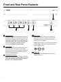
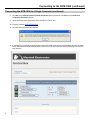
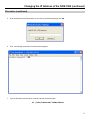
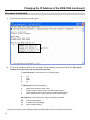
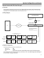
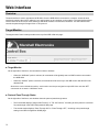
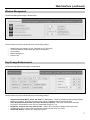
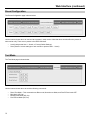
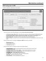
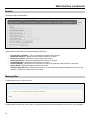
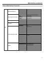
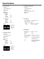
Marshall Electronics
NCB-1004
Network Control Box for IMD Monitors
Operating Instructions
Contents
Product Overview.................................................................................................................................................................. 4
Features ................................................................................................................................................................................. 4
Installation and Initial Setup ................................................................................................................................................ 5
Unpacking.............................................................................................................................................................................................. 5
Installation ............................................................................................................................................................................................. 5
Power-On Procedure............................................................................................................................................................................. 5
Front and Rear Panel Features ............................................................................................................................................ 6
RS-422 Outputs..................................................................................................................................................................................... 6
Control Input .......................................................................................................................................................................................... 6
RJ-45 Network Inteface ......................................................................................................................................................................... 6
Power Input ........................................................................................................................................................................................... 6
Power LED ............................................................................................................................................................................................ 6
Connecting to the NCB-1004................................................................................................................................................ 7
Overview................................................................................................................................................................................................ 7
Connecting the NCB-1004 to a Single Computer .................................................................................................................................. 7
Connecting the NCB-1004 to an Local Area Network............................................................................................................................ 9
Changing the IP Address of the NCB-1004 ...................................................................................................................... 10
Overview.............................................................................................................................................................................................. 10
Required Software............................................................................................................................................................................... 10
Procedure ............................................................................................................................................................................................ 10
System Configuration ......................................................................................................................................................... 13
Overview.............................................................................................................................................................................................. 13
Basic Remote Control of IMD Monitors................................................................................................................................................ 13
Overview......................................................................................................................................................................................... 13
Wiring Diagram ............................................................................................................................................................................... 13
Monitor Configuration...................................................................................................................................................................... 13
Remote Control with Image Video Pass-Through................................................................................................................................ 14
Overview......................................................................................................................................................................................... 14
Wiring Diagram ............................................................................................................................................................................... 14
Monitor Configuration...................................................................................................................................................................... 14
Remote Control with TSL Pass-Through ............................................................................................................................................. 15
Overview......................................................................................................................................................................................... 15
Wiring Diagram ............................................................................................................................................................................... 15
Monitor Configuration...................................................................................................................................................................... 15
Web Interface....................................................................................................................................................................... 16
Overview.............................................................................................................................................................................................. 16
Target Monitor ..................................................................................................................................................................................... 16
Window Management .......................................................................................................................................................................... 17
Key & Image Enhancement ................................................................................................................................................................. 17
Preset Configuration............................................................................................................................................................................ 18
Test Mode............................................................................................................................................................................................ 18
OSD Configuration & IMD.................................................................................................................................................................... 19
System................................................................................................................................................................................................. 20
Message Box....................................................................................................................................................................................... 20
Table of Web Interface Commands ..................................................................................................................................................... 21
Specifications ...................................................................................................................................................................... 22
Warranty............................................................................................................................................................................... 23
3
Product Overview
The NCB-1004 Network Control box is a comprehensive remote control solution for Marshall’s IMD (In-Monitor Display)
line of monitors. The NCB-1004 offers complete control of each monitor's menu settings and adjustments such as
contrast, color, curtain color, aspect ratio, and more. The NCB-1004 can control up to 256 monitors individually by ID#, or
up to 512 monitors simultaneously on a global scale. The NCB-1004 also enables the use of third party UMD controllers
such as Image Video or TSL, while maintaining remote control of the monitor’s settings and adjustments. The NCB-1004
is operated with a web interface via a standard TCP/IP network connection. No special application or additional software
is needed other than a standard web browser.
Features
■ Full Remote Control
The NCB-1004 offers complete control of all monitor settings and adjustments, such as brightness, color, contrast,
aspect ratio, screen markers, curtain color, IMD text, etc.
■ Control Entire Video Walls or Individual Monitors
The NCB-1004 can send global commands to affect all monitors in a video wall, or individual commands to affect
single monitors identified by ID#.
■ Support for Third Party UMD Protocols
The NCB-1004 accepts and transmits Image Video or TSL v4.0 protocol commands, while maintaining full remote
control of the monitors settings and adjustments.
■ No Additional Software Needed
As the NCB-1004 is operated with a built-in web interface via a standard TCP/IP network, no special application or
additional software is needed other than a standard web browser.
4
Installation and Power-On
■ Unpacking
Carefully unpack the NCB-1004 and verify that the following items are included:
• NCB-1004 Network Control Box
• V-PS12-5V-1 Power Supply with 2-Pin Twist Lock Connector
• Operating Instructions
Inspect the unit for any physical damage that may have occurred during shipping. Should there be any damage,
immediately contact Marshall Electronics at (800) 800-6608. If you are not located within the continental United States,
call +1 (310) 333-0606.
■ Installation
The NCB-1004 can be mounted in any standard EIA 19” equipment rack. If additional equipment is installed directly
above and below the NCB-1004 in a rack, adequate ventilation of the rack is required to prevent overheating.
Rack ears on
either side
■ Power-On Procedure
Plug the V-PS12-5V-1 power supply into an AC power source (100-240 V @ 50/60 Hz). Attach the 2-pin twist lock
connector to the back of the unit. The NCB-1004 will automatically turn ‘ON’ when power is supplied.
NOTE THAT THE NCB-1004 TAKES ABOUT 3 MINUTES AFTER POWER ON BEFORE IT IS FUNCTIONAL.
WAIT 3 MINUTES AFTER POWER ON BEFORE ACCESSING THE NCB-1004 VIA A NETWORK CONNECTION.
5
Front and Rear Panel Features
RS-422 Outputs
The RS-422 outputs send MEI protocol commands
to Marshall’s IMD line of monitors. Each output has
exactly the same signal. Up to 128 screens can be
connected to each output. These output ports also
pass Image Video or TSL v4.0 protocol commands
from the Control Input, embedded in the MEI
protocol. See Page 22 for specifications.
Control Input
The RS-422 Control Input receives Image Video or
TSL v4.0 protocol commands from an external
controller. These commands are then embedded in
MEI protocol and sent to the IMD monitors. See
page 22 for specifications.
RJ-45 Network Interface
The RJ-45 network interface is used to connect the
NCB-1004 to a standard TCP/IP network. The NCB1004 is operated via an embedded web interface.
See page 7 for configuration details.
6
Power Input
Connect the 12VDC input to the 2-Pin twist lock
power input connector. Note that the NCB-1004
takes about 3 minutes to start up after power on,
before the unit is functional.
IMPORTANT: If using a power source other than the
included power supply, be sure that the polarity of
the DC input is correct:
Power LED
The Power LED illuminates green when power is
supplied to the unit.
Connecting to the NCB-1004
Overview
The NCB-1004 can be operated by any computer with a web browser, via a TCP/IP network connection. No additional
software is needed. The NCB-1004 may be connected directly to a single computer, or connected to a local area network
and accessed by multiple computers. The NCB-1004 is shipped with the default IP address 192.168.0.233.
The following procedures describe the two ways to connect to the NCB-1004.
Connecting the NCB-1004 to a Single Computer
To use the NCB-1004 for the first time, you will most likely need to connect the NCB-1004 directly to a single computer.
After this connection is made, you can change the unit’s IP address to be suitable for your network. (See the next section
“Changing the IP Address.”
1. Connect the NCB-1004 to a Windows-based computer using a standard ethernet cable. In general, a
standard “straight” ethernet cable should be used. If the PC’s ethernet jack is not auto-switching, it
may be necessary to use a cross-over cable.
2. Supply power to the NCB-1004 with the included power supply.
3. In Windows, open the Network Connections control panel. (Start > Control Panel > Network Connections)
4. A Local Area Connection should be listed. Right-Click on Local Area Connection, and select Properties.
5. Scroll down the list in the Local Area Connection Properties, click on Internet Protocol (TCP/IP), and click the
Properties button.
6. Enter the information as shown in the picture below:
7. Note that the last number in the IP address in the picture above is 232, rather than 233.
7
Connecting to the NCB-1004 (continued)
Connecting the NCB-1004 to a Single Computer (continued)
8. Click OK in the Internet Protocol (TCP/IP) Properties window, and then click Close in the Local Area
Connection Properties window.
9. Open any web browser application (Internet Explorer, Firefox, etc.)
10. Enter the address http://192.168.0.233/
11. Click OK if the following dialog appears:
12. If successfully connected, the web interface of the NCB-1004 will be shown in the browser windows as shown
below. Make sure the NCB-1004 has been powered on for at least 3 minutes before attempting to access the
web interface.
8
Connecting to the NCB-1004 (continued)
Connecting the NCB-1004 to a Local Area Network
If the network portion of the unit’s IP address (first three numbers) matches your network, the NCB-1004 can be
connected to a local area network and accessed from any computer on the network. The unit’s IP address must also be
available on the network and reserved for the NCB-1004.
1. Connect the NCB-1004 to the network, using a standard ethernet cable:
Ethernet
cable*
Ethernet
cable
PC
Network
NCB-1004
* In general, a standard “straight” ethernet cable should be used. If the network hub’s
ethernet jack is not auto-switching, it may be necessary to use a cross-over cable.
2. Using any computer connected to the network, enter the unit’s IP address in a web browser to access the
NCB-1004 web interface.
3. If successfully connected, the web interface of the NCB-1004 will be shown in the browser windows as shown
below:
9
Changing the IP Address of the NCB-1004
Overview
The NCB-1004 is shipped with a default IP address of 192.168.0.233. This IP address can be changed via the network
connection. Note that the existing IP address must be known to make this change. If the existing IP address is
unknown, please contact Marshall Electronics for assistance.
Required Software
The following procedure requires Tera Term software for Windows, or a similar SSH tool. Tera Term is free software
available on the internet at the following location:
http://www.ayera.com/teraterm/
Procedure
1. Connect the NCB-1004 to your network or directly to your Windows-based PC, with a standard ethernet patch
cable. (When connecting the NCB-1004 directly to a computer, do not use a crossover cable.)
2. Verify connection of the NCB-1004 by loading the web interface in a browser window, at the current IP address.
3. Run the Tera Term software, and connect to the NCB via SSH at its existing IP address. Use the setting shown in
the picture below:
4. At the username prompt shown below, login as root:
10
Changing the IP Address of the NCB-1004 (continued)
Procedure (continued)
5. At the password prompt shown below, do not enter a password and simply click OK:
6. Then, the following command line interface should appear:
7. Type the following command at the command prompt, and press enter:
vi /etc/network/interfaces
11
Changing the IP Address of the NCB-1004 (continued)
Procedure (continued)
8. The following file information should appear:
9. This file must be edited to save the new IP address. Use the following commands to edit the file. Edit only the
numbers. Do not press the enter key after each command.
To move the cursor, use arrow keys or the following keys:
h
l
j
k
left
right
down
up
To edit the text, use the following keys:
x
r
i
a
delete single character under cursor
replace single character under cursor with single character
insert characters before cursor (press esc when finished typing)
insert characters after cursor (press esc when finished typing)
Save the file and exit the file editor using the following commands:
ZZ
:q!
:w
exit and save changes
exit without saving changes
save file without exiting
10. Be sure to note the new IP address. Reboot the NCB-1004 for the new IP address to take effect.
12
System Configuration
Overview
The NCB-1004 can be used in three different system configurations. The following diagrams show the different
configurations:
Basic Remote Control of IMD Monitors
■ Overview
Use the following configuration for basic remote control of Marshall IMD series monitors. This setup allows remote
control of all features in the on-screen menu of each IMD monitor.
■ Wiring Diagram
Use the following configuration for basic remote control of Marshall IMD series monitors.
PC
Network
Ethernet Cable to
Network Connection
on NCB-1004
Connect monitors to RS-422 Outputs on
Marshal IMD Monitors. Use up to 4 RS-422
outputs on NCB-1004.
Use 6P6C Modular Cable, wired pin-to-pin.
Use second RS-422 jack on
each monitor to daisy-chain
multiple monitors.
Marshall
IMD
Marshall
IMD
Marshall
IMD
Marshall
IMD
Marshall
IMD
Marshall
IMD
Marshall
IMD
Marshall
IMD
Marshall
IMD
Marshall
IMD
Marshall
IMD
Marshall
IMD
Connect up to 128
IMD screens per RS422 output
■ Monitor Configuration
The following settings are required on each IMD monitor:
IMD Protocol:
IMD Baud Rate:
ID#:
MEI
57600
Each monitor must have a unique ID# for remote control of individual monitors.
13
System Configuration (continued)
Remote Control with Image Video Pass-Through
■ Overview
Use the following configuration for basic remote control of Marshall IMD series monitors, while also passing through
Image Video protocol. This setup allows remote control of the IMD monitor, and pass-through of Image Video text and
tally commands from an Image Video TSI-1000 or other Image Video protocol source.
■ Wiring Diagram
Image Video TSI-1000 Tally Controller
(Or other Image Video Protocol Source)
Ethernet Cable to
Network Connection
on NCB-1004
PC
NCB-1004
Network
Connect monitors to RS-422 Outputs on
Marshal IMD Monitors. Use up to 4 RS-422
outputs on NCB-1004.
Use 6P6C Modular Cable, wired pin-to-pin.
Use second RS-422 jack on each monitor to
daisy-chain multiple monitors.
Marshall
IMD
Marshall
IMD
Marshall
IMD
Marshall
IMD
Marshall
IMD
Marshall
IMD
Marshall
IMD
Marshall
IMD
Marshall
IMD
Marshall
IMD
Marshall
IMD
Marshall
IMD
Connect up to 128
IMD screens per RS422 output
■ Monitor Configuration
The following settings are required on each IMD monitor:
IMD Protocol:
MEI-Image Video
IMD Baud Rate:
57600
ID#:
Each monitor’s ID# will be set automatically by Image Video controller.
IMD Name (S/N):
Each monitor must have a unique string in this field.
In this configuration, Pass-Through must be set to “ON” and to “Image Video” in the OSD Configuration & IMD
Page of the web interface. See page 19 for details.
14
System Configuration (continued)
Remote Control with TSL Pass-Through
■ Overview
Use the following configuration for basic remote control of Marshall IMD series monitors, while also passing through
TSL v4.0 protocol. This setup allows remote control of the IMD monitor along with pass-through of TSL text and tally
commands from a TSL Tally Man controller or other TSL protocol source.
■ Wiring Diagram
TSL Tally Man Controller
(Or other TSL Protocol Source)
From UMD Port on TSL Tally
Man Controller to TSL to MEI
adapter. Use standard
ethernet cable.
TSL to MEI adapter
(RJ-45 to RJ-11)
From adapter to Control Input
on NCB-1004. Use 6P6C
Modular Cable, wired pin-to-pin.
NCB-1004
Network
PC
Connect monitors to RS-422 Outputs on
Marshal IMD Monitors. Use up to 4 RS-422
outputs on NCB-1004.
Use 6P6C Modular Cable, wired pin-to-pin.
Use second RS-422 jack on each monitor to
daisy-chain multiple monitors.
Marshall
IMD
Marshall
IMD
Marshall
IMD
Marshall
IMD
Marshall
IMD
Marshall
IMD
Marshall
IMD
Marshall
IMD
Marshall
IMD
Marshall
IMD
Marshall
IMD
Marshall
IMD
Connect up to 128
IMD screens per RS422 output
■ Monitor Configuration
The following settings are required on each IMD monitor:
IMD Protocol:
IMD Baud Rate:
ID#:
MEI
57600
Each monitor must have a unique ID# for remote control of individual monitors.
In this configuration, Pass-Through must be set to “ON” and to “TSL” in the OSD Configuration & IMD Page of
the web interface. See page 19 for details.
15
Web Interface
Overview
The web interface is used to operate the NCB-1004. Once the NCB-1004 is connected to a network, access the web
interface by entering the units IP address in any web browser on any computer on the network. The web interface allows
remote control of all on-screen menu features of individual monitors or all monitors connected. The web interface also
controls the pass-through of Image Video or TSL protocol.
Target Monitor
The target monitor frame is always visible at the top of the NCB-1004 web page:
■ Target Monitor
On the right side of the frame, choose which monitors to address:
o
When the “All/Global” option is selected, all commands will be globally sent to all IMD monitors connected to
the NCB-1004.
o
When the “Address” option is selected, all commands will be sent only to the IMD monitor with the ID# in the
adjacent field.
Note that to control individual monitors, each monitor must be pre-assigned a unique ID#. Also note that GET
commands do not work in “All/Global” mode.
■ Protocol Pass-Through Status
On the right side of the frame, two windows show the protocol pass-through status:
16
o
The first window displays “Image Video Protocol” or “TSL 4.0 Protocol,” according to which protocol is selected
for pass-through in the OSD Configuration & IMD page.
o
The second window displays “Pass-Through: ON” or “Pass-Through: OFF,” according to the pass-through
setting in the OSD Configuration & IMD page.
Web Interface (continued)
Window Management
The Window Management page is shown below:
Use the buttons and menus shown above for the following settings:
o
o
o
o
o
Aspect Ratio (4:3, Scaled 4:3, 16:9, Centered 16:9 / Full Screen)
On-Screen Markers (Aspect Ratio and Safe Area Markers)
Center Marker
Marker Background
Curtain Color
Key & Image Enhancement
The Key & Image Enhancement page is shown below:
Use the buttons and menus shown above for the following settings:
o
o
o
o
Keypad Commands (Menu, Select, Up, Down, F1, F2, Power) – These commands simulate pressing keypad
buttons on a monitor. The entire on-screen menu can be navigated using this commands alone.
Color, Brightness and Contrast (Increment, Decrement, Default) – Use these commands to manually
increment or decrement the value of the corresponding control by 1 unit.
Brightness, Contrast and Color Value (0-100) – Use the SET command to assign a fixed value to the
corresponding control. Use the GET command to read the current value of a control
ColorTemp Setting – Set the color temperature preset
17
Web Interface (continued)
Preset Configuration
The Preset Configuration page is shown below:
Use the buttons shown above to load and save presets in each monitor. Note that these controls affect the presets in
each monitor only. There are no presets in the NCB-1004 itself.
o
o
Load (Load presets User1 – User6, or Factory Default Settings)
Save (Save the current settings on each monitor to presets User1 – User6)
Test Mode
The Test Mode page is shown below:
Use the buttons shown above to send the following commands:
o
o
o
o
18
Reset Test Mode – This command turns Blue mode, Monochrome Mode, and PixelToPixel mode OFF.
Blue Mode (Off, On)
Monochrome Mode (Off, On)
PixelToPixel Mode (Off, On)
Web Interface (continued)
OSD Configuration & IMD
The OSD Configuration & IMD page is shown below:
Use the first section of the OSD & IMD page to set the protocol pass-through settings:
o
o
o
o
Set Protocol (Image Video, TSL) – Select the protocol type to be passed through the NCB-1004. Note that
this option must be set according to the protocol that is applied to the Control In input on the NCB-1004.
Pass-Through (On, Off) – Enable or disable the pass-through of Image Video or TSL protocol.
Read Protocol Type – Refresh the Protocol Type display in the Target Monitor page.
Read TSL Status – Read the TSL error status. Results are displayed in the Message Box at the bottom of the
page.
Use the left-hand section of the page to configure the OSD with following commands:
o
o
o
o
IMD State (Off, On)
Status Display (Off, On)
Timecode (Off, LTC, VITC)
Audio Monitor (Off, On)
Use the left-hand section of the page to configure the In-Monitor Display:
o
o
o
o
o
o
o
o
o
Show IMD Address – This command displays the current of each monitor on each screen.
Set IMD Intensity (0-100)
Send IMD Alignment (Left, Center, Right) – Set the fixed string alignment of a monitor.
Send IMD Color (Red, Green, Yellow/Amber) – Set the fixed string color of a monitor.
Send IMD String – Set the fixed string in a monitor.
Send IMD Name – Set the IMD Name (S/N) of a monitor.
Get IMD Name – Get the IMD Name (S/N) of the selected monitor.
Show IMD – Show the fixed string on a monitor.
Show IMD Name – Show the IMD Name on a monitor.
19
Web Interface (continued)
System
The System page is shown below:
Use the buttons shown above to send the following commands:
o
o
o
o
o
o
o
o
Ping (Healthy, Unhealthy) – Test a command and response with a monitor.
Get Software Version – Reads the main software version of a monitor.
Get Protocol Version – Reads the protocol version of a monitor.
Get Keypad Version – Reads the keypad software version of a monitor
Get Model Number – Reads the model number of a monitor.
Protocol Standby – Set monitor into “serial ignore” mode, for programming other monitors on same bus
System Reset – Resets the system software on a monitor
Set Power State (Off, On) – Switches the monitor on or off. Note that although the backlight is off, power is still
supplied to monitor even when monitor is set to off.
Message Box
The Message Box frame is shown below:
The Message Box shows the current status of commands being sent and acknowledged, as well as any error messages.
20
Web Interface (continued)
Table of Web Interface Commands
Window Management
Aspect Ratio
Set Marker
Set Center
Set Background
Set Curtain Color
Menu Controls
Color
Key & Image Enhancement
Preset Configuration
Test Mode
Main
OSD Configuration & IMD
System
Brightness
Contrast
Color Temp
Load
Save
Reset Test Mode
Blue Only
Monochrome
Pixel-to-Pixel
Set Protocol
Pass-Through
Protocol Type
TSL Status
IMD State
Status Display
Timecode
Audio Monitor
Show IMD Address
Set IMD Inensity
Send IMD Alignment
Send IMD Color
Send IMD String
Send IMD Name
Get IMD Name
Show IMD
Show IMD Name
Ping
Get Software Version
Get Protocol Version
Get Keypad Version
Get Model Number
Protocol Standby
System Reset
Set Power State
4:3, Scaled 4:3, 16:9, 16:9 Centered
Off, On
Off, On
Transparent, 50% Gray, Black
Blue, Red, Green, White, Black
Menu, Select, Up, Down, F1, F2 Power
Increase Value, Decrease Value, Default, Set
Value, Get Value
Increase Value, Decrease Value, Default, Set
Value, Get Value
Increase Value, Decrease Value, Default, Set
Value, Get Value
55K, 65K, 93K, Linear
Mfg, User 1, User 2, User 3, User 4, User 5, User 6
User 1, User 2, User 3, User 4, User 5, User 6
Restore Test Mode Defaults
Off, On
Off, On
Off, On
Image Video, TSL
On, Off
Verify Protocol Type
Verify TSL Status
Off, On
Off, On
Off, LTC, VITC
Off, On
Display Address On-Screen
Set Value
Left, Center, Right
Red, Green, Yellow/Amber
Send String
Send Name
Get Name
Display IMD String On-Screem
Display IMD Name On-Screen
Healthy, Unhealthy
Display Software Version
Display Protocol Version
Display Keypad Version
Display Model Number
Enable Protocol Standby
Enable System Reset
Off, On
21
Specifications
■ CONTROL INPUT
■ NETWORK CONNECTION
Connector
1 x RJ12 (Modular 6P6C)
Connector
1 x RJ45 (Modular 8P8C)
Physical Layer
RS-422
Physical Layer
10BASE-T or 100BASE-T Ethernet
Data Protocols
Image Video:
Start Bits
Data Bits
Parity
Stop Bits
Baud Rate
Data Protocol
TCP/IP
1
7
Even
1
38400
TSL v4.0 Protocol:
Start Bits
Data Bits
Parity
Stop Bits
Baud Rate
1
8
Even
1
38400
Pinout
Pin No.
1
2
3
4
5
6
■ ELECTRICAL
Power Consumption
Voltage Requirement
3.0A @ 12VDC (36 W)
12 VDC
V-PS12-5V-1 Power Supply:
Input
100V-240V, 1.5A, 50-60Hz
Output
12VDC, 5A, 60W Max
Signal
N/C
Ground
Rx+
RxN/C
N/C
■ MECHANICAL
■ MONITOR OUTPUTS
Connectors
4 x RJ12 (Modular 6P6C)
Physical Layer
RS-422
Data Protocol
MEI
Start Bits
Data Bits
Parity
Stop Bits
Baud Rate
Pinout
Pin No.
1
2
3
4
5
6
22
Signal
RxGround
Tx+
TxN/C
Rx+
1
8
None
1
57600
Dimensions (w x h x d): 18.96" x 1.72" x 8.37”
Rack Height:
1RU
Weight:
5.5 lbs
Operating Temperature
Storage Temperature
32°F to 120°F (0°C to 50 °C)
-4°F to120°F (-20°C to 50°C)
Compliance
Œ, FCC-Class A, ANSI-63.4
(Certificates on file)
RoHs
Do not dispose. Return to
Manufacturer or Authorized
Recycle Facility.
Specifications (continued)
Warranty
Marshall Electronics warranties to the first consumer that this NCB-1004 LCD monitor will, under normal use, be free from
defects in workmanship and materials, when received in its original container, for a period of one year from the purchase
date. This warranty is extended to the first consumer only, and proof of purchase is necessary to honor the warranty. If
there is no proof of purchase provided with a warranty claim, Marshall Electronics reserves the right not to honor the
warranty set forth above. Therefore, labor and parts may be charged to the consumer. This warranty does not apply to the
product exterior or cosmetics. Misuse, abnormal handling, alterations or modifications in design or construction void this
warranty. It is considered normal for a minimal amount of pixels, not to exceed three, to fail on the periphery of the display
active viewing area. Marshall Electronics reserves the option to refuse service for display pixel failure if deemed
unobtrusive to effective use of the monitor by our technicians. No sales personnel of the seller or any other person is
authorized to make any warranties other than those described above, or to extend the duration of any warranties on
behalf of Marshall Electronics, beyond the time period described above. Due to constant effort to improve products and
product features, specifications may change without notice.
V1.2
Marshall Electronics, Inc.
1910 East Maple Ave.
El Segundo, CA 90245
Tel: (800) 800-6608 / (310) 333-0606 • Fax: 310-333-0688
www.LCDRacks.com • [email protected]