1
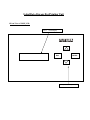
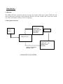
User’s Manual [(LDSP_LCD_99_2)]
Of
Label Data Storage for Printing
(LDSP_LCD_99)
By
Futura Apsol Pvt. Ltd.
1212/B/2, Apte Road
Shivajinagar,
Pune 411 004.
Telefax: 020- 25531832.
www.futuras.com
[email protected]
Software Version: LDSP_LCD_99_2.0 (12/12/13)
Label Data Storage For Printing Unit. (LDSP_LCD_99)
Packing List
1. Label Data Storage For Printing (LDSP_LCD_99) - 1 No.
2. This User’s Manual- 1 No.
3. Interfacing Cable for PC (rs232) (9 pin m - 9pin f)
4. Trigger Cable (9 pin f – other end open)
5. Cable for serial printing 1 to 1 (9 pin m - 9pin m)
6. Cable for serial printing cross (9 pin m - 9pin m)
7. A CD containing software for serial Communication with LDSP_LCD_10- 1 no.
8. LDSP_LCD_99 serial number ……………………….
INDEX
1. Front view of LDSP
2. Introduction.
2.1 Function
2.2 Description of system
2.3 Technical Specifications
2.4 General Features:
3. Installation
A] Create label file, download in LDSP, and print.
B] Down load date and time.
4 Operations
4.1 State Diagram
4.2 Menus and submenus
4.3 Keys and meaning
4.4 Meanings of various displays
4.5 Interfacing with Pc
4.6 Interfacing with Printer.
4.7 Interfacing with Barcode scanner.
4.8 Interfacing with Yc checker.
4.9 Downloading Label Data:
4.10 Downloading Date and Time:
5. Description of menus.
6. Details of terminal software.
Label Data Storage For Printing Unit
1 Front View of LDSP_LCD:
16*2
LCD Display
ESC
ENTER
4 keys sealed keyboard.
2 Introduction:2.1 Function:
This LDSP_LCD_99 is specially developed for storage and sending of label data to printer. LDSP will send
data to printer after every trigger. Along with label data, user can select variables such as date, time, month,
year, week, serial number, operator code, etc for printing.
2.2 Description of System:
POTENTIAL
FREE TRIGGER
OR SERIAL
TRIGGER
230 A.C.
(Power
Supply)
230 V A.C.
LDSP_LCD_99
PARALLEL OR
SERIAL PORT
PRINTER
SERIAL OR PARALLEL
PRINTER CABLE
ONLINE SET UP OF SYSTEM.
2.3 Technical Specifications:
1. Power Supply--- 0 ~ 230 AC, 50HZ ± 10%
2. Communication Protocols –
RS-232: Start bit-1, Stop bit-1, Handshaking-None, Baud Rate –selectable (1200, 2400,
4800, 9600, 19200). Parity – selectable (no parity or even parity).
Parallel: 8 data bits, 1 strobe, 1 busy. 25 pin D type to 36 pin centronics interface.
3. User Interface :
a) 4 key keyboard:
Up key--------Increment key.
Down Key---Decrement key.
Enter Key----Accept command.
Esc Key------Previous Menu.
b) 16 character *2 LCD display for visual interface.
4. Mechanical Dimension--- 200 * 120 * 90 mm, ABS body
2.4 General Features:
1) LDSP_LCD_99 is specially developed for data storage and send data to printer after triggering.
2) PC interface will be through RS232 serial protocol.
3) Maximum 99 different label data of 2 KB each can be stored.
4) User interface is with four keys and 16*2 LCD display.
5) Printer interface is through 25 pin D type connector for parallel port printer and
9 pin D type (F) sub for serial printer.
6) Can be interfaced to any printer having parallel port or serial port.
7) Variable data such as date, time, week, serial no, operator codes, shift times, incremented serial
No Part no, and lot no can be generated through LDSP for printing.
8) Variable captured from serial trigger can be printed on label
9) Two serial ports are available one for input one for out put.
3 Installation:Installation procedure of LDSP.
A] Create label file, download in LDSP, and print.
1) Design label on PC using label design software provided with label printer. Print this label
by connecting PC to printer.
2) Open this prn file to note pad and add # at the start and at the end of label file.
Reference:-Demo label file (example) given with in the CD.
3) Connect printer to LDSP through printer cable. Power on printer and let him take ready to
print status.
4) Connect LDSP to PC’s serial port through standard modem cable (9 pin m -9pin f ) and
download label file in to LDSP. Refer operation section for downloading.
5) After successful downloading of label data demo label print will come.
6) For different variables such as date time serial no etc. required by user, modify label file as
Reference: - Appendix 1.
7) Now select “waiting for trigger status” of LDSP to make it ready to accept trigger from
your triggering unit.
Made appropriate trigger connections via trigger cable provided with LDSP.
B] Download date and time.
1) Connect LDSP to PC serial port through standard modem cable (9 pin m -9pin f) and
download label file in to LDSP.
2) Refer operation section for downloading data and time in to LDSP. Also refer date and
time example given with CD.
C] Enter Lot no or Select default lot no.
Not available in this version.
4 Operation:4.1 State Diagram: (This is the common menu only for key reference updates in this menu are
available in concurrent appendix)
"Futura Apsol Pvt Ltd"
"Ldsp Version xx"
Enter Key
Accept Command
Esc Key
Previous Menu
Up Key
Increment Key
Down Key
Decrement Key
"
" represents displays of LDSP_LCD
"Label Data xx"
Containts in boxes represents functions
Displays previous selected location
"Receive trigger ?"
enter key
up/down key
"Waiting for trigger?"
"Set Up?"
Set up
Menus
Ldsp will wait for
trigger
"Select Label Data?"
"Pc to label Data?"
"Pc to Date and time?" "Operator codes?"
Selection
of label
location
Label Data
Reception
Mode
"Selected"
"Receiving"
"Receiving"
Waiting for data
from pc
Waiting for data
from pc
Date and Time
Reception
Mode
Operator code
Reception Mode
"Lot No?"
Lot no Menu
"change serial no?" "select cheker type?"
Not Available in
this version
"Operator code 1"
Waiting for data from barcode
code scannar 2 times
"Trial?"
"PP?"
"4 Digit Lot no?"
Select
Trial as
lot no
Select
Trial as
lot no
Enter 4 digit
lot no & select
it
Key board flow for operation
"8 Digit Lot no?"
Enter 8 digit
lot no & select
it
Not Available in
this version
4.2 Menus and Submenus (Menu name and keys accepted)
Receive Trigger: Enter/Up/Down
Waiting for Trigger: Esc
Setup: Up/Down/Esc/Enter
Select Label Data: Up/Down/Esc/Enter
Pc to label data: Up/Down/Esc/Enter
Pc to date and time: Up/Down/Esc/Enter
Operator codes: Up/Down/Esc/Enter
Receive compare data: Up/Down/Esc/Enter
Serial test: Up/Down/Esc/Enter.
Clear serial number: Up/Down/Esc/Enter
4.3 Keys and meanings:
Enter Key: For accepting command.
Esc Key: For Previous Menu.
Up Key : Increment key.
Down Key: Decrement key.
4.4 Meanings of various frequent displays:
1) “Receive trigger?”-- Asking LDSP to be ready for accepting trigger.
2) “Waiting for trigger”-- Indicates that LDSP is ready to accept trigger.
3) “Set up?”-- For entry in set up mode.
4) “Select Label Data? -- To select label location of your own choice.
5) “Pc to Label Data? -- To enter into label data reception mode.
6) “Pc to Date and Time?”-- To enter into date and time reception mode.
7) “Receive Operator Codes?”-- To enter in to operator code reception mode.
8) “Receiving”--Indicates LDSP_LCD is in serial reception mode.
9) “Demo Label print”-- Indicates ldsp is printing demo label print after saving label data.
10) “Printing”-- Indicates LDSP_LCD is printing label data.
11) “Selected”-- Indicates desired label location is selected.
12) “Part no empty”-- Indicates that part no is absent at current label location.
13) “Lot no empty”-- Indicates that lot no is absent at current label location.
14) “Label Data empty”-- Indicates that label data is absent at current label location.
15) “Check Key”--Indicates wrong key press.
16) “!!!Error!!!”—Indicates that error has been occurred during reception.
17) “Chk Lbl File”----Indicates that check label file transmitted, may be exceed capacity or wrong
format.
18) “Chk Srl Conn—Indicates that problem may be in serial connection, checks it.
19) “Not Available”---Indicates that feature is not available in this version.
20) “Operator Code 1”---Indicates that ready to receive first operator code.
21) “Operator Code 2”---Indicates that ready to receive second operator code.
22):“Receive Compare data?”—Asks user to send data on serial for comparison.
4.5 Interfacing with PC:-Connect standard modem cable (9 pin m -9pin f) to PC’s serial port 1 at
one end and LDSP’s serial port at another end.
4.6 Interfacing with Printer:-Connect printer cable to printer at one end (centronics) and LDSP
(25 pin D type) at printer port provided or connect serial port 2 (9 pin F) via serial cable to printer.
4.7 Interfacing with Barcode scanner: - Connect cross cable (9 pin m - 9 pin m) to ldsp at one
end and scanner at other end.
4.8 Interfacing for trigger: For physical Trigger:
Connect trigger cable (9 pin f) to ldsp at one end and connect two wires to potential free trigger
(for example relay).
For serial trigger:
Connect serial cable to trigger source and 9 pin D type sub connector i.e. serial 1.
4.9 Downloading Label data:
*--use serial port 1 for any type of communication with PC
•
Power on LDSP, enter in to set up menu, and select label location at which you want to save
the label file. Otherwise label file will be saved on previously selected label location.
•
Again enter in to “PC to label data mode’ from setup menu and wait till it displays
“receiving”.
•
Now Send label file through PC with the help of terminal software with appropriate setting
(refer section 6).
•
Cursor will start blinking as indication of reception starts.
•
After saving the data demo label print will come out.
•
For label file refer to example file given with the CD.
4.10 Downloading Data and Time:
*--use serial port 1 for any type of communication with PC
•
Enter in to “PC to data and time” menu from set up menu and wait till display
“receiving”
•
Send date and time file through terminal software with appropriate settings (refer
section6).
•
After saving new date and time will be assigned to LDSP.
•
For date and time file refer to example file given with the CD.
4.11 Receiving Operator Codes:
*--use serial port 1 for any type of communication with PC
•
Enter in to “Operator Code Reception” Menu and display will be “Receiving
Operatorcode1”
•
Scan first barcode using barcode scanner.
•
Scan second barcode using barcode scanner.
•
Both codes can be now retained up to power on.
•
You can print both the codes using variables codes.(refer appendix 1)
5 Descriptioin of menus
5.1 Receive Trigger? : In this menu LDSP is asking to enter in to receive trigger mode.
5.2 Waiting for Trigger: In this mode LDSP is waiting to accept trigger. It will not do any other
key operation unless escaped from this state through ESC key.
5.3 Select label data?: In this mode user can select desired label location.
5.4 PC to Label data: In this mode LDSP can accept label data from PC with the help of terminal
software.
5.5 Pc to Data and Time: In this mode LDSP can accept date and time from PC with the help of
terminal software.
5.6 Operator codes? : In this mode user can accept operator codes via barcode scanner.
5.7 Receive Compare data? : Comparison data reception and storing.
5.8 serial test? : This menu is reserved for “FUTURA”.
6 Details of ‘Terminal’ software screen are as follows :-use for sending data
through PC.
• Click connect
• Select proper com port
• Baud Rate, Data Bits, Parity, Start Bits, Stop Bits, and Handshaking
select according to LDSP_LCD_99 CONFIGURATION.
Note: For Barcode reception select even parity instead of no parity and let rest of the setting’s remain
unchanged.
For ex: Above configuration is for 2400 baud, 8 data bits, no parity, 2 stop bits and no handshaking.
Appendix 1
Selection of Printing Format: User can modify default label file as follows
# --- (add # at the start)
~Part number~ (*-- if want you can initialize part number otherwise remove tildes i.e.`~”)
Label Data @1@2@3@4@5@6---@6@7@8@9@A@B@C@D
# ---- (add # at the end)
@ 1- Date (dd/mm/yy)
@2- Time (hh:mm:ss)
@ 3- Week.
@4- Only month. (mm)
@ 5- Only year (yy)
@6- Serial number@6. (For initialization of serial no write zero to eight digits
Serial no, here. Serial no. more than eight digits not allowed.)
@7- Repeated serial no.
@8- Only day. (dd)
@A- Not Applicable
@B- Operator code 1.
@C- Operator code 2.
@D - Shift
From 07.15 am to 03.45 pm – Shift ‘A’.
From 03.45pm to 12.15 am – Shift ‘B’.
From 12.15 am to 07.15 am – Shift ‘C’.
@E-Incremented serial no.
@F- Not Applicable.
@G-Not Applicable.
@H-Not Applicable.
@I- Not Applicable.
@J— Not Applicable.
@K—Lot no.
Appendix 2
Date and time format
#ddmmyyhhmmss # (no blank space allowed)
E.g. # 231007164530#
Date: 23-10-2007
Time: 04pm: 45Min: 30Seconds.
Appendix 3 Modifications in Software version LDSP_LCD_10_1.4
(Applicable to LDSP_LCD_99)
•
Two separate triggers added in this version as follows(DOUBLE TRIGGER MODE)
PHY-SRL trigger: This is dual trigger mode i.e. unless and until both triggers are received label
will not be printed. In this mode of trigger sequence, first LDSP_LCD_10 will accept serial trigger
first and after that physical trigger will be accepted
SRL – PHY trigger: This is dual trigger mode i.e. unless and until both triggers are received label
will not be printed. In this mode of trigger sequence, first LDSP_LCD_10 will accept serial trigger
first and after that physical trigger will be accepted.
In both of above modes, during serial triggr reception, data is to be compared with all part
number stored in LDSP. If match occurs same part number label will be printed.
In any of above two modes LDSP will configure parallel port as a default printer port.
•
All the trigger settings are available in power on authority menu.
•
Part number in label data will be stored as follows
#
~ PART NUMBER~
NORMAL LABEL DATA
#
•
-----(MAXIMUM 14 DIGITS ALLOWED)
Shift timings are modified in this versions as follows
Shift can be printed on the label by @D
7.15 am to 3.45 pm - shift “A”.
3.45 pm to 0.15 am - shift “B”.
0.15 am to 7.45 am - shift “C”.
Appendix 4:
Modifications in Software version LDSP_LCD_10_1.6
(Applicable to LDSP_LCD_99)
•
Single serial trigger is modified in this version as follows(PART NO MATCH SETTINGS)
Part number match setting mode is added for single serial trigger. If part no match setting is on and
trigger type selected is single trigger, then serial trigger is compared with existing part number and
label will be printed
•
If part number match setting is enabled, then compare data setting will automatically disabled. And
vice versa.
•
Part number match setting will be available through authority menu.
.
Appendix 5:
Modifications in Software version LDSP_LCD_10_2.0 (Applicable to LDSP_LCD_99)
•
New variable i.e. @U is added for label printing @U followed by two characters will represents
single byte hex value.
For ex @UAA i.e. OxAA.
At every @U, following value will be sent to the printer port. I.e. in above example hex AA will be
sent to port.
Appendix 6:
Modifications in Software version LDSP_LCD_10_2.1(Applicable to LDSP_LCD_99)
•
Special variable i.e.@T has been added
•
@T@5
Year in the special format will be printed i.e.2010-F, 2011-G….2020-P.
•
@T@4
Month in special format will be printed i.e. JANUARY-A, FEBRUARY-B….DEC-L.
•
@T@8
Day in special format will be printed i.e. Date 1-A, 2-B….26-Z,27-1…31-5.
•
@D
Shift will be printed: 07.15am to 03.45pm-Shift ‘A’.
03.45pm to 12.15am –shift-B, 12.15am to 07.15am shift –‘C’.
For Ex
For the date 13/10/12, 12:00:00
Then FLMA will be printed.
Appendix 7:
Modifications in Software version LDSP_LCD_10_2.2 (Applicable to LDSP_LCD_99)
•
Serial number clearing facility has been given in set up menu.
After selection of clear serial number option in set up menu, serial number of selected label location
is cleared and next print will start from one.
•
CLEAR SERIAL NUMBER ON SHIFT CHANGE :
This setting can be enabled or disabled according to requirements.
If this setting is enabled then after changing of shift, all 25 serial numbers will be cleared
automatically.
*Special care should be taken for shift B: At every 00 am in the mid night date changes.
Shift “B” timings are 15:46 to 00:15. So during shift “B” running if LDSP is switched of and
powered on directly next night in shift “B”, between time 00:00 to 00:15, then older serial number
will be retained. Supervisor has to manually reset it for this special case.
Appendix 8:
New features for LDSP_LCD_99_1.2
•
Label location capacity is increased from 25 to 99 with 2k label size each.
•
Second serial port is added for data out. Hence serial port 1 is used for pc communications i.e
receiving label data, date and time, etc. as well as receiving serial trigger if applicable. And serial
port 2 is dedicatedly used for data out output i.e. for label printing and other customized features.
Modifications in Software version LDSP_LCD_99_2.0
Four new menus added in set up menu:
1: LOT NUMBER: lot number type can be selected such as TRIAL,PP, 4 digit and 8 digit mode.
In 4 and 8 digit mode actual lot number can be selected through key board.
Separate lot number is available for each location number.
Lot number can be printed on label By @K.
After every lot number change by user through key board, serial number of selected location will be
cleared.
2: ENTER SERIAL NUMBER: Serial number can be edited through key board in enter serial no.
Each location has its separate serial number and no of digits are initialized in label file only.
But it can be edited in between by this menu.
3: SELECT SHIFT: Shift code ‘A’,’B’,’C’,G’ are available through this menu.
User can manually change shift code as per requirement and changed shift code will last until
next edition.
If SHIFT_DATE_CLR_SERIAL_NUM is disabled in power on escape key menu then on every
Shift change by user all 99 serial numbers will be cleared.
Shift code can be printed on label by @Z.
4: OPERATOR CODE: operator code is 6 digit wide compulsory and of numeric type.
User can edit operator code as pee requirement. Operator code will remain store until next
updation.
Operator code can be printed on label by @a.
Old menus such as operator code( barcode mode), receive compare data, serial test, clear serial no
Are removed as they were of no use.
SHIFT_DATE_CLR_SERIAL_NUM: This setting is available in power on esc key menu.
ON: All 99 serial numbers will automatically cleared on date change at 00 hrs midnight.
OFF: All 99 serial numbers will be cleared on shift change manually by user.
Comparison setting is removed from power on esc key menu.
Setting limits compare from and to will compare serial barcode within the limits with stored part
number.


![User`s Manual [(ver2_0] Label Data Storage for Printing](http://vs1.manualzilla.com/store/data/005731436_1-9878257490003fe38f3b53735b78440c-150x150.png)