1
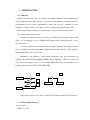
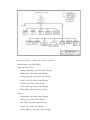
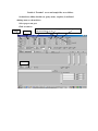
USER’S MANUAL
OF
Harness Assembly Aid / Tester with Pull
Tester
Model HAAP96.
BY
FUTURA APSOL PVT. LTD. (version 1.2)
1212/B, APTE ROAD,
SHIVAJINAGAR,
PUNE 411 004 (INDIA).
TELE- FAX: 020-2553 1832, 2552 1395
E-MAIL : [email protected].
www.futuras.com
Harness Assembly Aid / Tester Model HAAP96.
Packing List
1. Harness Assembly Aid / Tester 1 no.
2. This User’s Manual 1 no.
3. Mains cord 1 no. similar to PC mains cord.
4. Cables from tester to board / rig.
5. Cable for pull test points.
6. Futura’s Serial Cable.
7. Serial Extension Cable.
8. A Cd with necessary programmes.
Important Note : Preserve the packing sent along with the tester which is
specially designed for protection of the tester during transportation. In
case tester is to be sent back to Futura, use the same packing.
INDEX
GENERAL PRECAUTIONS.
1 : INTRODUCTION
1.1 : Function
1.2 : Specifications.
2 : DESCRIPTION OF MENUS :
2.1 : Start Assembly.
2.2 : Setup.
2.3 : Analysis.
3 : OPERATION :
3.1 : Front and Back panels.
3.2 : Display meanings and keys used.
3.3 : Power On.
3.4 : Programming.
3.5 : PC Connectivity
3.6 : Interfacing Printer
3.7 : Interfacing Relay
3.8 : Buzzer
3.9 : Assembly.
4 : CONNECTING TESTER TO RIG :
4.1 :Harness Assembly Aid to rig.
4.2 : I/O connection details.
4.3 : I/O LEDs connection details.
4.4 : Tray LEDs connection details.
4.5 : Connecting Pull Test points.
GENERAL PRECAUTIONS.
Before using the equipment read the following carefully.
Following points are to be taken care of while using the equipment. These
will protect the equipment from malfunction and any damage.
#
Any external continuity meter like buzzer, bulb or multimeter should be
strictly avoided. Use of these will damage the internal electronic delicate
components.
#
The tester is designed to work for 230V AC with ± 10% of fluctuation. If the
voltage goes below the specified voltage; the tester will not work as expected. It is
advisable to have a voltage stabilizer preferably a CVT.
#
While changing the board; removal and fitting of D type connectors on the back
side of the tester, should be done with utmost care. These connectors are polarised
and hence should not be inserted in wrong direction. There is a tendency to push
the connector hard in the tester even if polarisation is incorrect. Pushing might
damage the connectors on the tester.
# The tester has a long life and does not need much of maintenance if used
carefully. The maintenance is required for the rig or mounting board.
1 : INTRODUCTION :
1.1 : Function :
Harness Assembly Aid / Tester is to help in assembling a harness correctly including pull
test and check the same online. It improves the process and minimises assembly errors. It is
programmable by user. Once programmed, it guides the operator / assembler to insert
terminals at correct location. It also checks correct connection and displays faults online.
Pull testing facilitates checking of ‘terminal back – out’ problem with proper fixtures.
It is a microcontroller based tester.
A fixture for coupler pull test, has 4 probes (say A,B,C,D) with switches. Each switch
will be ‘on’ on applying a force of @300. Switch heights will be arranged properly so as to
get correct result.
To check, terminal after insertion, terminal is pulled manually. On pulling, switches
get ‘on’. Required force is between 900 to 1200. Hence First three switches, A,B,C should be
ON and D should be off for correct force.
Installation : In addition to other circuit connections, pull test connections are
required. It is necessary that all pull test points are in sequence. A,B,C are connected in
series. Tester has 2 inputs to sense i.e. read switches ABC and D. These are terminated on a 9
pin D type F connector as SWA, GND, SWD, GND.
D
A
GND
B
C
GND
SW D
SW A
Connections of probes are as above. On 37 pin D connector at the back side of tester.
1.2 : Technical Specifications :
Power Supply :
230V ac +/- 10%
Assembly / Testing capacity:
Number of points in a sub assembly to be tested :
96 points Harness circuit programming is by self learning. 96 LEDs for 96 points.
Number of trays (LEDs)
64 nos. LED.
Test Voltage :
TTL Logic 1 level @ 5V DC.
Test Current :
For continuity, in milliamperes.
For LED5 milliamperes.
Tester I/Os :
Points : 37 pin D F connectors, 3 nos. for 96 points 32 per connector.
Point LEDs : 50 pin centronics F connectors, 4 nos. for 96 points, 2 cables for each
LED 24 LEDs per connector.
Tray LEDs : 50 pin centronics F connectors, 4 nos. for 96 tray LEDs, 2 cables for
each LED 24 LEDs per connector.
Pull points : 2 nos. for each coupler, 9 couplers, 37 pin D F connectors, 1 no.
Terminated at back side of tester.
General
User input :
4 key touch pad sealed, keyboard viz. Enter, Up, Down, Escape.
Facility to connect PC keyboard for entering component name.
User output :
16×1 LCD display with backlit.
Buzzer audio output on Pass.
Relay no potential contact rating 230V, 5 A on Pass.
A 5mm LED on Pass.
User Interface / functional specifications.
Keys
Enter : Accept command or menu.
Up : Next command in menu or increment number.
Down : Previous command in menu or decrement number.
Escape : escape to previous menu or escape from test.
Menus and submenus : (Menu name and keys accepted)
Start Assembly : up / down / Enter.
Setup : up /down / enter.
Change component : up / down / enter / Escape.
Change data : up / down / enter / Escape.
Change label data : up / down / enter / Escape.
Label on / off : up / down / enter / Escape.
Set time : up / down / enter / Escape.
Clear counter : up / down / enter / Escape.
Time setting : up / down / enter / Escape.
Analyse? :
Display Data : up / down / enter / Escape.
Self Test : up / down / enter / Escape.
Board Test : up / down / enter / Escape.
Count? : up / down / enter / Escape.
Display Memory : up / down / enter / Escape.
Mains Supply 230V AC, +/10%, 50 Hz, with 500 mA fuse.
5V DC, 500mA supply.
Relay driver with relay
output on 3 way terminal
strip. On back panel
Buzzer driver with tone
and volume control on
back panel
Pass LED driver with
LED on front panel.
Microprocessor /
96 I/O points. On 3 nos.
37 pin D F connectors.
Microcontroller (CPU)
with EEPROM data
storage and necessary
circuitry.
16
*
1
LCD
alphanumeric Display
with Backlit. On front
panel.
96 I/O LEDs, on 4 nos. 50
pin centronics F
connectors
64 TREY LEDs on 3 nos.
50 pin centronics F
connectors.
4 keys sealed keyboard
with touch keys. On
front panel
Futura Apsol Pvt. Ltd., Pune, India.
Block Diagram of Harness Assembly Aid model HAAP96.
Drawn by GSR.
Doc No HAAP96 BD.
2 : Description of menus :
2.1 : Start Assembly :
Basis of HAAP96 is that harness assembly is done in steps. Each step involves picking up
a part either a crimped cable / cable assembly or a grommet etc. from a tray and inserting
terminals in housings at proper location i.e. points, checking it for terminal backout by
pulling.
During assembly, in a step, HAAP96 guides operator to pick parts from proper tray by
glowing corresponding LEDs. Then HAAP96 glows LED at first point where terminal is to be
inserted and blinks LED at point where next terminal is to be inserted.
If programmed for pull test, waits for pulling of terminal, sensed through fixture. It will be
sensed for the set time. If pull test is not passed, if pull is less, waits, if more, displays fault and
leaves test.
If pull test is passed, tests continuity of inserted terminal. Once correct insertion is done,
point’s LED stops blinking and HAAP96 moves on to next point in the same step. If insertion
is wrong then HAAP96 will keep displaying fault like open and short and will not go to next
step unless correct connection. While displaying faults display will be “description O xxx yyy”.
Where xxx is the starting point of the net / circuit. Meaning in described test, yyy point is open
from xxx. Similarly SHORT will be displayed. Once a step is complete HAAP96 will move on
to next step.
when all steps are over, tester can check complete subassembly again if the option is
selected on power on. By default this option is not selected. If complete subassembly is found
correct in one pass then only teser will pass the assembly.
On pass, an audio signal along with relay output and visual signal will be given out when all
steps are over. HAAP96 will start assembly of new component only when old one is removed.
2.2 : Setup:
Change component : To change selected component i.e to select component under
assembly.
Change data : Programming of new data.
New data can be programmed only from PC’s serial RS232 port.
A file in a text editor is generated in the specified format and transmitted to tester.
In the file, information required is harness name once, each step name, trey LEDs in each
step, separated by space, coupler number for pull test along with point number. Format is as
follows.
All letters should be small letters.
#
Start with #.
maruti swift
First Line is assembly name.
red net
Name of First step in sequence Maximum 8 digits..
1 2 3
Trey LEDs in first step, each separated by a space
0005 0006 0007
Step 1, net to be assembled and checked. With coupler to
be checked for pull test.
green net
4
2009 0017 8019 0020
black net
Out of four digits,
first digit indicates pull test coupler number.
0 is no pull test.
Number 1 to 9 indicates coupler number 1 to 9 for pull
test. Coupler number 2.
Point number 9 or 3.
9 10 15
0001 2003 0004 0008 2010
End with ~.
~
Label data : To load data of online label to be printed from PC.
Label on / off : To select online label printing on / off.
Set date & time : To load real time date and time from PC.
Clear counter : Clears Pass counter.
Set pull time : To set time for pull test. For how much time, tester should check pulled
point for a force of 900, settable from 1 second to 9 seconds.
Display Data : Displays stored data.
2.3 : Analysis :
Display Data : To display stored data for selected component,
Self Test : Self test, checks for all 128 I/O points open. It includes all pull test points also.
Displays result PASS if all points are open, else fail. Then glows LEDs one by one. Trey
LEDs from 1 to 96, followed by I/O LEDs from 1 to 96. Tester displays type of LED and
LED number. LEDs are to be visually checked. tester will report fault if it finds shorted
points.
Board Test : check Board facilitates making a rig / fixture and also to check fixture. When
Ground i.e. black terminal at the backside is touched at an I/O point, tester will display that
point number. All 128 points including pull points can be analysed.
3 : Operation :
3.1 : Front and Back panels:
Back Panel : Mains input socket with fuse and spare fuse, Mains power on switch, Relay
output terminal strip, tone and volume control for buzzer.
Use keyboard on front panel for functions as required. Refer to attached diagramof keypad
menus for detailed keyboard operation.
Relay : Relay will be normally off and will be on for @3 seconds on Pass. Relay output is
provided on back side on a terminal strip. Pole, NO and NC are all available for use.
Black terminal i.e. ground is to be used for board checking mode.
Connect power cord, provided with tester, which is similar to PC mains cord, to the tester
at socket provided on the back panel.
Switch on power using power on switch.
3.2 : Displayed messages, their meanings and keys to be used. :
FUTURA : Power on messaage
VER 1_2 : firmware version number.
COMPONENT NAME XX : Currently selected component name and number XX.
CHECK HARNESS? : If complete harness is to be checked after assembly.
START ASSEMBLY? : Start assembly?
SETUP? : Want to change settings? : ‘Up / down’ next menu, ‘Enter’ displays
O xx yy: Tester displays fault that xx and yy are open.
S xx yy: Tester displays fault that xx and yy are shorted.
PASS nnn : When assembly is completed and found correct and pass count nnn.
REMOVE ASSEMBLY : When assembly is completed and pass is indicate, tester
prompts to remove the present assembly.
CHECK HARNESS? : Asks if complete harness is to be checked after completing
assembly.
3.3 Power on:
Tester displays “FUTURA” for @ 2 seconds, firmware version number for @2 seconds,
last selected component name (if entered earlier) and component number for @2 seconds.
Display will be “CHECK HARNESS?” meaning after completing subassembly again
whole assembly is to be checked or not. If ‘Enter’ is pressed during this display, mode of
checking harness will be set and goes to assembly. To skip this option press ‘Esc’ key can be
pressed.
Tester displays “START ASSEMBLY?” If ‘Enter’ key is pressed here then tester starts
with step one of programme.
‘Escape’ key will skip assembly function and will be back to main menu.
3.4 : Programming : It can be done only through PCs serial RS232 port. As explained
earlier.
To load test data, label data, date etc. PC has to be interfaced with tester.
Copy software ‘terminal.exe’ from CD provided with tester to an appropriate
folder. Connect PC or Solid State Floppy to tester using Futura’s serial cable along with
serial extension cable on tester side, provided with the tester. The Y end i.e. end with 9
pin and 25 pin connectors is the PC end and other 25 pin connector end is the serial
extension cable and 9 pin end is to tester end. Y end is connected to a COM port on PC.
To load data in solid state floppy (SSF), connect Futura cable only, from PC to
SSF.
To load from PC to tester, a file has to be created. This can be generated by using
any text editor. EDD.EXE is one editor in the CD. Others like edit, notepad can be used
with care that file should be non document pure text file.
Set tester in appropriate i.e. test data or label data or date time receiving
mode.
Execute ‘terminal’ on PC,
Set baud rate (2400), data bits (8), parity (none), stop bits (2) and hand shaking
(none) as shown below.
Select proper com port.
Click on ‘connect’.
Click on ‘send file’
Select proper test data or label or date time file.
Click on open.
Selected file will be sent to tester or Solid state floppy whatever is connected.
While tester receives data, LED on controller blinks.
Test Data can be verified by using display data mode.
After receiving test data, tester displays ‘ARRANGING DATA’ and
‘SAVING’ and ‘OK’ and ‘SETUP’. After receiving label and date-time displays
‘SETUP’.
Details of ‘Terminal’ screen and sample files are as follows.
Set baud rate (2400), data bits (8), parity (none), stop bits (2) and hand
shaking (none) as shown below.
Select proper com port.
Click on connect.
Connect
COM port
Send File
baud rate (2400), data bits (8), parity (none), stop bits (2)
and hand shaking (none)
Sample Files :
Test Data :
Data starts with ‘#’ and ends with ‘~’.
# between two lines of data.
All letters in small and none in capital.
Data format :
One line comment can be written here.
#
Start with #.
maruti swift
First Line is assembly name.
red net
Name of First step in sequence Maximum 8 digits..
1 2 3
Trey LEDs in first step, each separated by a space
0005 0006 0007
Step 1, net to be assembled and checked. With coupler to
be checked for pull test.
green net
4
2009 0017 8019 0020
black net
Out of four digits,
first digit indicates pull test coupler number.
0 is no pull test.
Number 1 to 9 indicates coupler number 1 to 9 for pull
test. Coupler number 2.
Point number 9 or 3.
9 10 15
0001 2003 0004 0008 2010
End with ~.
~
Date Time :
dd = date in 2 digits
mm = month in 2 digits
yy = year in 2 digits
hr = time hours in 24 hours format in 2 digits
mn = minutes in 2 digits
ss = seconds in 2 digits
‘*’ AT THE START AND ‘~’ AT THE END.
For Example On date 3 rd January 2000 and time afternoon 3:07:09;
string will be "03012000150709"
For 2000 and onwards enter year in two digits only. Tester will
print year in four digits.
ddmmyyyyhrmnss
*03012000150709~
Label Data :
EXAMPLE OF LABEL DATA.
NOTE
‘~’ AT THE END.
BLANK LINE WILL BE PRINTED AS BLANK LINE.
AT @1 DATE WILL BE PRINTED.
AT @2 MONTH WILL BE PRINTED.
AT @3 YEAR WILL BE PRINTED.
AT @4 TIME WILL BE PRINTED.
ITEM 01234
Futura
time @4
date @1
year @3
month @2
pass.
~
3.5 : PC connectivity :
General points to remember for PC connectivity :
•
Data to be entered should be in non-document ASCII text mode using any editor / word
processor.
•
Start the data entry by a “#” character and end by a “~” character for test data and end
by “~” for label data.
•
Always use correct COM serial port.
•
Use correct settings for serial communication.
•
Always put the receiving item in receive mode first and then press “ENTER” to transmit
data.
•
Connect the cable correctly.
•
Solid State Floppy can be used to tranfer data from PC to tester. Use Futura’s
serial cable and serial extension cable.
•
PC to SSF : Y end to PC, 25 pin end to SSF. Serial extension cable not required.
•
PC to Tester : Y end to PC, 25 pin end to Serial extension cable, 9 pin end to tester.
•
SSF to Tester : Y end to SSF, 25 pin end to Serial extension cable, 9 pin end to
tester.
3.6 : Interfacing Printer :
•
A standard centronics port on DB25 F i.e. 25 pin D type female connector is provided.
It can be connected to any standard centronics printer available such as dot matrix, ink
jet, laser or bar code printers.
•
Label printing is added to print a label on every passed harness. Data to be
printed on every pass can be different for each cable number i.e. in case of CSTE,
10 different data can be stored in tester’s memory. For each cable type 1000
bytes are reserved for label data.
•
A complete label can be printed or if standard label is pre-printed then only variable
data can be printed.
•
Tester can print variables viz. Date, time, month and year of testing. To print these in
label data, at the place where date is to be printed, “@1” should be placed and for time
“@4” is to be placed etc.
•
To print special characters or bar codes, first of all printer has to be finalised. Label or
bar code printers accompany label printing software which generates an ASCII file to
be sent to printer for printing required data. Same file can be used by a little
modifications such as adding “#” characters at the start as well as end of the data and
adding character @ followed by required number, at required places for printing date
and time.
3.7 : Interfacing Relay output :
A potential free relay output with a capacity of 230V AC, 5A is provided on
a terminal strip on the back panel. This contact will be change over on every harness
passed for @ 3 seconds.
It can be used to glow a lamp or for hot stamping or for activating a
pneumatic circuit or for activating a solenoid. For inductive loads, use of snubber
circuit will prevent tester from malfunctioning.
P i.e. Pole and NO i.e. Normally Open get connected when relay is on and
pole and NC i.e. Normally Closed get open when relay is on.
3.8 : Buzzer :
On passing a harness a ringing buzzer sounds for @ 3 seconds. Buzzer’s tone and
volume can be controlled from presets at the back side.
Different tones can differentiate passed harnesses and to avoid confusion.
3.9 : Assembly :
Assembly will follow same steps as programmed. Tester will glow all tray LEDs from
which parts are to be picked up, in the first step. It also displays step number. At the same
time I/O LED corresponding to starting point say endA will glow and that of first endB will
blink. Hence parts from these trays will have to be picked up and then end A will have to be
inserted at location where LED glows. Other end/s of cable is to be inserted at endB i.e.
blinking LEDs. If it is inserted at proper location then first endB will stop blinking and next
endB LED will start blinking. At the same time all those LEDs will glow which are connected
by this net; even though the insertion is wrong. Hence identification of correct insertion is that
blinking LED stops blinking. This will continue till all I/Os in that step are connected
properly. Else display will show errors like open and short and LEDs will not stop glowing.
Once all steps are correctly assembled, tester will display pass.
Assembly : If start point is entered as ‘00’, tester will function as normal HAA without
pull test.
If start point is entered as ‘xx’, at point xx tester displays ‘FORCE < 900 xx’ i.e. pull is
less than 900 for point xx. Once switch A is on, display will be ‘FORCE >> 900’ i.e. first
switch is found OK. tester continues to check switch D for programmed time from 1second to
8 seconds. If switch D is found open, i.e. correct condition, tester starts buzzer. Buzzer will
stop after pulling is stopped and switch A is open again. If switch D is ‘on’ during this
programmed time, tester displays ‘FORCE>1200 FAIL’ and after @ 2 seconds ‘REMOVE
ASSEMBLY’.
Now
tester
is
in
continuous
checking
mode.
4 : H arness Assembly Aid connections to rig / fixture / board.
Fixture wiring involves wiring of I/O points, I/O LEDs and tray LEDs and pull
points.
For MSSL, Refer attached diagram for wiring of I/Os and LEDs
from 18 pole F connector.
Refer table folowing this section for detailed connector pin numbers.
4.1 : Wiring of 96 I/O points, Three 37 pin D F connector are provided at the back
panel of tester. 37 pin D M connector marked “points” is used. Each wire is labeled
with corresponding point number. Each point number is connected to spring type
probe / pin on assembly fixture. See table for more details.
4.2 : Wiring of 96 I/O LEDs, 4 nos. 50 pin centronics F connector are provided
at the back panel of tester. 50 pin centronics M connectors marked “I/O LEDs” are
used. Each LED requires 2 wires which are harnessed together. One wire marked
with “+5VDC” is connected to ANODE of LED and other marked with point number
is connected to CATHODE of LED of corresponding I/O point on fixture.
On connector printed pin 1 to 24 are cathodes and printed 26 to 49 are anodes.
4.3 : Wiring of 96 tray LEDs, 4 nos. 50 pin centronics F connector is provided at
the back panel of tester. 50 pin centronics M connector marked “TLEDs” is used.
Each LED requires 2 wires which are harnessed together. One wire marked with
“+5VDC” is connected to ANODE of LED and other marked with tray number is
connected to CATHODE of LED of corresponding tray on fixture.
On connector printed pin 1 to 24 are cathodes and printed 26 to 49 are anodes.
4.4 : Wiring For Pull Test points : 1 no. 37 pin D F connector marked pull test
points at the back side.
Pin1 is for 900 gms, pin 20 for 1200gms of coupler 1.
2,21 for coupler 2 and so on, for 9 such couplers.
I/O : Connector 37 pin D type M solder type on rig side. (On tester, 37 pin D F)
I/O Conne
Pin number
I/O
Conne
Pin number
I/O
Conne
Pin number
No
ctor
on connector
No
ctor
on connector
No
ctor
on connector
1
1
1
26
1
32
51
2
10
2
1
20
27
1
14
52
2
29
3
1
2
28
1
33
53
2
11
4
1
21
29
1
15
54
2
30
5
1
3
30
1
34
55
2
12
6
1
22
31
1
16
56
2
31
7
1
4
32
1
35
57
2
13
8
1
23
33
2
1
58
2
32
9
1
5
34
2
20
59
2
14
10
1
24
35
2
2
60
2
33
11
1
6
36
2
21
61
2
15
12
1
25
37
2
3
62
2
34
13
1
7
38
2
22
63
2
16
14
1
26
39
2
4
64
2
35
15
1
8
40
2
23
16
1
27
41
2
5
17
1
9
42
2
24
18
1
28
43
2
6
19
1
10
44
2
25
20
1
29
45
2
7
21
1
11
46
2
26
22
1
30
47
2
8
23
1
12
48
2
27
24
1
31
49
2
9
25
1
13
50
2
28
MSSL : Wiring or connecting of rig / fixture to tester :
Refer attached wiring diagram which gives details of wiring of I/Os, I/O LEDs,
Trey LEDs and pull points.


![User`s Manual [(LDSP_LCD_99_2)] Label Data](http://vs1.manualzilla.com/store/data/005846764_1-de86383eb41f3d06a08b51e5958ead91-150x150.png)
![User`s Manual [(ver2_0] Label Data Storage for Printing](http://vs1.manualzilla.com/store/data/005731436_1-9878257490003fe38f3b53735b78440c-150x150.png)