1
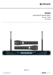
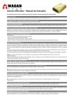
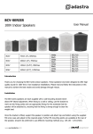
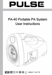
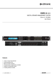
MU16 / MU26 MULTI-UHF WIRELESS SYSTEMS Item ref: 171.829, 171.830, 171.832, 171.832 User Manual Version 2.0 MU16 / MU26 User Manual Introduction Thank you for choosing the Citronic 16 channel UHF-series wireless system. This professional wireless set provides a high quality microphone with a tuneable PLL UHF radio system for ultimate wireless quality and versatility. Please read this manual before using this equipment in order to avoid damage through incorrect operation and to get the best performance from your purchase. Contents Please take care when unpacking. Inspect for any damage and ensure you have the following components… UHF wireless receiver Mains power adapter 6.3mm mono jack lead 2 x 1.5V AA battery (4 pieces for MU26H and MU26N) Rack-mounting adapters Microphone / transmitter(s) – see table below Model Stock code Microphone 1 Microphone 2 MU16H MU26H MU16N MU26N 171.829 171.832 171.830 171.833 Handheld transmitter Handheld transmitter Discreet neckband mic. + bodypack Discreet neckband mic. + bodypack Handheld transmitter Neckband mic. + bodypack Warning To prevent the risk of fire or electric shock, do not expose any of the components to rain or moisture. If liquids are spilled on any component, stop using immediately, allow unit to dry out and have checked by qualified personnel before further use. Avoid impact or heavy vibration to any components, dropping the microphone can cause capsule failure. No user serviceable parts inside transmitter or receiver - refer servicing to qualified service personnel. Safety Ensure that the correct adapter is used and that the mains voltage is as stated on the adapter. Avoid ingress of water or particles into the transmitter(s) or receiver Use alkaline or NiMH batteries in the transmitter(s) and remove if unused for long periods. Observe the correct polarity when replacing batteries Placement Keep all components out of direct sunlight and away from heat sources. Do not place heavy objects on top of the receiver or transmitter(s) If rack-mounting receivers in pairs, use the supplied rack ears and coupling brackets. Keep the transmitter(s) and receiver away from damp or dusty environments. Cleaning Use a soft cloth with a neutral detergent to clean the body of the microphone/transmitter and receiver. Lightly damp sterile wipes may be used on the microphone grille for hygiene purposes To avoid damage, do not use solvents to clean the components MU16 / MU26 User Manual Handheld Transmitter 1. 2. 3. 4. Beltpack Transmitter Windshield Backlit LCD display Slide switch – OFF/MUTE/ON Battery compartment cover 1. 2. 3. 4. 5. 6. 7. 8. UHF antenna LED indicator Sensitivity switch LINE-MIC MIC input, threaded 3.5mm jack Backlit LCD display ON/check button GAIN ADJUST rotary Battery compartment Receiver Rear Panel 1. 2. 3. 4. Antennae (detachable BNC) Power adapter input Balanced XLR output Unbalanced 6.3mm jack output 1. 2. 3. 4. 5. 6. 7. Power / IR Sync. button Channel A volume control Channel A frequency up/down Backlit LCD display IR sender Channel B frequency up/down Channel B volume control Receiver Front Panel MU16 / MU26 User Manual Operation For handheld transmitters, insert the supplied 2 x AA batteries by carefully unscrewing the base to reveal the battery compartment inside the microphone body, slide the batteries into the compartment (note: negative towards top of microphone) one behind the other and replace the compartment cover. To switch the transmitter on, move the slide switch to the first notch (MUTE) – the LCD backlight will illuminate – then move on another notch and the microphone will be switched on, showing the frequency and battery status – the backlight will go out after a few seconds. For beltpacks, squeeze down the clip in the centre of the front panel of the beltpack to unfasten the lower half, which hinges outwards to reveal the battery compartment. Position the supplied 2 x AA batteries inside (ensure + and - are the correct way round for each) and then close the battery compartment flap until clipped back into position. If using a neckband or lavalier microphone, ensure that the sensitivity switch is set to the “mic” setting (the alternative setting is for use with instruments via a jack lead and will be quieter). To activate the transmitter, press and hold the ON / CHECK button (see diagram above) until the word “ON” is displayed – this is replaced by the frequency and battery status. The backlight will go out after a few seconds, pressing the “ON / CHECK” button momentarily switches the backlight on briefly. Position the receiver within the best available line of sight to the transmitter(s) and connect the DC jack of the supplied power adapter to the receiver and the plug-top to the mains outlet. Turn microphone level(s) down on the receiver. Extend both antennae fully upwards and outwards slightly and press and hold the POWER / IR SYNC. Button for more than 2 seconds – this will switch the unit on. Note: for dual sets (with 2 transmitters), both microphones’ outputs will be mixed and fed to both balanced and unbalanced outputs. Connect the jack or XLR (optional) lead to the receiver’s audio output connector, turn down the volume of any equipment (mixer, amplifier etc.) that the signal will be fed into and then connect the jack or XLR to the equipment. Warning! - take care not to point microphones towards speakers – this can cause damaging feedback (loud whistle or howling noise) – try to point microphones away from the speaker cabinets. Tuning The receiver LCD display shows the channel number (2 separate channel numbers on dual receivers) and RF and AF level meters to indicate if Radio Frequency (RF) carrier is being received and if Audio Frequency (AF) is being heard by the receiver. To tune the transmitter(s) to the receiver, the receiver can send an Infra Red (IR) signal to the transmitter – this is called “IR Sync.”.To activate this, select the desired channel using the Frequency Up/Down buttons (see diagram above) and the channel number selected will show on the LCD display. Briefly press (do not hold) the “POWER / IR SYNC” button on the receiver and the frequency value will flash on the LCD display. For handheld units, hold the transmitter with the IR sensor (either on the end or rear of the microphone body) near to the IR sender on the UHF receiver unit (see diagram above). The display MU16 / MU26 User Manual on the handheld unit will flash until both transmitter and receiver frequencies are matched and channel numbers stop flashing. For beltpack units, open the battery compartment to reveal the IR sensor inside and hold this near to the IR sender on the UHF receiver. The display on the beltpack unit will flash until both transmitter and receiver frequencies are matched and channel numbers stop flashing. In use Gradually increase the microphone level(s) on the receiver and then increase the volume on the mixer or amplifier until the sound from the microphone can be heard through the equipment. During use, it may be useful for the reception of the microphone to be muted for a short period of time (e.g. to avoid feedback when walking across the front of a speaker or avoid handling noise when placing the microphone down momentarily or adjusting a neckband microphone). In these circumstances, it may be better to move the transmitter switch to the “MUTE” position, which maintains the radio frequency carrier signal but mutes the microphone input. When this switch is moved back to the “ON” position, the sound will be immediately restored. If the wireless system is not to be used for more than a few seconds, it is preferable to slide the transmitter switch to the “OFF” position, which mutes and deactivates the radio signal and powers down the transmitter. For beltpacks, hold the “ON / CHECK” button until the word “OFF” is displayed and release to power down. Be sure to turn down the volume of the mixer or amplifier and then switch off the receiver. Unplug signal leads from the receiver and mixer or amplifier when moving or packing away. If the system is not to be used for long periods of time, remove the batteries from the transmitter and unplug the power adapter from the receiver and the mains outlet. Retracting and/or removing the antennae can also help avoid damage when the system is not in use. MU16 / MU26 User Manual Specifications Carrier type RF carrier stability Sensitivity Audio frequency response Signal to noise ratio Audio dynamic range T.H.D. Maximum range Operating temperature UHF 863 - 865MHz (digital PLL tuning) 10PPM -105dB 40Hz – 20kHz >105dB >80dB <0.5% @ 1kHz 50m -10ºC to +50ºC Receiver Power supply Audio outputs Controls Indicators Dimensions Weight 12 - 18Vdc 500mA (mains adapter supplied) XLR (balanced), Jack (unbalanced) Power / IR SYNC, Channel volume(s), Frequency up/down Backlit LCD with Channel, RF and AF levels 45 x 200 x 175mm 905g Handheld Transmitter (MU16H, MU26H) Battery Switch RF emission Capsule type Dimensions Weight (without battery) 3Vdc (2 x AA) Power / Mute / On <10mW Dynamic – hyper-cardioid response 255 x 50mmØ 345g Beltpack Transmitter (MU16N, MU26N) Battery Switch Connector Compatible microphones RF emission Dimensions (not inc. antenna) Weight (without battery) 3Vdc (2 x AA) Power / Mute / On 3.5mm mono jack - threaded 171.855, 171.856, 171.857 <10mW 110 x 68 x 25mm 90g Neckband Microphone (MU16N, MU26N) Capsule type Power supply Connector Dimensions Weight Condenser - cardioid response 3V phantom from beltpack 3.5mm mono jack - threaded 140 x 180 x 60mm 16g MU16 / MU26 User Manual Frequency Chart Channel 1 2 3 4 5 6 7 8 Frequency (MHz) 863.35 863.45 863.55 863.65 863.75 863.85 863.95 864.15 Channel 9 10 11 12 13 14 15 16 Frequency (MHz) 864.25 864.35 864.45 864.55 864.65 864.75 864.85 864.95 Troubleshooting No backlight on UHF receiver display Receiver display is lit but no level on “RF” or “AF” meters “ “RF” meter is showing good level but no “AF” and no sound “RF” and “AF” meters showing good levels but no sound Cannot Sync frequencies via IR SYNC. Microphone output is very loud or distorted Microphone output is very low Ensure power adapter is connected to mains and working properly Ensure receiver is powered on Ensure transmitter is switched on Check that transmitter is not out of reception range Try IR frequency sync-ing to ensure frequency of transmitter is same as receiver Check that transmitter batteries are good / charged Check if transmitter switch is in “MUTE” position Check if neckband or lavalier microphone is connected to beltpack Ensure transmitter has good / charged batteries Check if there is another nearby transmitter with the same frequency – if so, switch frequencies Make sure receiver is connected to mixer / amplifier Make sure that receiver and amplifier / mixer channel volumes are turned up Place IR Sensor closer to IR Sender Make sure the correct channel frequency value is flashing on UHF receiver unit Turn down GAIN ADJUST on beltpack transmitter Turn down VOLUME on receiver Reduce Gain on mixer / amplifier Ensure that XLR output is not fed to a Line input Turn up GAIN ADJUST on beltpack transmitter Turn up VOLUME on receiver Increase Gain on mixer / amplifier Ensure that Jack output is not fed to a Mic input Ensure that Sensitivity switch is not set to Instrument level Check transmitter batteries 1622 Errors and omissions excepted. Copyright© 2012. AVSL Group Ltd. MU16 / MU26 User Manual