1
ttlvl-3Tl(0A-000-00
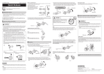
User's manual
. lf the
clamping strength is adjusted too stroDg and the quick release lever
cannot be pushed to the CLOSE position, turn the adjusting nut in a
counter<lockwise direction to reduce the clamping strength. When doing
this, do not fully release the adjuster nut. Turn it lE of a revolution, and
then tri,to push the lever to CLOSE. to set the maximum clamping
strcngth with which you can push the qulct rcleasc lever to the
CLOSE
User's manuals in other languages are available at
http://si.shimano.com
position.
:
Turn lE revolution
at a time
.
Contact the place of purchase or a bicycle dealer for information on
installation and adjustment of the products which are not found in the
user's manual. A dealer's manual for profesional and experienced bicycle
mechanics is available on our website (http://si.shimano.com).
o Do
.
Products are not.guaranteed against natural wear and deterioration from
normal use and aging,
.
For maximum performance we highly recommend Shimano lubricants and
maintenance products.
not disassemble or alter this product.
For safety, be sure to read this user's manual thoroughly
before use, and follow them for corriect use.
Before riding the bicycle, check the following items. lf any problems are
found with the following itemt contact the place of purchase or a bicycle
dealer.
o
Guidelines that rcquirc rcplacement contact the place of purchase or a
bicycle dealer,
Are the wheels fixed?
o Do
o
the wheels rotate smoothly?
Are there any abnormal noises?
WARNING
.
Check that the wheels are fastened securely before riding the bicycle. lf
the wheels arc loose in any way, ttrey may come off the bicycle and
serious injury may rcsult.
o
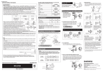
lf the quick release lever is on the same side as the
is the danger that it may interfere
with the rotor. Make sure that even if tfie quicl
release lever is tightened with your palm with all
your strength, the quick release lever does not
interfere with the rotor. lf the lever interferes
with the rotor, stop using the wheel and consult a
dealer or an agency.
roto[ there
o
re ease
After reading the user's manual carefully, keep it in a safe place for later
reference.
CAUTION
.
Quick release lever
Never fasten a wheel to a frame by rotating the
quick release lever as shown in the diagram on
the right.
Simply rotating the lever in a circular motion will
not fasten the wheel to the frame.
Detachment of the wheel as a result of improper
hub installation can result in serious bodily injury.
Note
.
o
Do not applv any lubricant to the inside of the hub, otherwise the grease
What is a Quick Release?
will come out,
It is a mechanism that uses a single quick release lever operation on the hub
to enable the wheel to be easily installed and removed.
lf the quick release lever can be easily pushed to the CLOSE position, this
means the clamping strength is insufficient. Return the quick release lever
to the position perpendicular to the bicycle frame and again turn the
adjusting nut clockwise to increase the clamping trength. Push the quick
release lever back to the CLOSE position.
Adjusting nut
Quick Release function
When the quick release lever is brought to the closed position, the lever nut
moves inward. The force of this clamps the wheel to the frame and holds the
wheel securely in place.
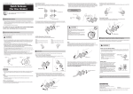
2. Open and close the quick release lever with your right hand while
gradually tightening the adjusting nut with your left hand in the clockwise
direction. Continue tightening th-e nut until you feel resistance with your
hand at thE point when the lever is p'arallel to the hub (as indicated by the
dotted position in the diagram on the right).
Adjusting nut
The clamping strength is adjusted by turning the adjusting nut. When the
nut is turned in a clockwise direction, the clamping strength increases, and
when the nut is turned in a counter-clockwise direction, the clamping
3. Grip the rear end with your fingers and use the palm of your hand to close
the quick release lever with as much strength as possible. When closed, the
quick release lever must be in the 'CLOSE' position shown below in the
diagram en the right. The side of tlie lever with the inscription "CLOSE'
must be facing away from the bicycle, and the lever should be parallel to
strength decreases.
the rear end
as
shown below in the diagram on the left.
Adjusting nut
Rear end
CLOSE
Be sure
to
use only rear end
position
Quick
Suitabte dimensions of the re'ar end
release
widths with suitable dimensions.
cannot use fork thicknesses
(Dura-Ace, 600 Ultegra: not
lever
than 5 mm.
less than 6 mm.)
less
Positioning of the quick release lever
For safety, the quick release lever should be along the bicycle frame when in
the CLOSE position.
How to fasten this quick release hub
1. Move the quick release lever to the OPEN position and set the wheel so
it
firmly touches the interior of the rear end (See sketch below).
Removing the wheel
Move the quick release lever from the CLOSE position to the OPEN position.
Loosen the adjusting nut, and then remove the wheel.
t
OK
No Good
SHIMHNO
SHIMANO AMENICAl{ CORPORATION
one Holland, ldinq c.liforoia 92618, U S,A. Phoner
SHIMAI'IO EUROPE B.V.
lndunrLweg 24,8071 Ct Nunrpeet, The Netherlands
+1-949-951-5003
sHtMAilO tNC.
Phone:
+31'341-272222
3-77 oimatsu<ho,
Sakai-ko, Sakai-shi,
oska
590{577, Japan
note: specifications are subject to change for improvement without notice. (English)
@ Jan.2012 by shimano lnc. HTR SZK
Please
-