1
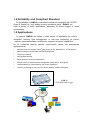
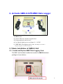
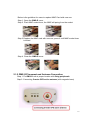
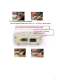
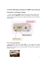
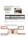
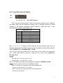
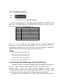
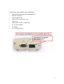
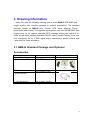
User’s Manual
GMS-G
GPS MMC Data Logger
V1.0
Federal Communications Commission (FCC) Statement
This Equipment has been tested and found to comply with the limits for a
Class B digital device, pursuant to Part 15 of the FCC rules. These limits are
designed to provide reasonable protection against harmful interference in a
residential installation. This equipment generates, uses and can radiate radio
frequency energy and, if not installed and used in accordance with the
instructions, may cause harmful interference to radio communications. However,
there is no guarantee that interference will not occur in a particular installation. If
this equipment does cause harmful interference to radio or television reception,
which can be determined by turning the equipment off and on, the user is
encouraged to try to correct the interference by one or more of the following
measures:
- Reorient or relocate the receiving antenna.
- Increase the separation between the equipment and receiver.
- Connect the equipment into an outlet on a circuit different from that to which the
receiver is connected.
- Consult the dealer or an experienced radio/TV technician for help.
Warning:
[A shielded-type power cord is required in order to meet FCC emission limits and
also to prevent interference to the nearby radio and television reception. It is
essential that only the supplied power cord be used. ]
[Use only shielded cables to connect I/O devices to this equipment.]
You are cautioned that changes or modifications not expressly approved by the
party responsible for compliance could void your authority to operate the
equipment.
[ ]: depend on EUT condition.
MultiMedia CardTM is a trademark of Infineon Technologies AG of Germany, and
is licensed to the MMCA (MultiMedia Card Association).
2
Contents
1. Introduction .................................................................. 4
1.1 General ..........................................................................................4
1.2 Features.........................................................................................5
1.3 Basic Diagram...............................................................................5
1.4 Reliability and Compliant Standard.............................................6
1.5 Applications....................................................................................6
1.6 Technical Specification .................................................................7
1.7 Software Interface (NMEA Message Sentences)......................7
2. Activate GMS-G GPS MMC Data Logger .................. 11
2.1 Basic Installa tion of G MS-G Unit .......................................... 11
2.1.1 Install and Replace MMC Data Logging Card.............................11
2.1.2 GMS-G Placement and Antenna Connection......................... 12
2.1.3 Connecting Power Supply ....................................................... 13
2.2 Three LED Status Indicators for MMC Card, Antenna
Connection, and Power Supply .......................................................14
2.2.1 Incorrect Installation................................................................ 14
2.2.2 Status Indicators Table............................................................ 15
2.3 Configurable Logging Switches.................................................15
2.3.1 Log Time Interval Switch ......................................................... 16
2.3.2 Log Message Switch............................................................... 17
2.4 Extended GPS Message Output (Optional) .............................17
3. Ordering Information ................................................... 19
3.1 GMS-G Standard Package and Optional Accessories .......19
3
1. Introduction
1.1 General
GMS-G GPS MMC (MultiMedia Card TM) data logger is the high
quality and professional tool for fleet management with efficiency and safety
concerns. With the built-in GPS engine and MMC (Multi-Media Card) up to 128
MB (default 32 MB), users can continuously and accurately record and traveling
routes in forms of date, time, longitude, latitude, speed, and satellites status.
With its configurable switches design, users can set those recording interval
and logged messages of interests. Moreover, Off-line fleet management with
these traveling information will bring users benefits performing optimal routes
planning, fuel control, personal dispatching, and trajectory monitoring.
In addition, the default NMEA-0183 logging format is convenient for users to
do post processing with 3rd party or compatible data analysis software in host
side.
4
1.2 Features
With the state-of-the-art friendly design consideration for a variety of
applications, GMS-G has the following features:
Ÿ
12 channel GPS satellite continuous tracking
Ÿ
Flexible log record interval from 3 seconds (default setting) to 68 minutes
Ÿ
Flexible log NMEA messages selection (default RMC sentence recording)
Ÿ
State-of-the-art 32 MB MMC card log data design (64 MB, 128 MB upon customer’s
inquiry) for off-line post processing applications
Ÿ
Real time monitoring with extended GPS message output via RS232 cable connection
in host side (upon customer’s inquiry)
Ÿ
Extended 1 PPS signal output feasibility (upon customer’s inquiry)
Ÿ
12~24VDC power design allows versatile vehicles installation
Ÿ
Rugged housing design mitigate violating or damage impact
1.3 Basic Diagram
With the dedicated design for off-line recording data analysis from vehicle
purpose, provides users full GMS-G package at easy operation and
installation. Please refer to the following diagram and peripherals:
5
1.4 Reliability and Compliant Standard
As for reliability of GMS-G, it has been certified and compliant with CE/FCC
Class B. Based on high quality product assurance policy, GMS-G can
meet a variety of many applications, especially for those rugged or harsh
environments.
1.5 Applications
In general, GMS-G can satisfy a wide variety of application for vehicle
navigation, tracking, fleet management, or real time monitoring. Its interior
superior hardware/software architecture supports advanced capabilities
for all customers through specific requirements. Below are summarized
applications as:
Ÿ
Real time Personal navigation with 3rd party E-map on PC, Notebook PC, or PDA platform
Ÿ
Data recordings in transportation and fleet management
Ÿ
Trajectory monitoring
Ÿ
Over speed monitoring
Ÿ
Safety protection under pre-defined area
Ÿ
Efficient tool for cost-effective fleet management, transportation, and logistics
Ÿ
Optimal platform for routes planning, fuel control, dispatching
Ÿ
Trajectory monitoring for time, Lat, Lon, speed, heading, satellites information
GMS-G
GPS MMC Data Logger
6
1.6 Technical Specification
General
MMC Support
File System
Logged data (message) format
Log Record Interval (resolution)
Power Supply
Power Consumption
Physical
Dimension (mm)
Weight
Operating Temp
Humidity
EMI/EMC
Optional extended GPS message output
GMS-G
Default: 32 MB
Optional: 64 MB, 128 MB
Version supported: v1.4, v3.0
FAT-16
NMEA-0183
Default: RMC
Optional: GGA, GLL, GSA, GSV, VTG
3 seconds (minimum) to 68 minutes
+12~ 24 VDC
Less than 2 watt (w/ antenna)
Compact and robust housing design
94.5 (W) x 136.0 (D) x 45.0 (H)
340 g
0°C to +70°C
95% R.H.
CE, FCC
Baud rate: 4800 bps
Protocol: NMEA-0183
RMC, GGA, GLL, GSA, GSV, VTG
Signal: 8 N 1
Signal Format: TX ONLY (RS232 level)
1 PPS signal output
Specifications are subject to change without notice
1.7 Software Interface (NMEA Message Sentences)
NMEA-0183 format as defined by the National Marine Electronics
Association (NMEA), Standard For Interfacing Marine Electronic Devices, Version
2.20, January 1, 1997.
Table 1 NMEA-0183 Output Messages for GMS-G
NMEA Record
GGA
GLL
GSA
GSV
RMC
VTG
Description
Global positioning system fixed data
Geographic position - latitude/longitude
GNSS DOP and active satellites
GNSS satellites in view
Recommended minimum specific GNSS data
Course over ground and ground speed
GGA--- Global Positioning System Fixed Data
Table 2 contains the values for the following example:
$GPGGA,161229.487,3723.2475,N,12158.3416,W,1,07,1.0,9.0,M, , , ,0000*18
Table 2 GGA Data Format
7
Name
Message ID
UTC Position
Latitude
N/S Indicator
Longitude
E/W Indicator
Position Fix
Indicator
Satellites Used
HDOP
MSL Altitude
Units
Geoid Separation
Units
Age of Diff. Corr.
Diff. Ref. Station ID
Checksum
<CR> <LF>
Example
$GPGGA
161229.487
3723.2475
N
12158.3416
W
1
07
1.0
9.0
M
M
Units
Description
GGA protocol header
hhmmss.sss
ddmm.mmmm
N=north or S=south
dddmm.mmmm
E=east or W=west
See Table 3
Range 0 to 12
Horizontal Dilution of Precision
meters
meters
meters
meters
second Null fields when DGPS is not used
0000
*18
End of message termination
Table 3 Position Fix Indicator
Value
0
1
2
3
Description
Fix not available or invalid
GPS SPS Mode, fix valid
Differential GPS, SPS Mode, fix
valid
GPS PPS Mode, fix valid
GLL--- Geographic Position – Latitude/Longitude
Table 4 contains the values for the following example:
$GPGLL,3723.2475,N,12158.3416,W,161229.487,A*2C
Table 4 GLL Data Format
Name
Message ID
Latitude
N/S Indicator
Longitude
E/W Indicator
UTC Position
Status
Checksum
<CR> <LF>
Example
$GPGLL
3723.2475
N
12158.3416
W
161229.487
A
*2C
Units
Description
GLL protocol header
ddmm.mmmm
N=north or S=south
dddmm.mmmm
E=east or W=west
hhmmss.sss
A=data valid or V=data not valid
End of mes
End of message termination
8
GSA---GNSS DOP and Active Satellites
Table 5 contains the values for the following example:
$GPGSA,A,3,07,02,26,27,09,04,15, , , , , ,1.8,1.0,1.5*33
Table 5 GSA Data Format
Name
Message ID
Mode 1
Mode 2
Satellite Used in
solution
Satellite Used in
solution
Satellite Used
PDOP
HDOP
VDOP
Checksum
<CR> <LF>
Example
$GPGSA
A
3
07
Units
02
Description
GSA protocol header
See Table 6
See Table 7
Sv on Channel 1
Sv on Channel 2
Sv on Channel 12
Position Dilution of Precision
Horizontal Dilution of Precision
Vertical Dilution of Precision
1.8
1.0
1.5
*33
End of message termination
Table 6 Mode 2
Value
1
2
3
Description
Fix not available
2D
3D
Table 7 Mode 1
Value
M
A
Description
Manual- forced to operate in 2D or 3D mode
Automatic-allowed to automatically switch 2D/3D
GSV---GNSS Satellites in View
Table 8 contains the values for the following example:
$GPGSV,2,1,07,07,79,048,42,02,51,062,43,26,36,256,42,27,27,138,42*71
$GPGSV,2,2,07,09,23,313,42,04,19,159,41,15,12,041,42*41
Table 8 GSV Data Format
Name
Message ID
Number of
Messages1
Message Number1
Satellites in View
Satellite ID
Elevation
Azimuth
SNR (C/No)
Satellite ID
Elevation
Azimuth
SNR (C/No)
Checksum
<CR> <LF>
Example
$GPGSV
2
1
07
07
79
048
42
27
27
138
42
*71
Units
Description
GSV protocol header
Range 1 to 3
Range 1 to 3
Channel 1 (Range 1 to 32)
Degrees
Degrees
DBHz
Degrees
Degrees
DBHz
Channel 1 (Maximum 90)
Channel 1 (True, Range 0 to 359)
Range 0 to 99, null when not tracking
Channel 4 (Range 1 to 32)
Channel 4 (Maximum 90)
Channel 4 (True, Range 0 to 359)
Range 0 to 99, null when not tracking
End of message termination
9
1. Depending on the number of satellites tracked multiple messages of GSV data
may be required.
RMC---Recommended Minimum Specific GNSS Data
Table 9 contains the values for the following example:
$GPRMC,161229.487,A,3723.2475,N,12158.3416,W,0.13,309.62,120598, ,*10
Table 9 RMC Data Format
Name
Message ID
UTC Position
Status
Latitude
N/S Indicator
Longitude
E/W Indicator
Speed Over
Ground
Course Over
Ground
Date
Magnetic
Variation
Checksum
<CR> <LF>
Example
$GPRMC
161229.487
A
3723.2475
N
12158.3416
W
0.13
Units
Description
RMC protocol header
hhmmss.sss
A=data valid or V=data not valid
ddmm.mmmm
N=north or S=south
dddmm.mmmm
E=east or W=west
309.62
degrees
True
degrees
ddmmyy
E=east or W=west (Not shown)
knots
120598
*10
End of message termination
VTG---Course Over Ground and Ground Speed
Table 10 contains the values for the following example:
$GPVTG,309.62,T, ,M,0.13,N,0.2,K*6E
Table 10 VTG Data Format
Name
Message ID
Course
Reference
Course
Reference
Speed
Units
Speed
Units
Checksum
<CR> <LF>
Example
$GPVTG
309.62
T
Units
degrees
degrees
M
0.13
N
0.2
K
*6E
knots
km/hr
Description
VTG protocol header
Measured heading
True
Measured heading
Magnetic
Measured horizontal speed
Knots
Measured horizontal speed
Kilometer per hour
End of message termination
10
2. Activate GMS-G GPS MMC Data Logger
1. GMS-G Unit
2. 5-meter GPS active antenna, magnetic base
3. Fixing peripherals (and screws)
4. Car cigarette lighter power cord input 12 ~ 24 VDC
5. 32MB MMC data logging card (64 MB, 128 MB upon customer’s
inquiry) (support version 1.4 and 3.0)
2.1 Basic Installation of GMS -G Unit
2.1.1 Install and Replace MMC Data Logging Card
The MMC card has been installed into socket for GMS-G standard
package unit (see below).
11
Below is the guideline for users to replace MMC Card with new one:
Step 1. Open the GMS-G cover.
Step 2. Push MMC socket lever, the MMC will spring from the socket
Step 3.Replace the MMC card with new one, press it until MMC socket lever
is locked
Step 4. Close the GMS-G cover
2.1.2 GMS-G Pl acement and Antenna Connection
Step 1. Fix GMS-G unit at proper location with fixing peripherals
Step 2. Connecting 5-meter GPS active antenna (with magnetic base)
12
2.1.3 Connecting Power Supply
Use Car cigarette lighter power cord (+12 ~ 24 VDC) for power supply.
13
2.2 Three LED Status Indicators for MMC Card, Antenna
Connection, and Power Supply
In the front panel of GMS-G, there are three LED status indicators that
depict the real time GMS-G status: MMC card ins tallation, GPS position data
validity status, and data writing process integrity with different colors combination
and appearance.
2.2.1 Incorrect Installation
Once the MMC card does NOT EXIST in the socket OR installed
INCORRECTLY, the color for ALL three indicators will be RED!! In this case,
please check if the MMC card is correctly installed. Also check power supply and
antenna connection.
14
2.2.2 Status Indicators Table
Below is the table to describe different real time GMS-G status.
PWR MMC GPS
Status (see Note 1)
Description
R
O
R
G
R
R
O
O
G
R
G
N
MMC card does NOT EXIST, OR not installed correctly
Valid GPS position data is NOT available yet
(Usually it should take 3 or 4 minutes to track sufficient
GPS satellites information to obtain valid position data)
Valid GPS position data is available
Writing GPS position data into MMC card (only when valid
GPS position data is available) (see Note 2)
Note 1:
The Color Abbreviation list is: R (RED), O (ORANGE), and G (GREEN)
Note 2:
Once the writing process is failed (into MMC card) at certain time of moment, the PWR status indicator will
be R (RED).
2.3 Configurable Logging Switches
Log message switch
(NMEA sentences
recording selection)
Log messages table
Log time interval
switch (minimum
resolution of 3
seconds)
Log time interval table
15
2.3.1 Log Time Interval Switch
ON
OFF
12345678
SW (DIP Switch)
The “Log time interval switch” sets the log record interval rate of interests
into MMC card with the resolution ranging from 3 seconds (minimum record
interval) to 68 minutes (maximum record interval). Users can refer to the
accompanied “Log time interval table” as:
TIME SWITCH
1
2
3
4
5
6
7
8
1
2
5
10
20
30
YMDH
MIN/SEC
SW 1, 2, 3, 4, 5, 6: These six DIP switches set the recording rate value of
interests. The actual recording rate value is the summation of those SWs with ON
status. DEFAULT is 3 seconds (SW 1, 2 ON).
SW 8: This DIP switch sets recording rate unit. While SW is set ON, it means the recording rate
unit is “minute” (MIN); while SW is set OFF, it means the unit is “second” (SEC). DEFAULT is
SEC (SW 8 OFF).
Example:
Ÿ
Recording rate – 15 seconds: SW 3, 4 ON
Ÿ
Recording rate – 3 minutes: SW 1, 2, 8 ON
SW 7: This DIP switch sets the recording file nomination. DEFAULT is ON.
Example: At the time moment of UTC time 2002/06/09 12:00:00
Ÿ
If SW 7 is set OFF: the recording file name will be 02060912.DAT
It suits to record short time, i.e. one week
Ÿ
If SW 7 is set ON: the recording file name will be 020609##.DAT
It suits to record long time.
16
2.3.2 Log Message Switch
ON
OFF
12345678
SW (DIP Switch)
The “Log message switch” sets the log record of NMEA-0183 sentences into
MMC card. The default log record is NMEA-0183 RMC sentence. Users can refer
to the accompanied “Log message table” as:
LOG SWITCH
1
2
3
4
5
6
7
8
GGA
GLL
GSA
GSV
VTG
SW 1, 2, 3, 4, 5: These five DIP switches set the recording NMEA-0183
sentences of interests when separate SW is ON. From SW 1 to SW 5, it
corresponds recording GGA, GLL, GSA, GSV, and VTG sentences separately.
NMEA-0183 sentence information can be referred to section 1.7.
Example:
Ÿ
SW 1 ON / OFF: GGA record ON / OFF
Ÿ
SW 2 ON / OFF: GLL record ON / OFF
Ÿ
SW 3 ON / OFF: GSA record ON / OFF
Ÿ
SW 4 ON / OFF: GSV record ON / OFF
Ÿ
SW 5 ON / OFF: VTG record ON / OFF
2.4 Extended GPS Message Output (Optional)
In addition to MMC card data recording and post-processing data analysis in
host side, offers extended GPS messages output via RS232 level TX
transmit signal. Users can order optional dedicated RS232 cable
(Female-Female) transmit the GPS messages (NMEA-0183) to host side. In this
case, real time monitoring with trajectory estimation becomes achievable.
Another special extended issue is 1 PPS signal output. But users should
17
consult with sales staff for more information.
Here is the summary of pin description as:
Ÿ
Baud rate: 4800 bps
Ÿ
Protocol: NMEA-0183
Ÿ
RMC, GGA, GLL, GSA, GSV, VTG
Ÿ
Signal: 8 N 1
Ÿ
Signal Format: TX ONLY (RS232 level)
Ÿ
P2: TX (Transmit Data)
Ÿ
P5: Ground
Ÿ
P9: 1 PPS signal output
18
3. Ordering Information
Users can refer the following ordering form to order GMS-G GPS MMC data
logger product with standard package or optional accessories. The standard
package consist of GMS-G unit, 5-meter GPS active antenna, Fixing
peripherals (and screws), Car cigarette lighter power cord, and 32 MB MMC data
logging card. As for optional extended GPS message output (see section 2.4),
users should order another dedicated RS232 cable (Female-Female) to do real
time monitoring. As for 1 PPS signal output requirement, please consult with
sales staff for more information.
3.1 GMS-G Standard Package and Optional
Accessories
Description
Standard package
1. GMS-G package
part number
Diagram or illustration
1000150006
Optional accessories
1. Dedicated RS232 cable
(Female-Female)
Upon customer’s inquiry
2. 1 PPS signal output
Upon customer’s inquiry
19