1
3.2.
Programming the isa card “dip-switches”
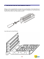
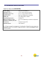
Once the card addressing procedure has been completed, it is necessary to define
the following values by programming the dip-switches:
1.
The I/O interval start value (e.g.: 0100).
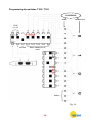
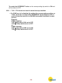
IMPORTANT: position ON = Ø (see example in fig. 14).
In this case, the following dip-switches are used:
T102 and T103 Æ COM a Æ which communicates via connector J1
T102 and T106 Æ COM b Æ which communicates via connector J2
2.
The interrupt value.
IMPORTANT: to select the interrupt, set only the corresponding dip-switches to
ON. All the other dip-switches must be set to OFF (see example in fig. 14).
In this case, the following dip-switches are used:
T101 Æ INTERRUPT CHA Æ COM a (which communicates via connector J1)
T104 Æ INTERRUPT CHB Æ COM b (which communicates via connector J2)
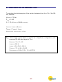
When setting the dip-switches it is important to bear in mind that each hexadecimal
digit must be converted into 4 binary digits for use in the programming procedure
illustrated in the diagram (fig. 14).
- 14 -