1
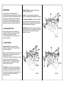
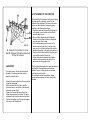
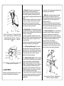
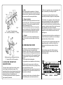
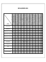
OPERATOR’S HANDBOOK
AND SPARE PART’S LIST
DISC PLOUGHS
MODELS
N2D - 28F
N3D - 28F
N4D - 28F
N5D - 28F
INDEX
RECOMMENDATIONS TO THE OWNER
CONDITIONS OF GUARANTEE
INNOVATIONS
1- EXPLANATORY NOTE
2- CONSTITUTION
3- ASSEMBLAGE
4- ATTACHMENT TO THE TRACTOR
5- TECHNICAL SPECIFICATIONS (APPROX.)
6- ADJUSTMENTS
7- WORKING
8- MAINTENANCE
9-REPLACING THE PARTS OF GREATEST WEAR
10- ORDERING SPARE PARTS
11- SECURITY REGULATIONS
RECOMMENDATIONS TO THE OWNER
CONDITIONS OF GUARANTEE
.
The decision to opt for GALUCHO was a good one.
The result of many years of
experience, under the most difficult and diverse
working circumstances, GALUCHO material gives
complete satisfaction to its many thousands of users,
both in Portugal and in over 40 countries, of different
continents, where it is already at work. We are sure
that, if used properly, and given the necessary care to
maintenance, the machine you have just acquired will
perform the efficient and economical job for which it
was designed, and which a user has the right to
expect from it. The present manual contains very
important instructions concerning set-up, tuning,
maintenance, etc., As well as diagrams and a parts
list.
Begin by reading it, attentively, in order to familiarise
yourself with the material. Then, keep it in secure
and accessible place, for future consultation.
If you still have doubts, consult the distributor who
supplied the machine, or else consult us, as it is in all
of our interests that you be satisfied with, and obtain
maximum yield from your purchase.
Recordings and technical data are indicated by name
and subject to alterations without
previous notification.
.
1- Our company guarantees all the agricultural
equipment which is manufactured for a period of two
years from the date of invoice.
1.1- This guarantee only includes the supply of
replacement parts or components which are proved
to be deficiently made or installed, and does not
cover the payment of manual labour or displacement
costs.
1.2- Any components considered by this company to
the worn out, are excluded from the guarantee.
1.3- The guarantee given by this company will not
include any parts not made by themselves, for
examples tyres, which will remain the exclusive
responsibility of their respective manufacturer, and
this decision will be communicated to the claimant
with all its consequences.
GALUCHO - Indústrias Metalomecânicas, S.A.
Apartado 4003 - E C S. João das Lampas
2706-851 S. João das Lampas - PORTUGAL
Telef.: (351) 21 960 85 00 Fax: (351) 21 960 85 85
www.galucho.pt
[email protected]
2- Reasons for immediate loss of guarantee:
2.1- Use of equipment in abnormal working
conditions, or used with tractors of different powers
than those indicated, in each different case, in our
technical literature.
2.2- The substitution of pieces or accessories for
others not made or recognised by this company.
2.3- Any repair or alteration done, during the period
of guarantee, without our knowledge or
authorisation.
3- All claims against the guarantee must be
communicated to us by the respective retail agents,
by means of a claim form. The pieces or
accessories, which are the objects of complaint,
must be sent for examination to our Technical
Services and Quality Department.
If the reasons for the complaint are confirmed and
accepted, new pieces will be supplied, or their value
credited to the customer, if already sent.
4 - The powers indicated in our catalogues and other
literature as necessary for certain equipment
of our
.
construction, may vary according to the different
types and states of
the earth, the experience of the operator, the state of
the tractor, and the adherence of the latter to the
terrain on which it is working.
5 - This company can only accept the return of
equipment to the factory, within a maximum of 15
days after the sending of the invoice, providing it has
not been used in a working situation, it is not a
model already withdrawn from production, or if it is
still part of our production range, there have been no
alterations made to the model.
6 - In compliance with regulations determined in the
Directiva Máquinas/CE (Machines Directive/CE), this
company:
6.1 - Manufactures its machines respecting the
relevant safety regulations, namely with respect to
the protection of moving parts;
6.2 - Supplies a certificate of conformity, referring to
the norms and regulations fulfilled;
6.3 - Supplies a user's manual and catalogue of
parts for each machine.
NOTE: Every Galucho dealer is obliged to supply the
eventual consumer with:
- The safety devices, fixed or detachable, relevant to
each machine;
- The certificate of conformity and the user's manual
with a catalogue of parts for each machine.
7 - We recommend the reading of our pamphlet:
“General Conditions of Sale and Payment”.
8 - For any necessary clarifications, please consult
our Commercial Services.
INNOVATIONS
GALUCHO-IND. METALOMECÂNICAS, S.A.
continually attempts to perfect its products, reserving
itself the right, at any time, to make alterations to the
design and/or to the specifications of construction
materials, and its respective components, without
incurring, as a result, the obligation to apply these
alterations to machines previously made and sold.
1- EXPLANATORY NOTE
Although all the models of the three series are
dimensionally different, the assembly, adjustment,
maintenance, etc. details are the same.
The structural differences may be checked in the
table of specifications.
Flange hub shields - pressed reversible parts to
protect the hubs against wear.
Scrapers - of highly resistant pressed steel, the
scrapers are independent and adjustable for each disc.
Furrow wheel or stabilizer - maintains the stability of
the machine whilst it is ploughing. There are various
settings and the axle is supported by adjustable taper
roller bearings protected by retainers.
Standing leg - leg fixed to the chassis to maintain the
plough up right when it is not attached to the tractor, so
that it remains in the correct position ready to be
attached to the tractor.
N3D-28F
2- CONSTITUTION
Frame or Chassis - this is a welded tubular
framework of forged steel which supports all other
parts of the disk plough.
Prop - the steel prop mechanism consists of two arms
which support its, to which is attached the upper
hydraulic arm on the tractor.
The offset bar is attached underneath the prop which
in turn permits various different setting, the
attachment for type I, II or III, depending upon the
model and what is to be attached to the 2 lower
hydraulic arms of the tractor.
Sets of discs - These consist of a disc assembly
carrier which links the frame, and turn the hub, disc
holder plate, disc and flange hub shield. The hubs
and disc holder plates made from pressed steel, and
have taper roller, sealing washer and a leak
elimination system.
N2D-28F
N4D-28F
4- ATTACHMENT TO THE TRACTOR
N5D-28F
A- Frame; B- 3.rd point bar; C- Cross
shaft; D- Scrapers; E- Depth control wheel;
F- Stay; G- Link pins
3- ASSEMBLY
If, for space reasons, the ploughs are delivered
dismantled, the following procedure must be
followed to assemble them.
- Assemble the prop mechanism with the respective
screw and linkage pins.
- Attach each disc unit to the frame using the
respective screw in central hole of disc assembly
carrier and a screw clamp.
- Tighten the 4 screws that connect the furrow
wheel to the support of the last disc. The lateral
adjustment brace should be introduced and fixed.
- Position the standing leg in its respective support
and secure it with a tension pin.
After assembling the plough and verify that everything
has been carried out correctly, connect it to the
hydraulic lifting equipment of the tractor in the same
way as any other agricultural implement, paying
attention to the following prop settings.
- The different methods of connecting the linkage bar
to the system in order to obtain a more efficient
automatic depth control.
- The two different height settings of linkage and
tension pins for a better performance, dependent
upon the make of tractor used.
- 6 or 8 holes depending upon the model, for the
lateral movement to the left or to the right of the
prop, giving 3 or 4 different settings in line with the
adjustment necessary to the gouge of the tractor, so
that the wall of the furrow opened by the first disc is
in line with the inside of the rear tyre.
- 4 holes which allow the chassis to be inclined in
relation to the furrow wheel, and which offer a
permutation of cutting angle position.
After connecting the plough to the tractor the standing
leg should be removed and place in the inverse
position. Carry out a lifting exercise to make sure
everything is as it should be.
Do not forget to connect the stabilizers, always
leaving a minimum space to allow the plough total
freedom.
5 - TECHNICAL SPECIFICATIONS (APPROX.)
DISCS
MODELS
QUANT.
WORKING
Ø
DEPTH
( " - mm)
(m)
WORKING UNDERBEAM
WIDTH
CLEARANCE
(m)
(m)
DISTANCE
BETWEEN
BODIES
(m)
WEIGHT
(kg)
REQUIRED
POWER
(hp)
N2D - 28F
2
28 - 710
0,35
0,65
0,69
0,58
365
35 - 55
N3D - 28F
3
28 - 710
0,35
0,95
0,69
0,58
475
55 - 70
N4D - 28F
4
28 - 710
0,35
1,25
0,69
0,58
595
70 - 90
N5D - 28F
5
28 - 710
0,35
1,55
0,69
0,58
715
90 - 110
6.1- Horizontal -The machine is kept transversely
horizontal trough the third point assembly by
maintaining the two lower hydraulic tractor arms the
same length. Lengthening or shortening the tractor
linkage regulates the longitudinal horizontal state of the
plough.
These two settings are considered to be correct when,
working on level ground, the plough is level with the
ground when seen from the side or from behind.
It should be remembered that the longitudinal setting
must always be done by furrow wheel.
Fig. 2
A - Disc; B - Disc carrier; C - Flange hub; D - End
cap; E - Articulation screw; F - Selection; G - Angle
of penetration hole; H - Disc arm; I - Three hole
scale for angle; of tilt regulation; J - Flange hub
shield
6.2- Ploughing depth - This is decided by the angles
of the discs with the ground, whether vertically related
penetration angle or whether related to the direction of
movement - cutting angle.
Increasing the penetration angle will help to turn the
ground over better. This reduces the penetration power
of the discs and also makes it necessary to have a
more potent tractor.
The larger the cutting angle the deeper the ploughing,
with traction increasing in the same proportion.
6.2.1- Setting the penetration angle - This must be
done separately for each disc, with the same setting
applied to each one. Loosen the link screw and move
the selection screw to the next higher hole if you wish
to lessen the angle. Make sure the 2 screws are
tightened after making any changes.
Fig. 3
A - Disc; B - Scraper; C - Scraper arm; D - Scraper support;
E - Scraper regulator; F - Fixing screws.
6- ADJUSTMENTS
Other than prop settings described in point 4, further
settings can be obtained in the following way:
6.2.2- Setting the cutting angle - Each disc assembly
carrier has three holes which allows various individual
settings. As the offset bar also permits 4 different
groups of settings, this gives a total of 12 different
settings. The individual setting of each disc should be
carried out separately so that they are equal. After
loosening the nuts of each clamp, take out the screw.
Rotating the assembly carrier, utilize one of the other
two holes, depending upon desired angle.
The group setting is done by altering the fixed position
of the frame in relation to the offset bar and is obtained
by changing the fixed position of 2 screws of the 4
existing holes.
Any alteration to the cutting angle automatically means
the altering the furrow wheel steel.
6.3- Width of cut - Altering the angle of the plough
chassis in relation to the offset bar (There are 4
different positions) gives the same number of different
cutting depths. This is the cutting angle variation
described in point 6.2.2.
The maximum cutting depth is equal to the minimum
cutting angle and vice-versa. Special attention must be
paid to ensure that the depth of the open furrow out by
the front disc is always equal to the others.
6.3.1- Clearance between discs - It is natural that the
discs became reduced in diameter though normal
wear and tear- resulting in a strip of ground left
unploughed between furrows. This can be avoided by
making the disc setting closer together as they become
worn. This process reduces the depth of cut but
improves the quality of the ploughing.
Slacken the screw clamp nuts of second and
consecutive discs. Loosen and remove the cutting
angle selection screw and advance the disc one hole.
When the holes are equal replace and tighten the
Fig. 4
A- 3.rd point bars; B- Prop; C- Adjusting holes;
D- Holes for a angle of tilt regulation
6.4- Furrow wheel or stabilizer - The furrow wheel
plays a fundamental part in the stability of the plough
in action, guiding the plough in such a way that it
does not move away from furrow. This facility is
caused by the force produced by t5he obliqueness of
the work of the discs in relation to the tractor.
The height setting is relative to the chassis and also
the inclination of ground to be ploughed. The height
must vary according to the depth of cut required,
already explained in the cutting angle and penetration
angle setting.
Turn the handle to higher or lower the wheel as
desired.
Maintaining the correct heights through wear of the
furrow wheel or discs is obtained by altering the fixed
setting in one of the three holes in yoke.
The setting for the lateral movement of the wheel,
enabling it to work at the bottom of the furrow next to
the wall, is obtained by increasing or decreasing the
length of the penetration angle setting bar, rotating it
in the respective nut.The furrow wheel is set correctly
when there is no noticeable reaction in the direction
of the tractor working on level ground.
6.5- Scrapers - These are independent for each disc
and are responsible for removing the earth from the
discs and permitting the turning over the soil an thus
covering the vegetation more efficiently. Height
settings and distances from discs can be regulated
very simply by slackening the 2 holding screws,
choosing the desired position and tightening the nuts.
It may necessary to take the scrapers off it they
become choked up because of the state of the land
or vegetation.
7- WORKING
7.1- AVERAGE WORKING PERFORMANCE
Although work performance may vary due to a
number of factors, it is useful to state the process for
determining it. It is necessary to know:
Ws - Average speed of working, in km/h;
Ww - Working width (m)
Fe - Field efficiency. This is a corrective factor which
varies for each type of work, and which is a
consequence of different determining factors, such as:
type and state of the soil being worked; configuration
and size of the land;
efficiency and effort of the operator, etc. Without too
much risk of error, we can assume an average factor of
.
Ec=0,8.
Example:
What is the average working performance of
a plough with a cutting depth of 1.55 m, working
at an average speed of 6 km/h?
Aw = WsxWwxFe Aw= 6x1,55x0,8 = 0,74 ha/h
10
10
8- MAINTENANCE
To maintain any implement in perfect working
condition, and to guarantee that it has a long and
profitable working life, avoiding the loss or premature
wearing of its components, it is essential that some
care and maintenance be invested in it, over the
following periods:
8.1- Before the start of each day
Make a thorough check of the plough, paying particular
attention to the following points:
- Ensure that all nuts and screws are tightened;
- Make certain that all moving parts - discs, flange hub
shields, scrapers and furrow wheel are in good working
order,
- Check the disc hubs for leaks.
8.2 - During Work
In case of new plough tighten all nuts at the end of the first
day.
- Lubricate the plough after every 8 hours of work
- With Grease 2, or equivalent - all the grease nipples of
the various articulations
- With oil, the remaining mobile points;
8.3- In case of prolonged stop
- Carefully wash the plough with pressurized water and
shelter it from sun and rain.
- Carry out an overhaul, retighten and replacing
whatever is necessary.
- Start the hydraulic cylinders so that the pistons are
brought in;
- Perform any necessary painting retouches, do a
general lubrication.
Following the previous procedures will assure the
ploughs, perfect work conditions for the next campaign.
Remarks:
- Always clean the grease nipples, before and after
lubrication;
- Pump as many times as necessary until clean
greases come out.
8.4- Elimination of play in the roller bearings Play
can occur in the roller bearings of the discs or the
furrow wheel. Take the following steps to avoid these
situations:
- Disc hub
- Take off the hub cap, loosening the 3 securing
screws,
- Remove the split cotter pin from the slotted nut and
rotate it until the slack disappears ,allowing the disc to
turn freely;
- Replace the split cotter pin in the slotted nut and
return the hub cap,
- Furrow wheel
- Remove the hub cap and proceed as for the discs.
A - Angle of tilt regulator screw;
B - Hole for screw insertion; C - Clamp
Fig. 6
A- Adjustment brace; B- Support of last disc;
C- Handle; D- Yoke; E- Bar regulation
9- REPLACING THE PARTS OF
GREATEST WEAR
The parts, which received the most wear, are the
discs, flange hub shields and scrapers. Their
respective duration obviously depends upon the type
of the soil they are used to plough, the conditions of
utilization and amount of maintenance out.
The following steps should be taken to replace the
parts previously mentioned.
2- Outline the quantities, codes, and designation of the
parts, as indicated by the catalogue of parts.
9.2- Flange hub shields
As these are reversible they should be turned round
once one side is worn. This is done by removing the 2
fixing screws. They should be replaced before they
become completely worn out.
It should be remembered that the lack of opportune
reversal or replacement of these flange hub shields
could mean the necessary substitution of the hubs
which is a very much more expensive exercise.
4- To facilitate the completion of orders, all demands
must be made separate from other correspondence,
and indicate the destination and the transport to be
used. In case the client has no current account with our
company, he should enclose with his order, the amount
that corresponds to the cost of his demand.
If the demand omits a preference, in terms of means of
transport, we will use that which we feel to be most
advantageous.
9.3- Scrapers
When there is no more room for adjustment due to
wear, they can be removed by simply out the fixing
screws.
5- The parts can be picked up from our warehouses, in
S. João das Lampas, or placed by us in the railway or
any other station, in Sintra or Lisbon.
10- ORDERING SPARE PARTS
6- The return of parts or equipment whose parts have
stopped being made, or which are still part of our
production line but have been altered, will not be
accepted.
We advise you, as farmers, that replacing worn out
parts at the right moment will avoid abnormal
mobilization of the machine (with the consequent loss
of money and time), and will cheapen the units of work
produced, and prolong its useful, economical life-span.
It is always better to use genuine GALUCHO parts,
because:
- They are perfectly interchangeable;
- They guarantee correct adaptation and functioning.
While they could, in some cases, be a little more
expensive in terms of initial cost, they always end up
more economical than any other.
To simplify and speed up the supply of spare parts, it is
recommended, in the consumer's own interests, that
this procedure is followed:
1- Indicate the model, series, and number written on
the identification plate, which each machine has
3- To avoid errors, written confirmation of orders
eventually transmitted by telephone is indispensable.
The identification plates GALUCHO indicate the
following specifications, which will be useful when
ordering spare parts.
- INDÚSTRIAS METALOMECÂNICAS, S. A.
DOC Nº 08.4 (MQ)
Fig. 5
9.1- Discs
With the plough slightly suspended on 3 hydraulic
points of the tractor, loosen the 4 screws, which hold
each disc in place. Remove the old disc and replace it
with a new one with the same specifications.
(Fundada por JOSÉ FRANCISCO JUSTINO)
FÁBRICA DE ALFAIA S AGRÍCOLA S
REBOQUES, CARROÇARIA S
E BA SCULANTES PARA CAMIÕES
Ano Fabr.
APARTADO 4003 - EC S. JOÃO DASLAMPAS
2706-851 S. JOÃO DASLAMPAS - PORTUGAL
Mod.
1
1-MODEL
Série
Peso (Kg)
2
2-SERIES
Nº
3
3-NUMBER
11- SECURITY REGULATIONS
.
Working with tractors and agricultural
machines requires that the operator knows what
he is doing and that much care is taken. He must
be conscious and cautious of the dangers which
imprudence can cause, not just to the agricultural
enterprises which they run. In an attempt to avoid
accidents, therefore, we advise the following
security rules:
1 - In attaching any implement to the tractor, use
only the place which the respective manufacturer
advised for the operation, verifying is carried out in
order.
.
2 - Whenever, for reasons of repair, checks, set-up
or otherwise, you need to get under the
implement, never do so without the relevant props.
3 - In activating the hydraulic system of the tractor,
first check that the implement, trailer, frontal load,
or otherwise, in movement, can not reach anyone.
4 - Never authorise the transport of passengers
on the implement, whether during work time or
on the road, equally not behind ploughs, or grass
cutters, as during their work, as stones, sticks etc.
could fly up out of the machines.
5 - The implement should never be detached while
in movement. If it has to be done, immobilizes it
well and stop the motor.
6 - Always use protective guards on transmissions
linked to the power sockets of the tractor.
7 - Use counterweights on the front or on the front
wheels, as, with implements mounted, the steering
. very light and it will have a
of the tractor will be
tendency to uplift. Double check the maintenance
during a job, manoeuvres or on the road. It could
also be necessary to mount a rear weight to the
tractor when operating with a frontal load and the
load being carried is particularly heavy.
8 - Do not forget that the dangers increase with the
incline of the terrain on which it is working or being
moved. Exercise maximum caution, paying attention
to accentuated inclinations, especially lateral ones,
which should be avoided.
9- When you work with trailers, you should never
forget to:
- Check your brakes;
- Attach the emergency brake device to the tractor;
- Plug in the electric installations;
Also remember that:
- The trailer must always brake before the tractor;
- All load, especially high load, must be well
fastened down;
- The two pins to fix down the box must be in the
right places, depending on the side which you
need to balance;
- The balancing must be light, and without jolts;
- You may only transport persons when legally
authorised to do so, when they are seated, and
with all the coverings closed.
10 - Whenever in transit on a public highway
remember that:
- On leaving an agricultural property,. or a private
road, you never have priority of entry into a public
road. All other road users, coming from the left or
right, have priority over you;
- You must respect the highway code and all signs
and light signals;
- The stabiliser switch for the two brake pedals must
be on;
- The stabilisers or the chains must be tight so that
there can be on lateral oscillation of the mounted
implements, which must only be lifted to the height
necessary to avoid contact with the ground (about
0,30 cm) or, if the tractor has a hydraulic blockage,
until this switches on;
- Speed of travel must be reduced whenever the
state or the relief of the road requires it;
If you take this advice which we give here, we hope
that you will neither have, or cause any accidents.
This is what GALUCHO wishes for, and expects
from their clients.
INSUFFICIENT DEPTH
EXAGGERATED DEPTH IN REAR FURROW
INSUFFICIENT WIGTH IN FRONT FURROW
REACTION IN THE TRACTOR DIRECTION
EXCESSIVE DEPTH
X
EXAGGERATED DEPTH IN FRONT FURROW
X
EXAGGERATED WIGTH IN FRONT FURROW
X
X
TRACTOR SKATING
X
X
X
TRACTOR RAISE
X
X
X
X
ADJUST THE TUNNING NUT
ADJUSTE THE TRACTOR
DEPTH CONTROL
X
X
ADJUST THE REVERSION
CHAIN LENTH
X
REGULATE THE SCRAPPERS
X
X
X
REGULATE THE DISCS
SHARP THE POINT BAR
X
ADJUSTE THE TRACTOR GAGE
PUT WEIGHTS IN THE
TRACTOR FRONT
REDUCE THE VELOCITY
BALAST THE MOTRICE
WHEELS
BLOCK THE DIFFERENTIAL
USE THE TRACTION CONTROL
GO DOWN THE 3 HYDRAULIC
POINTS
ARAISE THE 3 HYDRAULIC
POINTS
LOWER TRANSVERSE BAR
DECREASE THE ATACK ANGLE
INCREASE THE ATACK ANGLE
SHORTEN THE SUPERIOR
HYDRAULIC ARM
X
X
SKATING
AVANCE THE POINT BAR
X
X
DIFICULTIES IN REVERSION
X
X
PROBLEMS
EXTEND THE SUPERIOR
HYDRAULIC ARM
RECOMMENDATIONS
PRATICAL ADJUSTEMENTS ADVICES
/
01
/ 04
Data 99 / 01
/ 04
Data
Designa.
/
/
FIXED DISC PLOUGS
Serie
N2D-28F
Cod.
215140000
FU
Alter.
Verif.
ADA EM 1
9
ND
20
Desen.
Data 99
SARA
INDÚSTRIAS METALOMECÂNICAS, S.A.
S. JOÃO DAS LAMPAS - PORTUGAL
99 / 01
/ 04
Data
99 / 01
/ 04
Data
/
/
FIXED DISC PLOUGS
Serie
N3D-28F
Cod.
215220000
FU
Designa.
ADA EM 1
9
ND
20
Data
Alter.
Verif.
Desen.
SARA
INDÚSTRIAS METALOMECÂNICAS, S.A.
S. JOÃO DAS LAMPAS - PORTUGAL
99 / 01
/ 04
Data
99 / 01
/ 04
Data
/
/
FIXED DISC PLOUGS
Serie
N4D-28F
Cod.
215320000
FU
Designa.
ADA EM 1
9
ND
20
Data
Alter.
Verif.
Desen.
SARA
INDÚSTRIAS METALOMECÂNICAS, S.A.
S. JOÃO DAS LAMPAS - PORTUGAL
/
01
/ 04
Data 99 / 01
/
04 Data
/
/
FIXED DISC PLOUGS
Serie
N5D-28F
Cod.
215420000
FU
Designa.
ADA EM 1
9
ND
20
Data 99
Alter.
Verif.
Desen.
SARA
INDÚSTRIAS METALOMECÂNICAS, S.A.
S. JOÃO DAS LAMPAS - PORTUGAL
NOTES
NOTES
- INDÚSTRIAS METALOMECÂNICAS, S. A.
(Fundada por JOSÉ FRANCISCO JUSTINO)
APARTADO 4003 - EC S. JOÃO DAS LAMPAS
2706-851 S. JOÃO DAS LAMPAS - PORTUGAL
TELEF.:(351) 21 960 85 00 FAX: (351) 21 960 85 85
www.galucho.pt
[email protected]
0608.N-DF.3