1
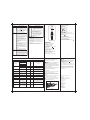
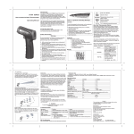
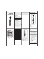
Overview
UT351/352
SOUND LEVEL METER
OPERATING MANUAL
Sound Level Meter Model UT351 and UT352 (hereafter
referred to as “the Meter”) is a stable, safe and reliable
sound level meter. The Meter is suitable to use in noise
control, quality control, health care and all different kind of
environmental noise testing. For example: factory, road,
family, musical instrument and all kind of places which
need noise testing.
Soft cloth and mild detergent should be used to clean
the surface of the Meter when servicing. No abrasive
and solvent should be used to prevent the surface of the
Meter from corrosion, damage and accident.
Constantly check the battery as it may leak when it has
been using for some time, replace the battery as soon
as leaking appears. A leaking battery will damage the
Meter.
International Electrical Symbols
Conforms to Standards of European Union
The Meter Structure (see figure 1)
Unpacking Inspection
Open the package case and take out the Meter. Check
the following items carefully to see any missing or
damaged part:
Item
1
Description
English Operating Manual
Qty
1 piece
2
Windscreen
1 piece
3
1.5V Batteries (AA)
4 pieces
In the event you find any missing or damage, please
contact your dealer immediately.
Rules For Safe Operation
Before using the Meter inspect the case and
accessories. Do not use the Meter if it is damaged, LCD
cannot display, the case (or part of the case) is removed
or you consider the Meter does not work properly. Look
for cracks or missing plastic.
When using the Meter, must follow the instruction
manual.
The internal circuit of the Meter shall not be altered at
will to avoid damage of the Meter and any accident.
Replace the battery as soon as the battery indicator
appears.
Turn the Meter power off when it is not in use and take
out the battery when not using for a long time.
Do not use or store the Meter in an environment of
high temperature, humidity, explosive, inflammable and
strong magnetic field. The performance of the Meter
may deteriorate after dampened.
1
B.Display Symbols (see figure 2)
14 13 12 11 10
9
15
8
16
7
17
6
5
18
4
19
3
20
2
21
22
23
figure 2
4
1
No.
1
2
3
4
5
6
7
8
9
10
11
12
13
14
15
16
17
18
19
20
21
22
23
Meaning
Data Store is full
Date and Time display
Data Store
Decibel
C-Weighting
A-Weighting
Sound value display
Range display
Over range
Slow response
Fast response
Low battery display
Data Hold is on
Auto power off enabled
Under range
Analogue bar graph display
Symbol of Sound Pressure Level
Auto ranging enabled
Date display
Time display
Maximum value display
Minimum value display
Data Store enabled
5
figure 1
A. Meter Front
1. Housing
2. Windscreen
3. Microphone
4. LCD Display
5. Functional Buttons
6. Signal output and power terminals
2
3
Side Panel (see figure 3)
Measurement Operation and Functional
Buttons
Below table indicated for information about the functional
button operations
Button
HOLD
External DC6V
DC Output Terminal
AC Output Terminal
CAL potentiometer
figure 3
1. DC Output Terminal: DC analogue signal output.
Output impedance is around 100Ω (10mV/dB)
2. AC Output Terminal: AC analogue signal output.
Output impedance is around 600Ω (0.707V/ each
range scale)
3. CAL potentiometer: Calibration
4. External DC6V:Using power adaptor DC6V, output
plug ( 3.5) to plug in the terminal. It can use 4pcs
of 1.5V batteries or power adaptor to power up the
Meter
6
A/C
Operation Performed
Turn the Meter on and off. Press once
to turn the Meter on. Press and hold for
around 1 second to turn the Meter off.
HOLD feature: During sound measure
ment, press once to freeze the current
reading in the display. Press the button
again to resume normal operation.
During sound measurement, press
A/C button to select “A” or “C” frequency
weighting. With “A” weighting selected,
the frequency response of the Meter is
similar to the response of the human ear.
“A” weighting is commonly used for envi
ronmental or hearing conservation
programs ‘C” Weighting is a much flatter
response and is suitable for the sound
level analysis of machines, engines, etc.
Most noise measurements are performed
using “A” Weighting and SLOW
Response.
For the Model UT352, press A/C button
also could recall and clear data:
RECALL:
Press and hold this button, the LCD
displays the last data stored and the
index number.
button to recall additional
Press
stored reading.
Press
button to exit the RECALL
mode
CLR:
Press and hold A/C button when turning
on the Meter until the LCD displays CLR
and RECORD. All the data stored will
be cleared.
7
Button
LEVEL
Operation Performed
Press to selection of Auto ranging, Manual
ranging.
The Meter is default to auto ranging.
Press LEVEL button to switch to manual
ranging. Press button to toggle from
low to high range or from high to low
range. Press and hold LEVEL button to
exit the manual ranging mode.
FAST/
SLOW
MAX/
MIN
Button
MAX/
MIN
Press to select a FAST (125ms) or a
LOW (1 second) response time. Select
FAST to capture noise peaks and noises
that occur very quickly. Select the LOW
response to monitor a sound source that
has a consistent noise level or to aver
age quickly changing levels. Select LOW
response for most application.
Press and hold FAST/SLOW button to
enable display backlight. Press and hold
FAST/SLOW button again to disable
display backlight.
For UT352, press FAST/SLOW button to
store data:
Press HOLD button to freeze data, the
LCD displays HOLD and M symbol and
the data being stored.
Press FAST/SLOW to store the data,
the symbol RECORD and the number
of index blink for 0.5 seconds.
The Meter will automatically exit HOLD
mode.
The Meter can store up to 63 data.
Press MAX/MIN button again. The MIN
icon will appear on the display. The read
ing displayed is the lowest reading
encountered since the MIN mode was
entered.
Press the MAX/MIN button again to exit
the MAX/MIN display mode
Press and hold MAX/MIN button to
disable or enable auto power off feature.
The Meter will automatically off after
approximately 15 minutes of inactivity.
The icon display indicates that the
auto power off feature is active.
Calibration (see figure 4)
Accuracy Specifications
1. Turn the Meter on.
2. Put the Meter in the “A” weighting mode, FAST
response mode, range set to 60~110dB, lock to MAX.
3. Place the microphone onto the calibrator’s 1/2 inches
sound source hole.
4. Turn the calibrator on, using 94dB@1kHz standard
sound source.
5. Adjust the Meter’s CAL potentiometer located on the
side panel until the LCD displays 94.0dB
Accuracy:±(a% reading + b digits).guarantee for 1 year.
Operating temperature:23 ±5 .
Relative humidity:≤80%.
Temperature coefficient: 0.1 x (specified accuracy) / 1
Press MAX/MIN to display the maxi
mum or minimum reading. The display
will update only when the measured value
exceeds the value presently in the display.
Press the MAX/MIN button and the MAX
icon will display on the reading. The reading
displayed is the highest reading encountered
since the MAX mode was entered.
8
9
Range
Resolution
Accuracy
Remarks
30~80dB
A-Weighting and
C-Weighting
Frequency Response
50~100dB
0.1dB
60~110dB
±1.5dB
31.5~8kHz
80~130dB
Sampling Rate
FAST
Sampling Time: 125 microsecond
SLOW
Sampling Time: 1 second
Analogue Bar Graph 30~130dB
1dB
DC analogue signal
output
AC analogue signal
output
1 dB per scale,
Sampling time: 200 times per second
Over range display: OVER
Under range display: UNDER
Overloading
Output impedance around
100Ω, 10mV/dB
Has input terminal
Output impedance around
600Ω, 0.707V/ each scale
Has input terminal
Power (HOLD)
Turn on and off the Meter and data
holding
LEVEL (AUTO)
Selecting auto and manual ranging
A/C (RECALL/CLR)
FAST/SLOW
(STORE/BL)
MAX/MIN (Auto
ranging)
A-Weighting and
C-Weighting selection
Selection of fast or slow
sampling rate and turn on
and off of display backlight
Selection of maximum and
minimum value.
Selection of auto power on
and off
figure 4
Specifications
A.General Specifications
Display: 3 1/2 digits, 1999 maximum
Overloading:
Under range displays UNDER
Over range displays OVER
Battery Deficiency:
Change batteries as soon as
is displayed.
Sampling Rate:
Fast Speed: 125 microseconds
Slow Speed: 1 second
Microphone: 1/2” electret condenser
Drop Test: 1 meter pass
Battery: 4 x 1.5V batteries (AA)
Battery Life: Typical 20 hours continuous
Dimension: 273 x 69 x 39mm
Weight: around 386 g (including batteries)
10
A. Decibel dB
Function
B.Environmental Requirements
For indoor use only.
Altitude: 2000m
Temperature and humidity:
Operating:
0 ~30 (≤80%R.H)
30 ~40 (≤75%R.H)
40 ~50 (≤45%R.H)
Storage:
-20 ~ +60 (≤80%R.H)
Safety/ Compliances:
EN61326:1997+A1:1998+A2:2001+A3:2003,
EN61672-1: 2002 Class 2 and IEC60641:1979 Type 2,
ANSI S1.4:1983 Type 2
Certification:
Operation Performed
RECALL/CLR features are for model
UT352 only. Press to recall and clear
data
Maintenance
This section provides basic maintenance information
including battery replacement instruction.
Warning
Do not attempt to repair or service your Meter unless
you are qualified to do so and have the relevant
calibration, performance test, and service information.
To avoid electrical shock or damage to the Meter, do
not get water inside the case.
In order not to affect the Meter accuracy or damge to
the Meter, do not open the Meter housing
A.General Service
Periodically wipe the case with damp cloth and mild de
tergent. Do not use chemical solvent.
To clean the terminals with cotton-tipped swab with de
tergent, as dirt or moisture in the terminals can affect
readings.
Press the Meter power off when it is not in use and take
out the battery when not using for a long time.
Do not store the Meter in place of humidity, high tem
perature, explosive, inflammable and strong magnetic
field
B.Replacing the Battery (see figure 5)
STORE feature is for model UT352
only. Press to store data
figure 5
12
13
11
Warning
To avoid false readings replace the battery as
soon as the battery indicator
appears.
To replace battery:
1.Press the Meter power off
2.Remove the screw from the battery compartment, and
then take out the battery door from the battery compart
ment.
3.Remove the battery from the battery compartment.
4.Replace the battery with 4pcs new 1.5V AA batteries
5.Rejoin the battery door and the battery compartment,
and install the screw
Copyright 2008 Uni-Trend Group Limited.
All rights reserved.
Manufacturer:
Uni-Trend Technology (Dongguan) Limited
Dong Fang Da Dao
Bei Shan Dong Fang Industrial Development District
Hu Men Town, Dongguan City
Guang Dong Province
China
Postal Code: 523 925
Headquarters:
Uni-Trend Group Limited
Rm901, 9/F, Nanyang Plaza
57 Hung To Road
Kwun Tong
Kowloon, Hong Kong
Tel: (852) 2950 9168
Fax: (852) 2950 9303
Email: [email protected]
http://www.uni-trend.com
14