1
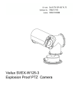
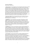
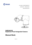
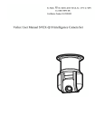
SVEX-HIR7 Explosion Proof PTZ Camera User Manual www.veilux.net SVEX-HIR7 Explosion Proof PTZ Camera USER MANUAL Copyright ©2013 Veilux Inc. All rights reserved. Trademark is the registered logo of Veilux Inc. The name of this product is the registered trademark of Veilux Inc. Other trademarks mentioned in this manual are the registered trademark of their respective company. Disclaimer Veilux Inc makes the best to verify the integrity and correctness of the contents in this document, but no formal guarantee shall be provided. Use of this document and the subsequent results shall be entirely on the user’s own responsibility. Veilux Inc reserves the right to change the contents of this document without prior notice. -Design and specifications are subject to change without prior notice. Copyright Notice The content of manual book (including characters and pictures) owned Veilux. Neither person nor legal entity can‟t copy, translate, change or recompose without the permit by our company. The person who offends the copyright will be called to account by laws. Any specifications are subject to change without notice. The customers can get the latest information from http://veilux.net Safety Guarantee The running of equipment will be in accord with the following two demands „ The running of the equipment won‟t result in any disturbance. „ The running of the equipment won‟t be affected by exterior conditions, even from bad influence. Notice „ The customer can‟t take apart the equipment, such as disassemble the top cover or screws. It may leads to leak of water or electricity. Please operate the equipment under the demand of the manual book. „ Please use the equipment under the demand of air pressure, environment temperature, and humidity range in chapter 1.7. „ Make sure use the power in accord with the nameplate of the equipment. „ Inner and outer ground connection should be reliable. „ Make sure the installation position is steady to avoid camera damage. Thank you for choosing Veilux Ex-proof products. Please read the manual book before installation and application. Make sure to obey the warning and keep the manual book well. Safety Instruction The safety instruction of these series products „ „ „ Ensure supply power same as nameplate marked before equipment being powered Ensure supply a series long time, stable working power. A 3 meters control cable is equipped when leaving factory. The ex-proof flexibility tube will be used when the cable is connected with EX junction box. „ „ „ „ „ „ All ex-proof parts are stable and complete enough for structure Inside and outside ground connections are reliable. Please tear off the plug if the product is not used for a long time. Please communicate with technical person before maintaining the products. Please shut off before maintenance and repair Take care of products package for future shipment if necessary. Ex-proof Structure Instruction „ When we design the products, we have taken fully consideration of the situation that the explosive air getting into ex-proof structure. The inner electric parts‟ working won‟t lead to explosion in outside atmosphere. Key points such as housing intension, the joint surface length of components and the Max. Surface temperature is all considered to „ guarantee the explosion proof performance. Enclosure shall burden water pressure testing for 1.5Mpa for 10~12 seconds without leakage or shape change, which follows the requirement in GB3836.2-2000. „ „ „ „ Max. PTZ surface temperature shall not be over 80℃ while it is working. Tempered glass is used for window to burden impact and heat change testing. The protection of housing is IP68. Tightened nut is used for cable input to make cable tight and stable. Content 1. BRIEF................................................................................................................................ 9 1.1 SPECIFICATION................................................................................................................. 9 1.2 FEATURE........................................................................................................................... 9 1.3 SCOPE OF APPLICATION ................................................................................................ 9 1.4 TECHNICAL SPECIFICATION............................................................................................. 10 1.5 MECHANICAL ............................................................................................................. 10 1.6 WORKING CONDITION ..................................................................................................10 1.7 ENVIRONMENTAL ....................................................................................................... 11 1.8 ELECTRIC SAFETY (UNDER STANDARD AIR PRESSURE).................................................. 11 2. INSTALLATION AND DEBUGGING ........................................................................ 11 2.1 NOTICE BEFORE INSTALLING SVEX-HIR7 ................................................................. 11 2.2 SVEX-HIR7 INSTALLATION ........................................................................................ 13 2.2.1 Cable treatment................................................................................................... 13 2.2.1.1 Use ex-proof flexibility tube..................................................................................... 13 2.2.1.2 Use armored cable .................................................................................................. . 14 2.3 APPLICATION .............................................................................................................. 14 2.3.1 System connection .............................................................................................. 14 2.3.2 Cable definition.................................................................................................. 15 2.3.3 Parameter set .................................................................................................... 15 2.3.3.1 Camera address set ................................................................................................... 15 2.3.3.2 Baud rate set ............................................................................................................ 16 2.3.3.3 Communication protocol set..................................................................................... 16 2.3.3.4 Remote communication set ...................................................................................... 16 2.3.4 Menu function .................................................................................................... 17 2.3.5 Control Signal Connection................................................................................. 17 2.3.6 Preparation and examination before power on ................................................. 18 2.4 SUPPORTING BRACKET PREPARATION BEFORE INSTALLATION .................................... 19 2.4.1 Wall mounting installation (P 2.4.1.1)............................................................... 19 2.5 ON SITE INSTALLATION ............................................................................................... 20 2.5.1 Bracket mode installation (P2.5.1.1) ................................................................. 20 3. TROUBLE SHOOTING................................................................................................. 21 4. SHIPMENT AND STORAGE....................................................................................... 21 4.1 SHIPMENT NOTICE ...................................................................................................... 21 4.2 STORAGE DEMAND, PERIOD AND NOTICE .................................................................... 21 5. ATTACHED LIST ......................................................................................................... 22 5.1 CAMERA/OPTIC DATA................................................................................................... 22 8 1. BRIEF As new monitoring equipment, SVEX-HIR7 explosion proof PTZ camera adopts advanced production techniques and matured quality management system to make its quality, performance and appearance a leading position in explosion proof monitoring products. It can be used in flammable and explosive environment to realize monitoring purpose. Strictly according to Standards of GB3836.1-2000 GB3836.1—2000 Electrical apparatus for explosive atmosphere: General requirements, GB3836.2-2000 Electrical apparatus for explosive atmosphere: Flameproof „d‟ and GB12476.1-2000 Electrical apparatus for explosive dust: Using enclosure and limiting surface temperature for protecting electrical apparatus Chapter 1: Technical requirements, this camera owns advantage of small volume, light weight and easy installation features and could be used in petroleum, chemical industry, jetty, port, mine, space, army and foodstuff area. 1.1 Specification Model SVEX-HIR7 IP level IP68 Ex-marking ExdⅡCT6 / DIP A20 TA, T6 Camera model Sony 1.2 Feature SVEX-HIR7 adopts advanced color camera, speed pan/tilt and decoder. It is integrated with multiple communication protocol and baud rate. It will play an important role in several types of safety system. SVEX-HIR7 has wide voltage scope; it can automatically detect several kinds of camera. It has power, signal, and video trebling lightning protection, safer and reliable. SVEX-HIR7 adopts integrated structure design. There is no cable connected between pan/ tilt and camera. The pan rotation is 360° continuous, tilt rotation is .±90°. They are equipped with sunshield, wiper and auto heat equipment. 1.3 Scope of application It could be widely used in zoneⅠ, Ⅱ for gas area and A20~A22 dust area. 9 1.4 Technical specification Pan speed Tilt speed 0.1°~40°/S smooth variable speed 0.1°~40°/S smooth variable speed Preset speed 60°/S Preset quantity 128 Preset position error ≤0.1 ° Surge protection Auto- heater signal/video/power surge protection module integrated work while under -10℃ 1.5 Mechanical Material Stainless steel 304 Pan rotation Tilt rotation 360° continuous +90°~ -90° Unit weight 29Kg(net weight) Shipment weight 32Kg(gross weight) Mounting Base, ceiling mounting Face view P 1.5.1.1 Side view Product Dimension 1.6 Working condition Input voltage 100 ~ 240 VAC Max current ≤1A Power ≤100W Electrical connection 3 meters composite cable Communication type Baud rate RS-485 1200、2400、4800、9600bps, 4800bps as default 10 Communication protocol Address code PELCO-P、PELCO-D, PELCO-D as default 1~255,1 as default 1.7 Environmental Air pressure Environment temperature Relative Humidity Environment Min. illumination 86 ~ 106 KPa -40℃ ~ +60℃ U95 %RH (+25℃) Sony FCB-EX480CP 0.7Lux(C)/ 0.01Lux(B/W) 1.8 Electric safety (under standard air pressure) Insulating resistance: Over 100 MΩ resistance between power input terminal and housing; Power frequency withstand voltage: power input terminal and housing can bear 50Hz, 2000V voltage power frequency voltage for one minute without breakdown or flashover. 2. INSTALLATION AND DEBUGGING 2.1 Notice before installing SVEX-HIR7 Check all parts in packing before installation SVEX-HIR7 PTZ,1 unit Sunshield ,2 units 11 Hexagonal bolt Brass screw Brass screw Flat gasket Spring washer M16×30,3 pcs 1/4″×6, 1 pc 1/4″×12, 1 pc Ø16, 3 pcs Ø16, 3 pcs Special wrench, 1 pc Desiccant, 1 pc Teco521 special grease, 1 unit The tools and other parts which will be used Cross screwdriver 6×150, 1 unit External hexogen wrench 300×36, 1unit 12 Notice before installation and application „ „ „ „ Customer can’t disassemble product without permit. Follow the demand of manual book. Power supply must be in accord with chapter 1.4. Make sure to operate the equipment under the specified conditions in chapter 1.5. Debug the products first if possible before on-site installation. 2.2 Installation 2.2.1 Cable treatment 2.2.1.1 Use ex-proof flexibility tube ■ As P2.2.1.1, put on the Ex-proof flexibility part to cable, remove the tighten nut, keep the original gasket and rubber loop (or use the spare parts). Ex-proof Flexible Tube Gasket Screw Joint Cable Outlet Rubber Loop Cable P 2.2.1.1 ■ As P2.2.1.2, firstly turn tight the screw connection head and then tight the EX-proof flexibility tube. Ex-proof Flexible Tube Cable Outlet P 2.2.1.2 13 2.2.1.2 Use armored cable ■ As P 2.2.1.3, remove proper length cable protection cover and cut off not used part. Ex-proof Gland Parts Armored cable Protection Cover Cable inner layer Steel belt Cable core wire Rubber Sealing Loop Nut Bushing Bushing Connection Taper Volt Gasket P 2.2.1.3 ■ As P2.2.1.4, install Ex-proof Gland to Armored Cable Armored cable Out Cover Finished Gland Cable Inner Layer Screw Thread P 2.2.1.4 ■ Armored cable with ex-proof Gland could connect with any ex-proof equipment directly. 2.3 Application 2.3.1 System connection P 2.3.1.1 System Connection Video Signal could connect with multiple equipment‟s, such as monitor for display, DVR for Installation & product debugging | 13 14 Ver: 0.1 record or video server for network transmission or matrix for switch and management. Video distributor can distribute and amplify the video signal. All control equipment could control this Camera under the same control protocol. Some Matrix may need protocol converter; some DVR may need RS232-RS485 level converter. Normally one RS485 Bus only permits one host controller. So if several host controllers want to control simultaneously, users‟ authority can be used. 2.3.2 Cable definition While camera leaves factory, we supply a Composite Cable* with camera, the cable goes out from Camera bottom with length at least 2 meters. So while connecting the system, just connect the cable with junction box. (*Composite Cable: A special cable, one Composite Cable includes one group power, one group control and one group video, it is generally used in Industrial CCTV system.) T 2.3.2.1 Cable Definition Composite Cable Name Power cable Control (shielded) Function L wire N wire Earth wire RS485-A RS485-B Color Brown Grey Yellow/Green Red Blue Video cable SYV-75-2 coaxial cable 2.3.3 Parameter set Parameter setting method: open top cover with special wrench and set the address, baud rate, communication protocol by dip switch K1、K2、K3、K4、K5. Re power on if the setup is changed. The version number, control protocol, baud rate and address of camera will be displayed each time when energized as following: Version Protocol Baud rate Address VERSION:1.0 PROTOCOL:PELCO-P BAUD:4800 CAMERA ID:001 2.3.3.1 Camera address set Camera address adopts decimal system. Normally address has been set down before camera leaving factory, K1、K2、K3 should be set by address. K1 stands for unit digit, K2 for tens place, K3 for hundreds place. 15 For example: if the camera address is 1, K1 is 1, K2 is 0 and K3 is 0. Hundred place Dip switch Address No Tens place Unit place K3 K2 K1 0 0 1 For example: if the camera address is 118, K1 is 8, K2 is 1 and K3 is 1. Hundred place Dip switch Address No Tens place Unit place K3 K2 K1 1 1 8 2.3.3.2 Baud rate set Please set correct baud rate as follow: T 2.3.3.1 Baud rate set K4 value Baud rate 0 Remote communication setting 1 1200 2 2400 3 4800 4 9600 2.3.3.3 Communication protocol set Ensure the communication protocol of the controller. Set K5 as following table. T 2.3.3.2 Communication protocol set K5 value Protocol 1 PELCO-P 2 PELCO-D 2.3.3.4 Remote communication set When K4 sets 0, we can remotely set equipment address, control protocol and baud rate. (Right now the default baud rate is used, which is displayed when system is power on). At this time, all setting with K1, K2, K3 and K5 cannot work. The On-screen-display menu can be reached by following procedure: run No.95 Preset, press “MAIN MENU” “CONTROL” “RS485”. 16 2.3.4 Menu function The camera has the menu function. Enter the menu model: invoke main menu by running No. 95 preset when the system is ready. After menu displays, pan/tilt up, down, left, right, aperture OPEN, CLOSE become menu control key. At this time, the other key can‟t work. All “<>”mark means there is submenu. The present page menu is selected by up, down key. The parameter is controlled by left and right key. “OPEN” means “OK”. Press “OPEN” key to enter next menu. If the menu item is selected, the menu will glitter. If the system is scanning model, left down corner will display “RETURN:CLOSE”. Please press “aperture close” to exit, then the camera can be controlled. 2.3.5 Control Signal Connection While this system works at industrial site, it must go with explosion proof Junction box, in which we can make the connection of cables of video, control and power. While the control signal and camera goes as STAR type connection, we shall use control ■ code distributor, at this time each communication board of camera shall use a 120Ohm resistor to connect Side A and B (Change DIP on the RS485 communication board ON), Camera Camera AB Gnd AB Gnd 120Ω AB Gnd AB Gnd AB Gnd AB Gnd Control code AB Gnd 120Ω Camera Camera 120Ω AB Gnd 120Ω AB Gnd Control signal source AB Gnd P 2.3.5.1. Camera STAR Connection ■ While Control Signal Source connection with Camera as Chrysanthemum type, just to ada120Ohm resistor to the end of camera Side A and B.(to get rid of others JMP1 on communication board) 17 Camera A B Gnd A B Gnd Camera A B Gnd Camera A B Gnd 120Ω Control P 2.3.5.2. Camera Connection of Chrysanthemum 2.3.6 Preparation and examination before power on Check if power, RS485 control and video cable are connected correctly. Check the dip switch settings. 18 2.4 Supporting bracket preparation before installation 2.4.1 Wall mounting installation (P 2.4.1.1) Bracket Make a mount hole at proper level and fix the bracket with screw. Junction Box shall be installed Wall for easy operation and maintenance. Cable gets through the cable slot and connects the junction box. See P2.4.1.2 for the mounting base specification. SVEX junction box P P 2.4.1.2 2.4.1.1 Bracket Cable slot and junction installation Bracket foundation mounting specification size 19 2.5 On site installation Because of the particularity of the ex-proof product, test and debug the camera first if possible before on site installation. SVEX-HIR7 PTZ Camera 2.5.1 Bracket mode installation (P2.5.1.1) Refer to P2.4.1.2 for camera mounting holes, and make the camera cable go through cable hole on the bracket until reaching Junction Box. Use ex-proof flexibility tube for protection or armored cable. The cable which connects junction box with control room must be metal tube or armored cable P 2.5.1.1 SVEX-HIR7 bracket installation 20 3. TROUBLE SHOOTING Problems Reason Method Power off Make sure the power is ok No action or no image Power line without good after power on connection Inner power damage Coaxial-cable wrong Self-check is ok, but no image connection Coaxial-cable in bad connection Camera damage Sometimes no image Self-check is ok, but control error Video cable in bad connection Bad connection of Signal cable Check the power line Contact the factory and replace Check coaxial cable Check coaxial cable Contact the factory and replace Check the Video Cable Check Signal Cable connection Not correct Address Not correct Protocol Re-set refer to Manual book Not correct Baud rate Self-check error Control signal line in bad Control error connection Loading too much Too long communication distance Power on again Check control line connection Add control code distributor Add repeaters to make communication distance longer 4. SHIPMENT AND STORAGE 4.1 Shipment notice Without rain or snow falling directly to product, packed product can be shipped by any way. 4.2 Storage demand, period and notice It can be stored for one year under 0℃~+40℃ and less than 90% humidity. 21 5. ATTACHED LIST 5.1 Camera/Optic data The two following integrated cameras are typical. The other types can be used after Veilux confirmation. ------------------------------------------------------------------------------------------------------Brand SONY Mode PAL / NTSC CCD 1/4″ Exview HAD CCD Line/Frame scan 15.625 KHz/ 50Hz Lens High performance /18X optic zoom / auto focus / F1.4~3.0, f=4.1~ Min focus View angle Min Lux 73.8mm /12 digital zoom 0.29m (wide)/ 0.8m(tel) 48°(wide)/ 2.8°(tel) 0.7Lux(color)/ 0.01Lux(b/w) SNR > 50dB Video output BNC / 1.0Vp-p / 75Ω 6. GUARANTEE For any camera produced by VEILUX, INC, we promise one year warranty. During warranty, we supply free service except following situations: User does not operate as manual book requires Product maintenance, storage and shipping | 21 22 User un-install the whole product by themselves Lightning or Act of God If there are additional agreements between VEILUX, INC and buyer, then agreements shall be strictly done. 7. STATEMENT VEILUX, INC. owns the final design changing and final specification rights and no responsibility to inform user This manual book belongs to VEILUX, INC. rights, without permits or any book inform, any company or private copy of whole or part of the book shall be prohibited. 802 Greenview Dr. Suite 200 Grand Prairie, TX 75050 USA Toll free: 1-800-510-6528 Direct: (+1) 214 635-4855 [email protected] www.veilux.net 23