1
<<Contents>> <<Index>>
General
Specifications
YTMX580
Multi-Input Temperature Transmitter
GS 04R01B01-01EN
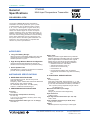
The model YTMX580 Multi-Input Temperature
Transmitter can accept inputs from up to 8 points
of measurement such as thermocouples (8 types:
K, E, J, etc.) or RTD signals (3 types: Pt100, etc.),
converting the corresponding measurement input
values to a wireless signal. It can also accept DC
voltage, resistance, and 4–20 mADC signal input. In
addition to temperature signals, it can also wirelessly
send and receive setting parameters. Internal battery
power means eliminating not only signal wires, but
also power cables—this offers great installation cost
reductions. The communication is compliant with
ISA100.11a protocol specifications.
FEATURES
● Long Life Battery Design
Ultra low current consumption design using two high
capacity lithium-thionyl chloride batteries provide
wireless operation for years.
● High Security Wireless Network Configuration
Infrared communication between the devices for
wireless network configuration and parameter setting.
● Quick Update Time
Selectable from 1 second to 60 minutes for measured
process value to publish wirelessly.
STANDARD SPECIFICATIONS
■ WIRELESS SPECIFICATIONS
Communication protocol: ISA100.11a protocol
Data rate: 250 kbps
Frequency: 2400 - 2483.5 MHz license free ISM band
Radio security: AES 128 bit codified
RF Transmitter power: Max. 11.6 dBm (fixed)
Antenna: +2 dBi Omni directional type
■ PERFORMANCE SPECIFICATIONS
Accuracy
See Table 1.
Cold Junction Compensation Accuracy
For T/C only
± 0.5 °C (± 0.9 °F) (added to accuracy when using
thermocouple input)
Ambient Temperature Effect (per 1.0 °C change)
See Table 2.
Battery Pack
Battery pack with long life lithium-thionyl chloride
batteries. With the intrinsically safe type, the battery
pack is replaceable in a hazardous area. Typical
battery life is 6 years at 60 seconds publication
period (update time) in the following conditions.*
• Network connection: JOIN status
• Ambient temperature: 23±2 °C
• Device role: IO function only
• LED indicator: off
* Environmental condition such as ambient
temperature and vibration may affect the battery
life.
■ FUNCTIONAL SPECIFICATIONS
Input
channels:8 points
Input type is selectable: Thermocouples, 2-, 3-, and
4-wire RTDs, ohms, DC milivolts and DC miliamperes
(4 to 20 mA, with external shunt resistors). See Table 1.
Note: Explosion proofing not applicable during DC volts and
DC miliamperes input.
Maximum Allowable Input voltage
±2.5 VDC
Category O (Transient overvoltage 330V)
Input Resistance
10 MΩ or more
Input Signal Source Resistance (for T/C, mV)
1 kΩ or lower
Input Lead Wire Resistance (for RTD, Ohm)
10 Ω per wire or lower
Output
Wireless (ISA100.11a protocol) 2.4 GHz signal.
Yokogawa Electric Corporation
2-9-32, Nakacho, Musashino-shi, Tokyo, 180-8750 Japan
GS 04R01B01-01EN
©Copyright September 2011
7th Edition Feb. 27, 2014
2
<<Contents>> <<Index>>
Measurement Range
See Table 1.
Publication Period (Update Time)
1 to 3600 sec selectable.
Minimum of 2 seconds with 4 or more measuring
points.
Zero-gain Adjustment
Set the amount of zero-gain point adjustment.
Status Display
The RDY (green) and ALM (red) LEDs indicate the
following statuses: Starting, Running, Waiting to
"JOIN" (network), Squawk, Alarm, Deep Sleep
Sensor Burnout
Select HIGH, LOW or OFF as the configuration. (use
setting software)
Self Diagnostics
Amplifier failure, sensor failure, configuration error,
battery alarm, wireless communication alarm and
over-range error for process variables.
Software Download Function
Software download function permits to update
wireless field device software via ISA100.11a
wireless communication.
Device Role
The following 2 device roles are supported depending
on the network topology.
• IO Function only (IO)
• IO Function and Routing Function (IO + Router)
Device Role
IO
IO+Router
Network form
Star
Mesh
GW
GW
Example network
connections and
devices
IO
IO
IO
GW : Gateway
IO : YTMX580
IO+R
IO+R
IO
IO
IO
GW : Gateway
IO + R : YTMX580
IO : YTMX580
E01.ai
Infrared Communication
Data rate:9600 bps
Distance:Infrared surface of the near infrared adapter
should be within 30 cm
Power Supply
2x primary lithium-thionyl chloride batteries (size D)
With battery case (batteries sold separately)
Insulation Resistance
Measuring input terminal to ground terminal:
100 MΩ or greater (at 500 VDC)
Dielectric Strength
Dielectric strength that can withstand the following
conditions
Measuring input terminal to ground terminal:
500 VAC (50/60 Hz), 1 min, leakage current of
5 mA or less
Between measuring input terminal:
200 VAC (50/60 Hz), 1 min, leakage current of
5 mA or less
All Rights Reserved. Copyright © 2011-2014, Yokogawa Electric Corporation
■ NORMAL OPERATING CONDITION
(Optional features or approval codes may affect
limits.)
Ambient Temperature Limits
-40 to 85 °C (-40 to 185 °F)
As for explosion protect type, see
REGULATORY COMPLIANCE STATEMENTS
Ambient Humidity Limits
0 to 100 % RH
Storage Temperature
-40 to 85 °C (-40 to 185 °F)
Vibration
3G or less, at resonant frequencies from 10 to 2000
Hz (IEC 60770-1)
■ REGULATORY COMPLIANCE STATEMENTS
This device contains the wireless module. The
wireless module satisfies the following standards.
* Please confirm that a installation region fulfills
a standards, require additional regulatory
information and approvals, contact to Yokogawa
Electric Corporation.
Safety Standards
EN61010-1, EN61010-2-030,
CSA C22.2 No.61010-1-12
CSA C22.2 No.61010-2-030-12
UL 61010-1, UL 61010-2-030 (CSA NRTL/C)
Overvoltage Category I, Pollution Degree 2
Indoor/Outdoor use
EMC Conformity Standards
EN61326-1 Class A Table 2 (For use in industrial
locations), EN61326-2-3, EN 301 489-1, EN 301
489-17
R&TTE Conformity Standards
ETSI EN 300 328, ETSI EN 301 489-1,
ETSI EN 301 489-17, EN60950-1, EN62311
Regulation Conformity of the Wireless Module
• FCC Approval
• IC Approval
• Japanese Radio Law ( Construction Design
Attestation Number: 007WWCUL0480)
Korea Certification ( Radio Wave Act )
KCC-REM-YHQ-WEN007
EMC and Radiocommunications regulatory
arrangement in Australia and New Zealand (RCM)
AS/NZS 4268
AS/NZS 2772.2
EN61326-1 Class A, Table2 (For use in industrial
location)
GS 04R01B01-01EN
Feb. 27, 2014-00
3
<<Contents>> <<Index>>
Explosion Protection
FM Intrinsically safe, nonincendive Approval
Intrinsically Safe for Class I, Division 1,
Groups A, B, C & D, Class II, Division 1,
Groups E, F & G and Class III, Division 1,
Class I, Zone 0, in Hazardous Locations, AEx ia IIC
Nonincendive for Class I, Division 2,
Groups A, B, C & D, Class II, Division 2,
Groups F & G and Class III, Division 1,
Class I, Zone 2,
Group IIC, in Hazardous Locations
Sensor Circuit Parameter: Voc, Uo= 5.88 V,
Isc, Io= 130.1 mA, Po= 191.2 mW, Ca, Co= 1 μF,
La, Lo= 1 mH
Ambient temperature: –50 to 70 °C ( - 58 to 158°F )
CSA Intrinsically safe Approval, non-incendive
Approval
Intrinsically Safe for Class I, Division 1, Groups A,
B, C & D, Class II, Division 1, Groups E, F & G,
Class III, Division 1
Non-incendive for Class I, Division 2,
Groups A, B, C & D, Class II, Division 2,
Groups F & G, Class III, Division 1
Enclosure: Type 4X, IP66/IP67
Temperature Code: T4
Ambient temperature: –50 to 70 °C
Ex ia IIC T4
Sensor Circuit Parameter: Uo= 5.88 V,
Io= 130.1 mA, Po= 191.2 mW, Co= 1 μF,
Lo= 1 mH
ATEX Intrinsically safe Approval
II 1 G Ex ia IIC T4 Ga
Sensor Circuit Parameter: Uo= 5.88 V,
Io= 130.1 mA, Po=191.2 mW, Co= 1μF,
Lo= 1 mH
Ambient temperature: –50 to 70 °C
IECEx Intrinsically safe Approval
Ex ia IIC T4 Ga
Sensor Circuit Parameter: Uo= 5.88 V,
Io= 130.1 mA, Po= 191.2 mW, Co= 1 μF,
Lo= 1 mH
Ambient temperature: –50 to 70 °C
TIIS intrinsically safe Approval
Ex ia IIC T4 X
Power Supply: Battery pack (F9915MA) or battery
case (F9915NS) DC7.2V
Sensor Input Circuit: Uo= 5.88 V, Io= 130.1 mA,
Po= 191.3 mW, Co= 1 μ F, Lo= 1 mH
Ambient temperature: –20 to 60 °C
*
The remote antenna model (antenna suffix code
B) is not applicable.
All Rights Reserved. Copyright © 2011-2014, Yokogawa Electric Corporation
■ PHYSICAL SPECIFICATIONS
Enclosure
Housing
Low copper cast aluminum alloy
Coating
• Standard coating
polyurethane, mint-green paint. (Munsell 5.6 BG
3.3/2.9 or its equivalent)
• High anti-corrosion coating (Option Code /X2)
Base coating: epoxy resin coating
Finish coating: polyurethane coating
The color is same as standard type.
Degrees of Protection
IP66/IP67, NEMA Type 4X
Connection Terminal
4 mm Screw terminal
Name Plate and Tag
316 SST
Mounting Blacket
316 SST
Select pipe mounting or wall mounting
Weight
3.2 kg (7.05 lb)
Without mounting bracket.
Connections
Refer to “MODEL AND SUFFIX CODES.”
■ ACCESSORIES
Remote Antenna Cable (optional accessories)
(Only by order of option)
Specification of Cable: 8D-SFA(HDPE)
Outside Diameter of Cable: 11.1 mm
Minimum Bend Radius: 67 mm (when fixing)
167 mm (when wiring)
Cable End Treatment: N type connector, one end is
male and the other is female.
Operational temperature range: -40 to +85 °C
( - 40 to 185°F )
*“When fixing” shows the bending radius for fixing (the
state is maintained for a long time).
“When wiring” shows the bending radius while
checking the wiring position. This bending radius
is set larger than that for fixing in order to prevent
damage to the cable because the cable is likely to
be repeatedly bent when checking the final wiring
position.
GS 04R01B01-01EN
Feb. 27, 2014-00
4
<<Contents>> <<Index>>
Table 1. Sensor type, measurement range, and accuracy
Sensor Type
Standard
Measurement Range
100 to 1820 °C ( 212.0 to 3308.0 °F )
B
E
-200 to 1000 °C ( -328.0 to 1832.0 °F )
J
-180 to 760 °C ( -292.0 to 1400.0 °F )
K
T/C
IEC584
N
-180 to 1372 °C ( -292.0 to 2501.6 °F )
-200 to 1300 °C ( -328.0 to 2372.0 °F )
0 to 1768 °C ( 32.0 to 3214.4 °F )
R
0 to 1768 °C ( 32.0 to 3214.4 °F )
S
T
-200 to 400 °C ( -328.0 to 752.0 °F )
-200 to 850 °C ( -328.0 to 1562.0 °F )
Pt100
-200 to 850 °C ( -328.0 to 1562.0 °F )
RTD
Pt200
IEC751
-200 to 850 °C ( -328.0 to 1562.0 °F )
Pt500
mV
V
Ohm
Note1:
Note2:
Note3:
Note4:
-
-10 to 100 [mV]
-0.01 to 1 [V]
0 to 2000 [Ω]
Accuracy
Accuracy not guaranteed for less than
400 °C ( 752.0 °F )
± 2.54 °C ( ± 4.57 °F ) in the range from
400 °C ( 752.0 °F ) or more to less than
800 °C ( 1472.0 °F )
± 1.54 °C ( ± 2.78 °F ) for 800 °C (
1472.0 °F ) or more
± 0.80 °C ( ± 1.44 °F ) for less than 0 °C
( 32.0 °F )
± 0.40 °C ( ± 0.72 °F ) for 0 °C ( 32.0 °F
) or more
± 0.80 °C ( ± 1.44 °F ) for less than 0 °C
( 32.0 °F )
± 0.70 °C ( ± 1.26 °F ) for 0 °C ( 32.0 °F
) or more
± 1.10 °C ( ± 1.98 °F ) for less than 0 °C
( 32.0 °F )
± 1.0°C ( ± 1.80 °F ) for 0 °C ( 32.0 °F )
or more
± 2.0 °C ( ± 3.60 °F ) for less than 0 °C
( 32.0 °F )
± 1.0 °C ( ± 1.80 °F ) for 0 °C ( 32.0 °F
) or more
± 2.00 °C ( ± 3.60 °F ) for less than 200
°C ( 392.0 °F )
± 1.50 °C ( ± 2.70 °F ) for 200 °C ( 392.0
°F ) or more
± 2.00 °C ( ± 3.60 °F ) for less than 200
°C ( 392.0 °F )
± 1.40 °C ( ± 2.52 °F ) for 200 °C ( 392.0
°F ) or more
± 0.70 °C ( ± 1.26 °F )
± 0.30 °C ( ± 0.54 °F ) for less than 400
°C ( 752.0 °F )
± 0.40 °C ( ± 0.72 °F ) in the range from
400 °C ( 752.0 °F ) or more to less than
500 °C ( 932.0 °F )
± 0.50 °C ( ± 0.90 °F ) for 500 °C ( 932.0
°F ) or more
± 0.54 °C ( ± 0.98 °F ) for less than 400
°C ( 752.0 °F )
± 0.64 °C ( ± 1.15 °F ) in the range from
400 °C ( 752.0 °F ) or more to less than
500 °C ( 932.0 °F )
± 0.74 °C ( ± 1.33 °F ) for 500 °C ( 932.0
°F ) or more
± 0.38 °C ( ± 0.68 °F ) for less than 400
°C ( 752.0 °F )
± 0.48 °C ( ± 0.86 °F ) in the range from
400 °C ( 752.0 °F ) or more to less than
500 °C ( 932.0 °F )
± 0.58 °C ( ± 1.04 °F ) for 500 °C ( 932.0
°F ) or more
± 0.035 [mV]
± 0.001 [V]
± 1.0 [Ω]
For T/C input, add Cold Junction Compensation Accuracy (± 0.5 °C) to the total accuracy.
For RTD input of the 2-wire connection, add a corrected value (± 0.1 °C) to the total accuracy.
For DC miliamperes (4 to 20 mA), connect external shunt resistors.
Explosion proofing not applicable to [DC volts, DC miliamperes].
All Rights Reserved. Copyright © 2011-2014, Yokogawa Electric Corporation
GS 04R01B01-01EN
Feb. 27, 2014-00
5
<<Contents>> <<Index>>
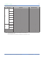
Table 2. Effects of ambient temperature
Temperature Effects per 1.0°C Change in Ambient
Temperature
Sensor Type
B
E
J
T/C
K
N
R, S
T
Pt100
Pt200
RTD
Pt500
0.2 °C - ( 0.066 % of ( t - 100 ) )
t < 300 °C
0.07 °C - ( 0.0057 % of ( t - 300 ) )
300 °C ≤ t < 1000 °C
0.037 °C
t ≥ 1000 °C
0.035 °C - ( 0.00492 % of t )
t < 0 °C
0.035 °C - ( 0.00146 % of t )
t ≥ 0 °C
0.0039 °C - ( 0.00529 % of t )
t < 0 °C
0.0039 °C + ( 0.00149 % of t )
t ≥ 0 °C
0.00521 °C - ( 0.00707 % of t )
t < 0 °C
0.00521 °C + ( 0.00182 % of t )
t ≥ 0 °C
0.0077 °C - ( 0.00918 % of t )
t < 0 °C
0.0077 °C + ( 0.00136 % of t )
t ≥ 0 °C
0.04 °C 0 + ( 0.0102 % of t )
t < 100 °C
0.0316 °C - ( 0.001 % of t )
100 °C ≤ t < 600 °C
0.0175 °C + ( 0.00173 % of t )
t ≥ 600 °C
0.00513 °C - ( 0.00631 % of t )
t < 0 °C
0.00513 °C + ( 0.0008 % of t )
t ≥ 0 °C
0.0048 °C + ( 0.0016 % of absolute value t )
Entire Sensor Input Range
0.0038 °C + ( 0.0015 % of absolute value t )
t < 650 °C
0.0028 °C + ( 0.0016 % of t )
t ≥ 650 °C
0.003 °C + ( 0.0014 % of absolute value t )
t < 650 °C
0.002 °C + ( 0.0016 % of t )
t ≥ 650 °C
mV
0.0002 mV + ( 0.0015 % of reading )
Entire Sensor Input Range
V
0.005 mV + ( 0.0015 % of reading )
Entire Sensor Input Range
0.001 Ω + ( 0.0009 % of reading )
Entire Sensor Input Range
Ohm
Note1:
Note2:
Measurement Range
The “ t ” on Table 2 means the value of the reading in °C.
The “ absolute value t ” on Table 2 means the absolute value of the reading in °C.
[ Example of absolute value t ]
When the temperature value is 250 Kelvin, abs reading is 23.15, absolute (250 - 273.15).
All Rights Reserved. Copyright © 2011-2014, Yokogawa Electric Corporation
GS 04R01B01-01EN
Feb. 27, 2014-00
6
<<Contents>> <<Index>>
MODEL AND SUFFIX CODES
Model
YTMX580
Output Signal
Housing
Suffix Code
Descriptions
Multi-Input Temperature Transmitter
Wireless communication (ISA100.11a)
Always 7
G 1/2 female, nine electrical connections
1/2 NPT female, nine electrical connections
M20 female, nine electrical connections
None
316 SST 2-inch pipe mounting
316 SST wall mounting*1
-L
7
0
Electrical Connection 2
4
Integral Indicator
N
Mounting Bracket
L
W
N
Power Supply
Antenna*5
-A
A
B
Temperature Unit
-A
-B
--Option Codes
A
None
Battery (case only, battery not included), with a blind plug
Integral antenna
Remote antenna*4*6
Cel, K *2
Cel, K, degF, degR *3
Always A
Optional specifications (See Option Code)
*1: For wall mounting, please prepare bolts and nuts.
*2: This is a Japan-only specification (only available to end users inside Japan).
*3: In Japan, degF (°F) and degR (°R) are non-statutory measurement units. Suffix code -B can only be specified by end users
outside of Japan.
*4: Order the remote antenna cables separately from accessary option.
*5: Use of antenna is limited by local regulation of radio and telecommunication law. Consult Yokogawa for details.
*6: Not selectable for TIIS explosion proof specifications (suffix code: /JS37)
Note: " Cel " means " °C ", " degF " means " °F " and " degR " means " °R ".
OPTIONAL SPECIFICATION
Item
Coating
Factory configured settings
Description
High anti-corrosion coating
Factory configured settings with multiple input types/ ranges
Option Code
/X2
/FC1
OPTIONAL SPECIFICATION (For Explosion Protected type)
Item
Canadian Standards Association (CSA)
Factory Mutual (FM)
TIIS
ATEX
IECEx Scheme
Description
CSA Intrinsically safe and non-incendive approval
FM intrinsically safe and nonincendive approval
TIIS intrinsically safe approval
ATEX intrinsically safe approval
IECEx intrinsically safe approval
Option Code
/CS17*1
/FS17*1
/JS37*1*2
/KS27*1
/SS27*1
*1: /CS17, /FS17, /JS37, /KS27, /SS27 cannot be specified together.
*2: /JS37 can be specified on Integral antenna models (Suffix Code for Antenna is "A").
Standarad Accessories
Product
User's manual (Booklet)
Mounting bracket*1 (2-inch pipe mounting or wall mounting)
Battery case ( installed in the main body. )
Remote antenna*2
Qty
1
1 set
1
1
*1: Not included if specifying no mounting brackets ( mounting bracket suffix code is N ).
*2: With the remote antenna option ( Antenna Type suffix code B ).
All Rights Reserved. Copyright © 2011-2014, Yokogawa Electric Corporation
GS 04R01B01-01EN
Feb. 27, 2014-00
7
<<Contents>> <<Index>>
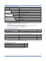
Optional Accessories
Product
Remote antenna cable*1
Model code (part number)
F9193UA
F9193UB
F9193UC
F9193UD
F9193UE
F9193DH
Antenna*1
Specification
Antenna cable: 1 m, Operational temperature range: -40 to +85
°C, With remote antenna mounting bracket.
Antenna cable: 3 m, Operational temperature range: -40 to +85
°C, With remote antenna mounting bracket.
Antenna cable: 4 m (1 m+3 m) with arrestor, Operational
temperature range: -40 to +85 °C, With remote antenna mounting
bracket.
Antenna cable: 6 m (3 m+3 m) with arrestor, Operational
temperature range: -40 to +85 °C, With remote antenna mounting
bracket.
Antenna cable: 13 m (3 m+10 m) with arrestor, Operational
temperature range: -40 to +85 °C, With remote antenna mounting
bracket.
+2dBi Remote Antenna (White)
*1: Use of remote antenna cable is limited by local regulation of radio and telecommunication law. Consult Yokogawa for
details.
Product
Battery pack assembly
Battery case
Batteries
Front door part
Bracket
Shunt resistor
Model code (part number)
F9915NQ*1
F9915NK*2
F9915NR
B8808DE
B8808DM
B8808DN
B8808EM
B8808DW
B8808DV
X010-050-1
Specification
Battery case, Lithium-thionyl chloride batteries 2 pieces
Battery case only
Lithium-thionyl chloride batteries, 2 pieces
Front door Gasket, 1 piece
Front door Bolt Cap (Long) , 1 piece
Front door Bolt Cap (Short) , 1 piece
Front door Bolt SUS316, 1 piece
2B Pipe Mounting Bracket SUS316
Wall Mounting Bracket SUS316
50 Ω± 0.1 %, for 4mm screw terminals, Operational temperature
range: -25 to +80 °C
*1: If you need F9915MA, please purchase F9915NQ. F9915NQ is a set of F9915MA and instruction manual.
*2: If you need F9915NS, please purchase F9915NK. F9915NK is a set of F9915NS and instruction manual.
Model
Surffix Code
YTMXBP
Type and Quantity
-A1
-A4
-A7
-C1
-C4
-C7
-D1
-D4
-D7
All Rights Reserved. Copyright © 2011-2014, Yokogawa Electric Corporation
Description
Blind plug for electrical connection
G 1/2, 1 piece
G 1/2, 4 pieces
G 1/2, 7 pieces
1/2 NPT, 1 piece
1/2 NPT, 4 pieces
1/2 NPT, 7 pieces
M20, 1 piece
M20, 4 pieces
M20, 7 pieces
GS 04R01B01-01EN
Feb. 27, 2014-00
8
<<Contents>> <<Index>>
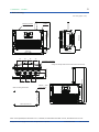
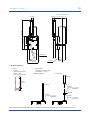
DIMENSIONS
● 2-inch pipe mounting (vertical or horizontal pipe)
Unit: mm (approx. inch)
147.3 (5.80)
67.3
(2.65)
45.2
(1.78)
110 (4.33)
89.5 (3.52)
173 (6.81)
164 (6.46)
Mounting bracket
118 (4.65)
118 (4.65)
133.8 (5.27)
120 (4.72)
48
48
48
48
125 (4.92)
2-inch pipe
(O.D. 60 mm)
Electrical connection
48
48
30
(1.18)
55.8
(2.20)
246 (9.69)
□ Height of directly attach the remote antenna to the body
(1.89)
48
89.5 (3.52)
(1.89)
E02.ai
Note: If not specified, the tolerance is 3 %. However, for dimentions less than 10 mm, the tolerance is 0.3 mm.
All Rights Reserved. Copyright © 2011-2014, Yokogawa Electric Corporation
GS 04R01B01-01EN
Feb. 27, 2014-00
9
<<Contents>> <<Index>>
● Wall mounting
Unit: mm (approx. inch)
48
184 (7.24)
164 (6.46)
10
256 (10)
143 (5.63)
10
(0.39)
276 (10.87)
48
256 (10.08)
4-Ø6.2
Mounting bracket
48
48
(1.89)
Electrical connection
48
48
4-Φ6.2±0.2 hole
or M5 tapping
164±0.5(6.46±0.02)
□ Wall mounting dimensions
338 (13.31)
48
(1.89)
335.5 (13.21)
51.3
30
(2.02) (1.18)
□ Height of directly attach the remote antenna to the body
256±0.5(10.08±0.02)
E03.ai
Note: If not specified, the tolerance is 3 %. However, for dimentions less than 10 mm, the tolerance is 0.3 mm.
All Rights Reserved. Copyright © 2011-2014, Yokogawa Electric Corporation
GS 04R01B01-01EN
Feb. 27, 2014-00
10
<<Contents>> <<Index>>
● Remote antena bracket
Unit: mm (approx. inch)
17 (0.67) 71.7 (2.82)
37.3 (1.47)
87.7 (3.45)
135 (5.31)
292 (11.50)
17.5 (0.69)
minimum R67
2-inch pipe
98 (3.86)
J04.ai
● Remote antenna
□ Antenna
□ Antenna cable
Antenna
* Non-direction antenna
* Gain : +2 dBi
*Part number: F9193DH
High-frequency coaxial cable
* Sheath dia : 11.11mm
<Without arrester>
<With arrester>
150
Antenna
Ø20.5
Antenna
18
Cable 2
Length : 3 m or 10 m
(selectable)
Arrester
Cable
Length : 1 m or 3 m
(selectable)
Main unit
Cable 1
Length : 1 m or 3 m
(selectable)
Main unit
E05.ai
Note: If not specified, the tolerance is 3 %. However, for dimentions less than 10 mm, the tolerance is 0.3 mm.
All Rights Reserved. Copyright © 2011-2014, Yokogawa Electric Corporation
GS 04R01B01-01EN
Feb. 27, 2014-00
11
<<Contents>> <<Index>>
● Infrared Configuration
● Terminal Configuration
Infrared port
E06.ai
Ground terminal
Ground terminal
E07.ai
● Input Wiring
(A)
(b)
(B)
(A)
(B)
(+)
(–)
TC or DC millivolts
two-wire
RTD or ohm
three-wire
RTD or ohm
(A)
(a)
(b)
(B)
four-wire
RTD or ohm
E08.ai
4~20mA
device
(–)
(–)
50Ω
(+)
(+)
Power
supply
DC milliamperes
( use a shunt resistor )
All Rights Reserved. Copyright © 2011-2014, Yokogawa Electric Corporation
GS 04R01B01-01EN
Feb. 27, 2014-00
12
<<Contents>> <<Index>>
< Ordering Information >
Specify the following when ordering Model, suffix
codes, and optional codes. The instrument is shipped
with the settings shown in Table A.
1. Sensor type.
1)Select an input sensor type from table 1. Each
input is of the same type.
2)For RTD and resistance input, specify the
number of wire as well. (Example; Pt100 3-wire
system)
3)With the /FC1 option (Factory configured settings
with multiple input types/ ranges), please indicate
the type of sensor for each input. You can also
select "NOT_USED" for inputs 2 through 8.
Note1: If the option code related to explosion protection
is specified, Either DCV (mV) or DCV (V) as
sensor type is should NOT be applied.
Note2: If the period of measurement is 1 second, the
maximum number of measuring points is 3. At
a 1-second period, the sensor type for at least 5
points must be set to “NOT_USED.”
2. Calibration range and unit (if required)
1)Calibration range can be specified within the
measurement range shown in Table 1.
With the /FC1 option, please indicate the upper
and lower limit values for each input. If /FC1 is
not specified, the upper and lower limit values for
all inputs will be the same.
2)Please specify the units of temperature for each
input (°C, °K, °F, or °R). °F and °R are available
when Temperature Unit suffix code -B is
specified. (In Japan, °F and °R are non-statutory
measurement units. Suffix code -B can only be
specified by end users outside of Japan.)
With the /FC1 option, please indicate the unit for
each input. If /FC1 is not specified, the unit for all
inputs will be the same.
It is not necessary to specify the unit of mV, V
and ohm inputs, for these units automatically will
be mV, V or Ohm.
3. Tag Number (if required)
Specify Tag number (up to 16 letters) to be
engraved on the tag plate. Also, the specified
letters are written to the “ Tag_Name “ (16 letters)
of the amplifier memory. The characters can be
specified using alphanumeric and the symbols,
[ - ] and [ . ]. Do not write anything to Tag number
when nothing is engraved on the tag plate.
4. Software tag (if required)
Specify this software tag when the tag number
required is different from the tag number
specified for the Tag plate. The tag number
specified in “Software tag” will be entered on
“Tag_Name” (up to 16 letters) in the amplifier
memory.
< Related Instruments >
Field Wireless Integrated Gateway YFGW710:
Refer to GS 01W01F01-01EN
Field Wireless Management Station YFGW410:
Refer to GS 01W02D01-01EN
Field Wireless Access Point YFGW510:
Refer to GS 01W02E01-01EN
Field Wireless Media Converter YFGW610:
Refer to GS 01W02D02-01EN
Versatile Device Management Wizard FieldMate:
Refer to GS 01R01A01-01E
Thermocouple :Refer to GS 06B01B01-00E,
GS 06B01E01-00E
Mineral Insulated Thermocouple :
Refer to GS 06B02D01-00E
Resistance Temperature Sensor :
Refer to GS 06B03B01-00E, GS 06B04D01-00E
Protection Tube, Thermowell :
Refer to GS 06B02T02-00E
Paperless Recorder DAQSTATION DX1000,DX2000:
Refer to GS 04L41B01-01E, GS 04L42B01-01E
Data Acquisition Unit MW100:
Refer to GS 04M10A01-01E
< Related Documents >
Field Wireless System Overview:
Refer to GS 01W01A01-01EN
< Trademarks >
All the brand names or product names of Yokogawa
Electric used in this document are either trademarks
or registered trademarks of Yokogawa Electric
Corporation.
Company and product names used in this manual are
trademarks or registered trademarks of their respective
holders.
The company and product names used in this manual
are not accompanied by the trademark or registered
trademark symbols (" ™ " and " ® ").
Note Lower-case alphabet characters and periods
[ . ] cannot be used in Yokogawa’s configuration
software. Specify the tag name (Tag_Name) using
a combination of upper-case alphabet characters,
numbers, and hyphens [ - ].
< Factory Setting >
Table A. Settings upon shipment
Tag No.
Calibration range and unit
“Blank” or as specified in order
See Table 1. Measurement Range
or as specified in order
All Rights Reserved. Copyright © 2011-2014, Yokogawa Electric Corporation
Subject to change without notice.
GS 04R01B01-01EN
Feb. 27, 2014-00