1
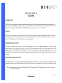
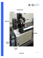
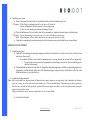
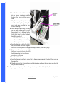
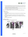
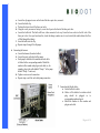
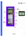
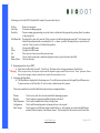
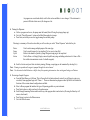
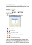
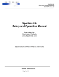
Quick-Start Guide XYZ3050 Benchtop Dispense Workstation Quick Start Guide To XYZ3050 INTRODUCTION The XYZ systems are designed to dispense reagents onto membranes for the development and manufacture of rapid diagnostic tests. Each system can be configured to dispense either via contact (Front Line), non-contact (BioJet or AirJet) dispensing, or a combination. There are three platforms: ZX1000, XYZ3050, and XYZ3200. This quick-start guide covers the XYZ3050. XYZ3050 The 3050 is an XY dispense system with motorized Z-axis and fully programmable co-ordinates and dispense parameters. It also has the capability for simultaneous dispensing or individual dispense of lines and dots. Using the 3050 platform, a maximum of 8 Front Line, or 8 BioJet Quanti, or 4 AirJet Quanti dispensers can be configured. REQUIREMENTS FOR SETUP You will need a surface that is level and flat and that will support the system’s weight and dimensions – the system weighs approximately 45 lbs and requires a surface space of 32in (system width, including clearance to allow for left/right movement of the dispense surface) by 22in (height) and 14in (depth). You will also need an allen wrench set (provided) and screw drivers (not provided). Finally, you will need a power supply (which must be grounded) and if you will be using an AirJet you will also need an air supply. INSTRUCTIONS FOR UNPACKING Your system will arrive in one large box, within which you will find two smaller boxes as well as the system’s platform. One box will contain the dispenser support arm and the other box will contain all accessories and components you will need to assemble the system. Note: On the next page you will find a labeled image of an XYZ system which you will find useful to review and refer back to as you go through this guide. www.biodot.com Page 1 of 14 www.biodot.com Page 2 of 14 1. Unpacking your system: a. Remove the items listed above (that is, the platform and the two boxes) from the large box. **Warning: When lifting the platform from the box, be sure to lift it from the bottom. Attempting to lift the instrument by the syringe pumps, X-Axis, etc., may misalign or permanently damage the unit. b. Place the platform on a flat, level surface that will accommodate its weight and size and remove the shrink wrap. **Warning: Do not plug anything in to a power source yet – this will be done as the last step. Note: Motorized parts will move freely when the system is not powered on; this is okay. c. Open the box containing the accessories and parts so that you can remove parts from the box as you need them. SETTING UP YOUR SYSTEM 2. Assembling the y-arm: a. Open the box containing the dispensing support arm. Remove it from the box. Locate the two screws within this box and remove them as well. i. If you find it difficult to access these two mounting screws, you may remove the top cover of the y support arm. 1. To remove the cover, unscrew the 8 supporting screws and then you can access the two mounting screws with the t-allen wrench. b. On the platform, locate the two holes that will support the dispensing support arm. Position the dispensing support arm appropriately (so that the holes in the base of the dispensing support arm are lined up with the holes in the top of the platform) and screw it on to the platform. 3. Assembling the dispense head: Note: How you assemble your dispense head will depend on how many dispensers you purchased, what combination of dispenser types you’re using, as well as what size head (or heads) you will be using. Additionally, if you are using an AirJet, please note that it has its own head and will typically be positioned first on the support arm (that is, in the first position when viewing the support arm from left to right). The instructions below are for a system configured with 1 AirJet and 1 BioJet. a. Locate the AirJet head. www.biodot.com Page 3 of 14 b. Locate the attachment screws that are screwed into the dispenser support arm; note the location of these screws and then remove them. c. Using the screws you have just removed, screw the head into position, positioning the screws in the same places that they were located a moment ago. d. Locate the output reagent tubing (the tubing that will connect from the right side of the three port valve to the dispenser) for the AirJet (AirJet tubing has a blue ferrule and brown fitting on each end). i. Note: Pull the blue ferrule away from the brown fitting to prevent twisting the line as you screw it in. e. Screw the tubing into the back of the AirJet; next, screw the other end of this tubing into the right side of the three port valve on the appropriate pump (in this case, the first/far left pump). Note: Steps c and e can be reversed; some users might find it easier to screw the tubing in to the AirJet head before mounting it, as it can be hard to access once it’s on the system. f. Locate the BioJet head. g. Locate the attachment screws that are screwed into the dispenser support arm; note the location of these screws and then remove them. h. Using the screws you have just removed, screw the head into position, positioning the screws in the same places that they were located a moment ago. Note: The user can choose to position the heads on the support arm in any way that works best for them; the screws are inserted as place holders as recommendation only. www.biodot.com Page 4 of 14 i. Locate the output tubing (the tubing that will connect from the right side of the three port valve to the dispenser) for the BioJet (BioJet tubing has a blue ferrule and brown fitting on one end (the end that attaches to the three port valve) and a green slide fitting on the other end (the end that attaches to the dispenser)). j. Position the green end of the tubing over the BioJet dispenser and slide down the green fitting; next, screw the other end of this tubing in to the appropriate pump (in this case the second pump). Note: If you have any additional BioJet dispensers, repeat steps i and j until each of your dispensers is attached to a pump. 4. Mounting the syringes: a. Locate your syringes. b. Screw the syringe in to the bottom hole in the three port valve, being careful not to strip it (it should screw in with no resistance). c. Grasp the syringe’s plunger and pull it down, extending it as far as it will go and inserting it into the hole below. d. Once the plunger is extended all the way down (this is important), screw it in by turning the silver wheel at the base of the pump. e. Repeat steps a through c for all pumps. 5. Mounting your vials/bottles: Note: Not all users will use bottles. If you are not using bottles, skip to step #6. www.biodot.com Page 5 of 14 a. b. c. d. e. Locate the clip support screw on the front of the three port valve; remove it. Locate the bottle clip. Position the clip in front of the three port valve. Using the screw you removed in step a, screw the clip on to the front of the three port valve. Locate the bottle/vial. The bottle will have a tube connected to its cap. Screw the loose end in to the left side of the three port valve. Once you have done this, check the tubing to make sure it is not twisted (this could obstruct the flow of fluid through the tubing) f. Insert the bottle into the clip. g. Repeat steps a through f for all pumps. 6. Connecting the harness: a. Locate the harness (the netted cables). b. Locate the ports on the back of the pumps. c. Each pump is labeled with a number and each cable is labeled with a corresponding number. Match like number to like number and plug in each cable (so, for example, plug in the cable labeled “Pump 1” to the pump labeled “Pump 1” and so on). d. Tighten screws on each connection. e. Repeat steps c and d for each cable/pump connection. 7. Connecting the BioJet cables: a. Locate the BioJet cables. b. Cables will be labeled to indicate which plug should be plugged in to corresponding numbered ports. c. Match like number to like number and plug in each cable. www.biodot.com Page 6 of 14 d. Next, plug the other end of each BioJet cable in to the back of the corresponding BioJet dispenser. Note: Ensure that cable wires will not obstruct movement of system. 8. Connecting the AirJet tubing: a. Locate the AirJet tubing. b. Locate the tubing connection hole on the AirJet dispenser – it has an orange ring around it. c. Press the AirJet tubing into the connection hole until it feels secured into place. Note: You should be able to tug on the line without the tubing falling out. 9. Powering on your system: a. Locate your power cord. b. Locate the power cord receptacle. c. Plug the cord in to the receptacle. d. Locate the Hand Held Terminal. e. Plug the Hand Held Terminal in to the phone jack. f. You are now ready to power on your system. Press the power switch. **Warning: Ensure that all of your electrical connections are secure before powering on your system. Non-secure connections could result in irreparable damage. Note: At this point you should have no spare parts – everything should have been fitted on the system. OPERATING YOUR SYSTEM (VIA YOUR HAND HELD TERMINAL) Operation of XYZ instruments with useful figures is detailed in the chapter 2 of the Manual. The following is a brief summary. 1. Introduction to the Hand Held Terminal: a. Refer to the image on the next page for a labeled image of the HHT (Hand Held Terminal). www.biodot.com Page 7 of 14 www.biodot.com Page 8 of 14 Following is a list of the HHT’s (Hand Held Terminal’s) keys and what they do: Go Key Abort Key Pause Key Park/Home Key Up Down Esc Enter Numeric Keys Runs active programs. Terminates a running program. Pauses a running program and gives you the choice to either abort the program (by pressing Abort) or continue it (by pressing Go). Pressing this key once will cause the X-Axis to move to its farthest right position, and the Y-Axis to move to its farthest forward position (this is considered the 0,0 – or home – position). Pressing this key a second time will cause the Y-Axis to move to its farthest back position. Navigates the HHT menus. Navigates the HHT menus. Takes you out of one screen to the previous screen. Used to select a menu item or when entering data (to enter a typed value into a data field). Used for data entry. 2. Beginning operation of your HHT: a. Press Enter (on Key Pad) to home X, Y and Z axes. The figure on the next page summarizes Control Keys. **Warning: When you press enter, the dispense surface and the dispenser support arm will move to their “home” positions. Ensure that you have enough clearance around the system for this movement to occur. 3. Navigating the Main Menu: a. The Main Menu is displayed after the homing move. To scroll between sections use the keypad Up and Down arrows. To open a section, use the Enter Key. To exit a section or subsection use Esc (escape). The actions controlled in each of the Main Menu sub-sections are summarized below. Patterns: Repeats: Prime Dispensers: Configuration: Data Storage. Used to create, edit, select (activate) and delete dispensing programs. Used to replicate a program at multiple locations on the deck. Used to select channels and to Prime or Empty them. Used to edit functional properties of pumps and axes, such as speed. Used to group a set of Patterns within a named folder (e.g., each operator can create individual Patterns and select these for display in the Patterns section). The second part of this section is used to Save Data. www.biodot.com Page 9 of 14 As programs are created and edited, scroll to this section and Enter to save changes. If the instrument is powered off before data is saved, all changes are lost. 4. Priming the Dispenser: a. Before a program can be run, the pumps must be homed (this will bring the syringe plunger up). b. Go to the “Prime Dispensers” option on the Main Menu and select pumps. c. Press Enter; note that you can now toggle among the available pumps. Folowing is a summary of the sub-sections that you will see when you select “Prime Dispenser” and what they do: Device Group Cycles Action Used to select among multiple pumps of the same type. Used to run all pumps of a type together (Yes) or one at a time (No). Refers to the number of primes (syringe filling and emptying) to be completed. Used to Prime or to Empty (Empty removes liquid from syringe and tubing and returns it to Source Vial— this useful action minimizes waste of valuable reagents). d. Scroll to Activate and press Enter to initiate priming. (Priming or emptying can be terminated by selecting Esc.) Note: Priming is repeated until reagent is pumped through the entire channel. Note: Use de-ionized or distilled water or buffer when first operating instrument or when writing and testing new Patterns. 5. Reviewing a Sample Program: a. From the Main Menu, go to Patterns. This will open the list of patterns already created (you will learn to create your own later). Some programs begin with “Demo…. These are demonstration program created by BioDot to illustrate the functions of the various channel configurations available. b. Select a Demo program that matches the type of dispensing possible on your instrument. c. Press Enter to place a check mark next to the pattern name. d. Scroll through remaining Patterns and de-select any other program that is marked active (Pressing the Enter key will remove check mark). e. Press Escape to return to the Patterns menu. f. Go to the Edit sub-menu. www.biodot.com Page 10 of 14 g. Find the Demo pattern you selected and open it by pressing Enter. Note: You will not be editing the pattern at this time; the purpose of entering the Demo program through the Edit menu item is to review the program’s parameters to acquaint yourself with how a program is written and what each value does to control the operation of the system. h. Scroll through the program and note that its general pattern (Dot or Line) is indicated, its start location, the Z-heights when dispensing and between dispenses, number of repeats and offset between each, and finally the type of dispenser to be used. By entering the selected dispenser, the drop volume and valve open time (for BioJet valves) are shown. 6. Running a Sample Program: a. Ensure that your bottles/vials are filled with water. Note: For the purposes of running a sample program, you will be dispensing directly onto the deck with water. b. Before running the program, you will make one change/edit. You should still be in the Edit menu from step 4. c. Scroll to “Z up and Z down.” d. Z up should be 0 (this is the maximum up/home position). e. Change Z down to 5 mm. f. Press Go Note: You would not normally dispense with the Z-Axis so high above the nest, but because significant damage can result from running the Z-Axis into the nest, we recommend that the new user learn to use the system with the Z-Axis a safe (high) distance from the nest. Later the Z can be lowered to a suitable height. Note: If it looks like the Z is in danger of making contact with the nest, press the Abort Key or the Pause Key to prevent this from happening. Alternatively, a quick stop is to turn the instrument off (note that if you turn it off, any data not saved will be lost). g. After running the pattern, review the settings in Edit mode, and note how pattern and dispense volumes are controlled. Make some minor adjustments (in offsets or number of repeats or drop volume) and observe effects of alterations. This is a good way to learn the significance of Pattern parameters. 7. Creating a Pattern: a. Press Esc until you reach the Main Menu. b. Go to the Patterns sub-menu. c. Select Create under the Patterns menu. d. Enter a name using the alpha-numeric keypad. www.biodot.com Page 11 of 14 e. Save the name by doing the following: i. Return to the Main Menu (by pressing Esc). ii. Go to the Data Storage sub-menu. iii. Select “Save Data.” f. Using the Esc Key, return to the Main Menu. g. Go to the Patterns menu. h. Go to the Edit sub-menu and find your program. i. Note that pattern options are already listed and some default values entered. You can now edit these to produce the desired pattern. Note: Please see the dispenser manual before adjusting dispense volumes. a. Save the data you entered by doing the following: i. Press Exc to return to the Main Menu. ii. Go to the “Data Storage” menu. iii. Select “Save Progs/Config”. Note: After making any changes to programs, you must save you data, otherwise it will be lost. TROUBLESHOOTING PROBLEM Unit Does Not Power Up Unit Will Not Dispense Pump Timeout Error Plunger Overload Error Valve Overload Error Communication Connections Fail. POSSIBLE SOLUTION • • • • • • • • • • • • • Ensure that the unit is plugged in to an approved earth grounded power source. Check fuses; replace if necessary with the same size and type. Ensure that appropriate dispenser has been primed. Ensure that appropriate dispenser has been activated within the program. Ensure that all reagent lines are installed properly and are free of clogs, kinks and leaks. Ensure there is air pressure (AirJet Quanti). Ensure that all pump cables are installed correctly and connections are secure. Ensure syringe is properly installed on pump. Ensure that the pump has been configured for the proper syringe type, syringe size, and force value. Highly viscous fluids can cause excess backpressure, resulting in error. Ensure that the 3-way valve has been installed properly. If necessary, remove the valve and check the pump. Communication cables/harness wired wrong or defective. www.biodot.com Page 12 of 14 One Of The Axes Is Not Moving Platform Motors Do Not Move Or Make Loud Humming Noises. Unit Not Homing. AxSys Speed Out Of Range Error. Z Cylinder Not Working • • • • • • • • • • • • • • • • • • • • • • • • • • • • • • • • • Bad connection at one of the communication terminals. Cable plugged into the wrong port. Unplugging cable with the power on. Communication cable address to COM port wrong. Configuration not defined. Handheld settings incorrect. No Power. Axis Not Plugged In. Defective Drive Board. Defective Driver. Broken / Loose Coupler. Loose Pinion. Rack Lash To Tight. Incorrect Configuration. Memory Full On CPU Board. Defective Stepper Motor. PCL-240 AK Chip Missing Or Bad On CPU Board. Defective Home / Pos. Limit Sensor. Misalignment Of Rack Gears. Defective Or Damaged Slide. Defective Or Damaged Pinion / Rack. Speed Setting Incorrect. Defective Stepper Control Module Or Dipswitches Set Incorrectly. Loose Wiring. Resistor Value Incorrect. Defective Home / Pos. Limit Sensor. Loose Pinion. Incorrect Speed Settings. Incorrect Hardware Configurations. No Air Pressure Flow Control Not Set Correctly. Defective Cylinder. Defective Solenoid Valve. www.biodot.com Page 13 of 14 *Occasionally the stepper motors that drive the axes will create a louder than normal hum, this is due to harmonic interactions between two motors or when a single motor is operated at certain speeds. These are normal noises and should not affect the performance of the platform. If the noise in question is not similar to what is described here then proceed with the troubleshooting steps that follow: • The motor speed parameters are inappropriate for the unit. • Set the speed to a lower value (20 – 100 mm/s). • Decrease the acceleration to a range of 10 – 1000 mm/s2. FOR MORE INFORMATION This Quick-Start Guide should get you started using your XYZ3050. It is not intended to be comprehensive, however. It is therefore recommended that you review your User Manual for complete information on setup, operation, and maintenance of your system. If you encounter a problem that is not addressed by your User Manual or if you are missing any component of your order, please contact us at (949) 440-3685 or email us at [email protected]. www.biodot.com Page 14 of 14