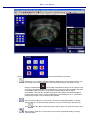
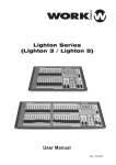
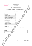
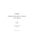
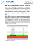
1
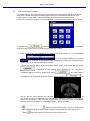
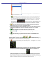
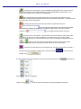
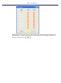
BioJet - User Manual 1.1. The General Biopsy Functions Tracking and locating biopsy positions as well as assigning the lab results to the respective biopsies will help in focal therapy and general therapy. For this reason Encage Target Plus allows the user to plan the required biopsies. It is advantageous to use a tracking stepper in this case. The biopsy functions are located: On Regsiter Card: In the Drop-down menu: On the toolbar the Icons: and The meanings of the icons are: o : Select biopsy needle type by biopsy core length from the list: o : Display Biopsy Report o : Display Biopsy Data Form o or : Show or hide drawn tumor areas o or : Show or hide all biopsy guides and biopsy positions o or : Show or hide unused biopsy needles o or : Show or hide non-malignant biopsies In order to use the biopsy functions calibrated ultrasound images must have been collected as described above. It is then advantages to draw in the required organ contours (see chapter “Drawing Organ Contours into Ultrasound Images and other Image Types”). After that has been completed swith to the register card . That register card includes all required biopsy functions as well as the fuctions required to draw recognized tumor areas into the images. BioJet - User Manual The box o lists the required biopsy functions: : Determin the x, y-position of a planned biopsy guide line by selecting this function and the clicking at the required position in the main image window. The position in the image is marked with a . The number designates the biopsy to be acquired. Only one biopsy per guide position can be acquired. A right mouse click will delete that mark. Until actual biopsies have been acquired the biopsy positions will renumber automatically. After that the numbers will always count upward and deleted positions numbers will not be reused. Thus it is advatagious to first definy all the x, y-position for all biopsies planned. Up to 50 biopsies are possible. o : Move a biopsy guide line. This function only works in longitudinal display on biopsy guide positions. If a planned biopsy postion is to be move somewhere else then fist click o and the delete a planned position and the place the guide somewhere else. : Bend a biopsy guide line. This function only works in longitudinal display on biopsy guide positions. BioJet - User Manual o : Place a biopsy core, i.e. complete a biopsy. The poison of the core defines the exact position in x-, y-, z-coordinates from which the biopsy sample was taken. The position is marked as in the main image. A yellow color markes the sample as undefined at the time. o : After the biopsy samples have been analyized the bioipsy cores can only be benign or malignate. By clicking the biopsy mark it will change its color to to designate a benign sample. In order to go back to undefined just click the mark again with a right mouse click. o : After the biopsy samples have been analyized the bioipsy cores can only be benign or malignate. By clicking the biopsy mark it will change its color to to designate a malignate sample. In order to go back to undefined just click the mark again with a right mouse click. o :If tumors haved been drawn into the images they can all be removed at once after a prompt if this icon is clicked. o :This function will delete all unused biopsy guide lines. After the biopsies have been taken the user can click the tool results: and display all the biopsy The Biopsy Number is unique and cannot be changed as it points to the repective biopsy core. If a biopsy guide line was placed but no biopsy taken that line number will not be listed. The core length is the length choosen from the list accessable by clicking in the toolbar. The numbers under x, y, and z represent the center of the biopsy core taken. The origin is the central bottom point on the general template (see chapter “Calibrating the General Template to the Ultrasound Device und thus the Ultrasound Images”). These numbers cannot be changed. All other entries are user selectable. This table will be transferred to the Biopsy Report. The table allows a simple entry of laboratory data. By clicking on in the column the type of tissue can be selected BioJet - User Manual from . The Gleason score may also be selected from a list remaining data can be marked as by clicking the reseptive box . The entries that can be marked as positive are: - PCI: Prostate Capsular Infraction - PNI: Peri-Nervous Invasion - ASAP: Atypical Small Acinar Proliferation - PIN: Prostatic Intra-Epithelial Neoplasia . The BioJet - User Manual 1.2. The Longitudinal Image Display on Register Card Biopsy In order to access the longitudinal display just click card on register . The display changes to: In this case 6 biopsy guide line have been positioned. To return to the transverse display click . The box o lists the available biopsy functions: : Determine the x, y-position of a planned biopsy guide line by selecting this function and the clicking at the required position in the main image window. The position in the BioJet - User Manual image is marked with a . The number designates the biopsy to be acquired. Only one biopsy per guide position can be acquired. A right mouse click will delete that mark. Until actual biopsies have been acquired the biopsy positions will renumber automatically. After that the numbers will always count upward and deleted positions numbers will not be reused. Thus it is advantageous to first define all the x, yposition for all biopsies planned. Up to 50 biopsies are possible. o : Move a biopsy guide line. This function only works in longitudinal display on biopsy guide line positions. If a planned biopsy position is to be moved somewhere else then move the mouse pointer to the required guide line and hold the left mouse button down. A blue line will then appear. Move the blue line to the desired position and the release the mouse button. Then yellow guide line will then jump to the position of the blue line. In case as biopsy has been taken a blue box will appear and the functions works accordingly. o : Bend a biopsy guide line. This function only works in longitudinal display on biopsy guide line positions. If a planned biopsy position is to be bent somewhere then move the mouse pointer to the required guide line and hold the left mouse button down. A blue line will then appear. Move the blue line to the desired position and the release the mouse button. Then yellow guide line will then jump to the position of the blue line. In case as biopsy has been taken a blue box will appear and the functions works accordingly. o : Place a biopsy core, i.e. complete a biopsy. The poison of the core defines the exact position in x-, y-, z-coordinates from which the biopsy sample was taken. The position is marked as in the main image. A yellow color marks the sample as undefined at the time. After moving to the next biopsy the guide line disappears . If the core graphic is in the wrong position just left click the mouse somewhere else along the guide line and the core will move accordingly. If the core is to be removed then just click on the core with the right mouse button held down. o : After the biopsy samples have been analyzed the biopsy cores can only be benign or malignant. By clicking the biopsy mark it will change its color to to designate a benign sample. In order to go back to undefined just click the mark again with a right mouse click. BioJet - User Manual o : After the biopsy samples have been analyzed the biopsy cores can only be benign or malignant. By clicking the biopsy mark it will change its color to to designate a malignant sample. In order to go back to undefined just click the mark again with a right mouse click. o :If tumors have been drawn into the images they can all be removed at once after a prompt if this icon is clicked. o :This function will delete all unused biopsy guide lines. BioJet - User Manual 1.3. The Tumor Draw Function If recognized tumors may be drawn into the image stack in the same way as the other structures were drawn. Please see chapter “Drawing Organ Contours into Ultrasound Images and other Image Types” for more details. Only the items that are different will be explained here. In this case 10 Tumors numbered 1 to 10 may be drawn. The tumor draw functions can be found on register card in the box: of the icons are the same as in of drawing organ structures. In short: . The meaning Draw functions are only available if the image in the main window is a non-interpolated image: , i.e. if the number between the brackets is not 0.00 then an interpolated image is displayed in the Encage Target Plus main window and not all draw functions are accessible. Tumors can only be drawn in the transverse image mode. That means that the button is displayed on this register page. Contours can be corrected in longitudinal display as well by clicking then button now displayed in longitudinal projection and the button changes to . The image stack is . On the top right the angle selection box appears: . As long as the image is not switched to live video display additional calibration is not required. This is only necessary in case the image is switched to live. How this is done is explained in chapter “Correcting Contours in Longitudinal Display” – please see there. o : This is the tumor select function. The tumor visible in the box is the one that can be draw, copied, pasted or interpolated at the time being. After clicking select the structure to be drawn from the selection box BioJet - User Manual . The structures setup function is described below. The names are user definable. o After clicking this icon the selected tumor contour can be drawn (draw mode) with the mouse by moving the mouse while holding down the left mouse button at the same time. Alternatively, the contour is also drawn by clicking individual points on the selected organ contour. As soon as the cursor gets near the position from where the organ was drawn a doted line shows how the contour will be completed. If the proposal is correct just let go of the left mouse button and the organ is auto-completed. o is the quick draw function. By clicking a few points on an tumor contour and then double clicking at the end a contour is automatically entered. . o The volumes of the tumors drawn are displayed in the box above. The volume is constantly updated as soon as the tumor contours on other image planes have been completed. o After clicking this icon (or pressing [Ctrl] [C]) the contour selected in on the image plane within the main Encage Target Plus is copied. o After clicking this icon (or pressing [Ctrl] [V]) the stored contour is pasted into the image in the main Encage Target Plus window at the same position from which it was copied. Pressing the [Page ] or [Page ]-key while , , or is selected will result in transferring the selected contour to the next thumbnail image. This is equivalent to pressing [Ctrl] [C], then clicking the next thumbnail and then pressing [Ctrl] [V]. o This is the “rubber banding” tool. After clicking the icon, points appear on all contours . These points are the “supports” of the drawn contours. The mouse may be moved to any contour support point. As soon as the cursor “sees” the contour it will change from an arrow to a hand with a pointed finger. By depressing the left mouse button on a support point the points on the contour change to . By moving the mouse with the left mouse button pressed the contour will follow the mouse movement. By moving one of the red squares, the shape of the contour will change accordingly. A support point may be deleted by clicking the desired point with the right mouse button. Alternatively, points may be added by clicking the desired contour position with the left mouse button. BioJet - User Manual o If a contour has been drawn on two nonadjacent image planes, the contours of the selected structures on the images between the ones already drawn will be filled in. The position and shapes of the contours are interpolated. o After clicking this tool the organ structures can be moved. The mouse must be positioned on the structure borderline and the left mouse button held down. The structure will then follow the mouse movements. o By clicking this tool with the left mouse button the selected structure in on the image plane displayed in the main Encage Target Plus window is deleted. By clicking this tool with the right mouse button the selected structure in o on all image planes are after a prompt . This is the undo / redo button. The last action can be reversed by clicking the undo / redo button. As soon as an action pertaining to one plane only such as draw, rubber banding, delete structures, or others have be done, the icon changes its appearance from to if the function has not been used before. A second click on the button reverses the change back to the start case before the first click on the button. o :If tumors have been drawn into the images they can all be removed at once after a prompt if this icon is clicked. This function is found in the box register card . In order to define the Tumor names and colors go to the drop-down menu menu After clicking at the top of the and then the appears. with the left mouse button the following dialog box pops up: BioJet - User Manual All data displayed in this menu can be stored as default (see chapter “Storing / Loading Structure Data (Preset)“). To change anything just click on the respective box and change accordingly. To store any changes just click . BioJet - User Manual 1.4. The Biopsy Report The biopsy report is accessible after clicking in the toolbar. The report will appear in its own window. An additional menu is at the top of the window having the following functions, that can be clicked on. :Show or hide the document map : Go to first page : One page backward : One page forward : Go to last page : Refresh : Print report – After clicking this function a specials printer menu pops up. The menu depends on the printer used. : Switches the page layout : Printer page layout - After clicking this function a specials printer menu pops up. The menu depends on the printer used. : Export the report either to MS Excel or create a PDF file. This can be selected from a drop-down menu After clicking and selecting EXCEL or PDF the box appears: . Please store the data where required. To open the data file please open EXCEL first and then import the file. : The size of the display can be selected here. If this function is clicked the size can also be selected with the mouse wheel : After typing in a word, that word is searched for after clicking The following data is at the top of all report pages: BioJet - User Manual - Name of the hospital and the department - Patient name - Treatment date and time - Name of the treatment plan The first page includes the patient and study data. The second page (possibly more pages are required to display all results) displays the biopsy positions and data on the core lengths. BioJet - User Manual The third page (possibly more pages are required to display all results) displays the biopsy results entered into the biopsy after clicking details. in the toolbar. See chapter “The General Biopsy Functions” for more BioJet - User Manual The last pages display the images including all contours and other items drawn into the images.