1
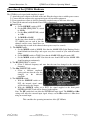
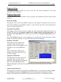
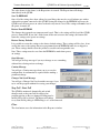
Vancura Innovations Co.
Imagination is more important than knowledge … until you have to build what you’ve imagined.
QT100A
Quad Tone Generator
And
Channel Marker
QT100 User Manual
&
Software Operating Manual
Version 1.00.01
11/8/2004
Prepared by
Vancura Innovations Co.
9010 33rd Street West
Rock Island, IL 61201
(309) 756-0769
Email: [email protected]
http://vancura-innovations.com
Vancura Innovations, Co.
QT100 User & Software Operating Manual
11/8/2004
Table of Contents
Product Description.........................................3
Optional software:......................................3
Optional hardware: ....................................3
Operation of the QT100A Hardware...............4
Theory of Operation........................................5
Specifications ..................................................5
Software Installation .......................................6
USB Configuration .........................................6
Connecting the Hardware ..........................6
Program Setup.................................................7
Program Operation ..........................................7
Program startup..........................................7
Override Front Panel..................................7
Frequency Select Box...........................7
Output Level Select Box ......................7
Output Control Select Box ...................7
Use External Source .............................8
Use Front Panel Button ........................8
Calibrate .................................................... 8
Tone Hz................................................ 8
Amplitude ............................................ 8
Mark Time ........................................... 8
Repeat .................................................. 8
Save To EEPROM ............................... 9
Restore From EEPROM ...................... 9
Restore Factory Defaults ..................... 9
Oops Message ...................................... 9
Caution Message.................................. 9
Changes Not Saved Message............... 9
Stop Poll - Start Poll.................................. 9
Clear .......................................................... 9
Miscellaneous.......................................... 10
Device ID ........................................... 10
Product ID & Vendor ID ................... 10
Model & Version ............................... 10
ROM Addr ......................................... 10
It is presumed that the reader of this manual is familiar with PC computers and knows how to use the Windows operating
system that will be running this software. The administrator of this machine/software may be required to set up a network
connection, install programs, move files, edit text files, and run programs. This set of programs may be used as standalone or in conjunction with external hardware. Setup may be used to assign ID numbers and network information.
The end operator should be able to read numbers and simple text. The operator may need to understand how to use a
touch screen without damaging it.
This manual is the property of Vancura Innovations and has been published for the exclusive use of it
customers. No portion of this manual may be reproduced without the explicit consent of Vancura
Innovations. This manual may contain proprietary information, and may not be distributed to anyone
outside of the company.
9010 33rd Street West
Rock Island, IL 61201
(309) 756-0769
Email: [email protected]
http://vancura-innovations.com
Page 2
Vancura Innovations, Co.
QT100 User & Software Operating Manual
11/8/2004
Product Description
The QT100A Quad Tone Generator and Channel Marker is a microprocessor-controlled device
designed to provide identical outputs to four channels of audio. A distinct marker chirp can be added
to each channel for identifying and tracing purposes.
The QT100A front panel allows the operator to:
1) Select one of three frequencies, Default: 250, 400, and 1000 Hz
2) Select one of three amplitudes, Default: 0, 4, and 8 dBu
3) Turn channel makers ON or OFF,
4) Turn the TONE ON or OFF
5) Select INTERNAL or EXTERNAL tone source,
6) Connect an EXTERNAL audio source through a standard XLR female connector
7) Turn QT100 ON/OFF
8) Connect to an optional PC support program through a Universal Serial Bus (USB) connection
The QT100A back panel has:
1) Four standard XLR male connectors for connection to your audio system, and
2) A power jack for 12VDC or 9VAC to 12VAC @ 200ma.
The channel marker mode injects a distinct no-tone chirp on each of the channels. Channel one has a
single chirp, channel two has two chirps, channel three has three chirps, and channel four has four
chirps. All four channels chirp in tandem, that is, the first chirp is heard on all four channels; the
second chirp is heard on channels 2, 3, and 4; the third chirp is heard on channels 3, and 4; and the
fourth is heard only on channel 4.
Optional software:
The optional PC based support program allows the operator several additional functions. The support
program will allow:
1) Complete computer remote operation of the QT100A.
2) Selection of one of five preset frequencies, Default: 60, 250, 400, 1000, and 2000 Hz
3) Selection of one of five preset Amplitudes. Default: -10, 0, 2, 4, and 8 dBu
4) Select TONE, OFF, MARK, and SWEEP modes
5) Calibrate/change any of the preset frequencies. Range: 0.715 Hz to 7.8 KHz
6) Calibrate/change any of the preset amplitudes. Range: – 32 dBu to 8 dBu in 99 steps
7) Modify the front panel switch preset frequencies and amplitudes.
8) Modify the marker repeat rate from 0.067 to 16.8 seconds.
9) Modify the marker chirp size and spacing from 0.033 to 8.3 seconds.
10) Restore factory default settings or last saved calibration settings.
11) Save any changes/calibrations so that the QT100A can be operated with the new power-on
settings without the support program.
Optional hardware:
To use the optional software, a USB-A to USB-B cable is needed to connect between the computer
and the QT100A. This is not normally supplied with either the QT100 or the Optional Software. This
cable is fairly standard and can be purchased from a variety of electronics and office supply stores. It
may also be purchased directly from Vancura Innovations for $9.95 plus shipping.
9010 33rd Street West
Rock Island, IL 61201
(309) 756-0769
Email: [email protected]
http://vancura-innovations.com
Page 3
Vancura Innovations, Co.
QT100 User & Software Operating Manual
11/8/2004
Operation of the QT100A Hardware
The QT100A was designed with simplicity in mind.
1) Attach the power adapter to the back of the unit. Plug the adapter into a suitable power source.
2) Connect the four outputs to the appropriate inputs on your audio equipment.
3) If an external tone source is desired, connect the external source to the front of the unit.
4) Turn ON the unit and verify that the Power LED is illuminated.
Initial Setup:
a. Set the SOURCE switch to INT.
b. Set the HZ (FREQUENCY) switch
to 400 Hz.
c. Set the dBu (AMPLITUDE) switch
to 4 dBu.
d. Set MODE to MARK.
At this time, there should be a 4 dBu (0VU) 400 Hz tone on each of the four
channels and the tones should have an
identifying chip on each of the channels that repeats every five seconds.
5) The MODE switch:
a. Set the MODE switch to MARK. Note that the MARK LED (Light Emitting Diode)
should blink four short blips and repeat every five seconds in sync with the marker
chirps.
b. Set the MODE switch to TONE. Note that the MARK LED should remain OFF.
c. Set the MODE switch to OFF. Note that the tone should OFF and the MARK LED
should remain on continuously.
6) The HZ (FREQUENCY) switch:
a. Select a different frequency and note that the tone has changed to the indicated
frequency.
7) The dBu (AMPLITUDE) switch:
a. Select a different amplitude
setting and note that the tone has
changed
to
the
indicated
amplitude.
8) The SOURCE switch:
a. With the SOURCE switch set to
INT, the internal signal source
will be directed to the outputs.
b. With the SOURCE switch set to EXT, the signal supplied to the front panel
EXTERNAL INPUT jack will be directed to the outputs.
Note: The HZ switch does not affect the EXTERNAL input signal. The MODE and dBu
settings will affect the external input signal. Always set the dBu switch to 8 dBu when
using an external input.
This concludes the operating instructions of the QT-100 unit.
9010 33rd Street West
Rock Island, IL 61201
(309) 756-0769
Email: [email protected]
http://vancura-innovations.com
Page 4
Vancura Innovations, Co.
QT100 User & Software Operating Manual
11/8/2004
Theory of Operation
The QT-100 is a microprocessor-controlled device that operates from a 12 MHZ crystal and
performs all of the control functions.
Tone frequency generation is accomplished by setting a timer in the processor to output a clock
128 times the desired frequency. The clock output is divided by 2 and then by 64 to generate a
square wave at the desired tone frequency. Both frequencies (the fundamental and 64 X
fundamental) are input to an 8 pole digital Bessel filter. The digital filter strips off all of the
harmonics and outputs a 64-step sign wave. The amplitude of this tone is constant over the entire
audio frequency range.
Amplitude control is accomplished by using a 100 position digital variable resistor. The resistor is
set at maximum (100%) and the output is calibrated to 8 dBu. The other calibrated amplitudes are
achieved by adjusting the resistor setting to the appropriate value for the selected amplitude.
Tone marking timing is accomplished by setting a second timer for each of the intervals. The
actual chirp is the result of setting the digital amplitude resistors to zero at the appropriate times.
The External input is buffered into a 600-Ohm differential amplifier. The signal is switched to the
input of the marking circuit and then to the four 600-Ohm balanced output buffer amplifiers.
The Microprocessor has a built-in USB interface, which is used to both program the processor
and to calibrate all of the settings. The Processor program is stored in an EEPROM memory chip.
A separate location, in the EEPROM, is used to store all of the calibration parameters. The
program and these parameters are loaded each time the QT100 is turned on.
Specifications
•
Input Current: 200ma Maximum.
•
Input Voltage: 12VDC or 9VAC to 12VAC 50/60Hz. Connector 2.1mm X 5.5mm X 11mm (inner x outer
diameter x Length)
•
Input power adapter: 120VAC converter to 12VDC @ 200 ma.
•
Temperature: 0 deg C to 50 deg C (32 F to 125 F) non condensing
•
Size L X W X H: 185mm x 107mm x 60mm (7.25in x 4.22in x 2.4in). Handsome black anodized
aluminum box with yellow text that won'
t rub off.
•
Universal Serial Bus (USB) Interface: Standard USB-B interface. For connection to PC and optional
customizing program. Interface is USB 1.0 compliant
•
Audio: Single audio tone from internal or external source sent to all four channels after passing through
marker controller.
•
Tone: Internal audio tone is created from a crystal controlled square wave filtered with an 8 pole Bessel
digital filter sampled at 64 times the fundamental frequency. The third harmonic is attenuated more than
60 dB. Tone can be adjusted from 60 Hz to 7812 Hz.
•
Amplitude: Maximum usable amplitude internal or external is 8 dBu. Internal amplitude digitally
adjustable in 100 steps from 1.9456 volts (8 dBu) to 0 volts.
•
Marking: Marking is 200ms Tone-OFF separated by 200ms Tone-ON repeated times the channel number.
Sequence is repeated every five seconds. Customizing program can change this in 33 ms steps.
9010 33rd Street West
Rock Island, IL 61201
(309) 756-0769
Email: [email protected]
http://vancura-innovations.com
Page 5
Vancura Innovations, Co.
QT100 User & Software Operating Manual
11/8/2004
Software Installation
Installation of the program is straightforward:
1) Turn ON the computer and login as an administrator.
2) Insert the CD into the CDROM drive. The program installer should run automatically. If not
follow the next 2 steps.
a. From the desktop, select the windows explorer program and click on the CDROM drive
icon
b. Select setup.exe and double-click on it. This will start the install program.
3) If you get an error concerning the latest windows installer, click OK and ignore it
4) Product Installation Window: Click Next
5) License Window: Select the “I accept” button and click Next
6) Customer information Window: Change the information as desired and click Next
7) Ready to Install Program Window: click Install
8) Install Wizard Screen: click Finish
The program is now installed and should be ready to run. You should note a new Icon on the desktop
screen. Click this Icon to start the program. The icon may be deleted or moved if you don’t want it on
the Desktop
USB Configuration
The QT100 hardware communicates with the software through a USB port. The proper driver must
be installed for it to work.
1) Connect the USB cable to the computer and connect it to the powered-up QT100.
2) The computer should recognize the USB device and ask for a driver for it.
3) Select the CDROM and point to the Driver directory on the CDROM to complete the
installation.
4) At this point, the installed software should be able to recognize QT100.
Connecting the Hardware
To connect the QT100 to the computer use a standard USB-A to USB-B cable. If you don’t have a
cable, one can be purchased from Vancura Innovations. Either cable end may be connected first and
both the computer and the QT100 may be ON or OFF when connecting them. After connecting the
cable, make sure both the computer and the QT100 are plugged in and turned ON.
If the QT100 drivers had not been previously installed, the computer should recognize that new
hardware has been added and will ask you to install drivers for it. Install the CD/ROM disk and direct
the installer to the Drivers directory on the CD.
9010 33rd Street West
Rock Island, IL 61201
(309) 756-0769
Email: [email protected]
http://vancura-innovations.com
Page 6
Vancura Innovations, Co.
QT100 User & Software Operating Manual
11/8/2004
Program Setup
The program should not require any special setup. The only special requirement is the proper
installation of the USB driver.
Program Operation
The program must be installed before it can be operated. See installation section if it has not been
installed.
Program startup
The program scans for all of the QT100’s connected to the computer and attaches to the first one it
finds. After attaching to the QT100, it requests a status from the unit and uses the information to
show the settings currently in use.
Override Front Panel
The program will not let the operator to change any of the front panel setting unless this box is
checked. The three boxes Frequency, Output Level, Output Control, Use External Source, and
the Button Use Front Panel will remain grayed out until the Override Front Panel mode is
checked.
Note: The QT100 front panel is never disabled in the override mode. If any front panel switch is
changed, it will take precedence over any prior changes made at the computer.
Frequency Select Box
The frequency select box allows the
operator to select one of five preset
frequencies. Three of the frequencies will
match those seen on the QT100 front
panel.
When modifying the calibration of a
frequency, the selected item will be the
one that is changed.
Output Level Select Box
The Output Level select box allows the
operator to select one of five preset
amplitudes. Three of the levels will match
those seen on the QT100 front panel.
When modifying the calibration of an amplitude level, the selected item will be the one that is
changed.
Output Control Select Box
The operator may remotely select the Mode used. Tone outputs a solid tone with no marking. Silent
turns OFF the tone completely. Marker turns ON the tone and injects marker chirps for each
channel. These functions are identical to the front panel switch. There is an additional selection:
9010 33rd Street West
Rock Island, IL 61201
(309) 756-0769
Email: [email protected]
http://vancura-innovations.com
Page 7
Vancura Innovations, Co.
QT100 User & Software Operating Manual
11/8/2004
Sweep. Selecting Sweep will cause the frequency output to sweep from a low starting frequency to an
ending high frequency. The default lower frequency is 180 Hz and the upper frequency is 5200 Hz.
The default sweep rate is 0.033 sec. per tone and sweeps through 255 frequencies, taking 8.4 seconds.
Marking may be ON or OFF while sweeping. Selecting Tone, Mark, OFF, or EXT will stop the
sweep and hold on the current frequency. Select a frequency from the screen or toggle the frequency
switch to return to a standard frequency.
Use External Source
The Use External Source check box will activate the QT100 to transfer the outputs to an external
source signal. The external signal is to be provided through the front panel XLR connector. The dBu
level switch should be in the 8dBu (UP) position to assure proper amplitude pass-through while
using the external source.
Use Front Panel Button
The Use Front Panel button will instruct the QT100 to read the front panel switches and set the
output accordingly.
Calibrate
The calibrate feature allows the operator to configure the QT100 to the their preferred configuration.
The changes can be temporary, or saved indefinitely for regular use.
Tone Hz
Select this button to allow changing the selected frequency from its current value. Click or Click and
Hold the UP or the DN button to change the value. Since the frequency is referenced to a crystal
clock, the exact value is displayed next to the selected frequency button. The frequency will change
immediately in the QT100.
Amplitude
Select this button to allow changing the selected Amplitude from its current value. Click or Click
and Hold the UP or the DN button to change the value. The amplitude is referenced to 8 dBu or
1.94569 volts. The second number next to the amplitude button is the percent of full-scale volts that
is being sent to the outputs. The amplitude will change immediately in the QT100. Note: the 8 dBu
level should always be left at maximum value, 100%, especially if you plan to use external input
signals.
Mark Time
The Mark time is the chirp interval, the time that the tone is OFF. On channels 2, 3, and 4, it is also
the intra-Mark (tone-ON) time between the chirps. If the Mark time were set to 0.20 seconds and the
repeat time set to 5 seconds, the channel two tone sequence would be: 0.2 sec OFF, 0.2 sec ON, 0.2
sec OFF, 4.4 sec ON, and then repeat. This time can be adjusted from 0.033 seconds to 8.4 seconds.
The value shown in the frame is in seconds. The Mark and intra-Mark times will change
immediately in the QT100.
Repeat
The Repeat time is the chirp cycle time. If this value were set to 5 seconds, the channel chirps would
repeat every 5 seconds. Repeat adjusts the interval time, the time between the end of one set of chirps
and the beginning of the next set. The repeat time is the sum of four Mark times, four intra Mark
times, and the interval time. The interval time can be adjusted from 0.067 seconds to 16.8 seconds.
9010 33rd Street West
Rock Island, IL 61201
(309) 756-0769
Email: [email protected]
http://vancura-innovations.com
Page 8
Vancura Innovations, Co.
QT100 User & Software Operating Manual
11/8/2004
The value shown, in the frame, is the Repeat time in seconds. The Repeat time will change
immediately in the QT100.
Save To EEPROM
Once all of the settings have been adjusted to your liking, they may be saved for future use with or
without this program connected to the QT100. Storing the changes to the EEPROM will cause the
QT100 to use the new power-on values each and every time it is used. The settings will not be lost if
the power is turned off.
Restore From EEPROM
The changes that you make are temporary until saved. That is, the settings will be lost if the QT100
power is turned OFF. If you don’t wish to turn off the unit to restore the settings, this button will
return the settings to the power-on settings.
Restore Factory Defaults
It is possible to restore the settings to the factory default settings. These settings will be close, if not
exactly the same as the settings that were programmed into the EEPROM when it was shipped to
you. These settings should restore the product to a usable and recognizable state.
Note: These settings must be saved into the EEPROM to make them poweron settings.
Oops Message
You will get an Oops message if you try to change or save something
without first selecting an item to change.
Caution Message
You will get a Caution message when you try to save the
configuration. A confirmation is required before making a
permanent change.
Changes Not Saved Message
You will get a Changes Not Saved reminder message if you
try to exit the program without first saving your changes.
Stop Poll - Start Poll
The QT100 is monitored dynamically and switch
changes made on the panel will be reflected on
program window as they are changed. Polling may be
turned OFF or ON as desired. The button will change
to say Start Poll if polling is OFF Polling is at 1-second intervals.
Clear
The clear button erases the information in the Response window.
9010 33rd Street West
Rock Island, IL 61201
(309) 756-0769
Email: [email protected]
http://vancura-innovations.com
Page 9
Vancura Innovations, Co.
QT100 User & Software Operating Manual
11/8/2004
Miscellaneous
Device ID
The Device ID is the USB device ID. It will usually read EZUSB-0. If more than one QT100 device
is connected to the computer, the program will find and list then all. The sequence number will be in
the order they are attached to the computer.
If the USB connection is lost and restored in less than 10 seconds, the restored connection may have a
different sequence number.
Product ID & Vendor ID
Product ID and Vendor ID are USB diagnostic values and are checked to make sure the program is
accessing the right product.
Model & Version
Model and Version are the model number of the QT100 device and the Version Is the software
version running on the QT100.
ROM Addr
The ROM address is the starting location of the settings stored in the EEPROM of the QT100.
- Finis -
9010 33rd Street West
Rock Island, IL 61201
(309) 756-0769
Email: [email protected]
http://vancura-innovations.com
Page 10