1
RF_Sub1GHz_mod_USB_SRM
Board v0.3
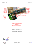
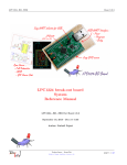
Fig 4 – Module Connectors
3.2.1
P1 Connector
P1 is a male USB-A port.
Refer to the Universal Serial Bus (USB) 3 page on Wikipedia for pinout and more information on the USB bus and
connectors.
3.2.2
P2 Connector
Pin #
1
2
Fig 5 – P2 Connector
Description
GND : Ground
+Vin : External unregulated input, +0.9V to
+3.6V
LPC Pin
-
Table 2 – P2 Connector Pinout
P2 connector is a standard 2.54mm (0.1 inch) pitch header, with 2 pins, and can be populated using either male
or female header, and mounted either on top or on bottom of the board.
P1 connector provides access to +Vin and Ground for the onboard step-up regulator. This lets you power the board
using a large variety of power sources.
Note : it is also possible to power the board from +4.2V LiPo batteries, though this is not recommended
without the use of an LDO or step down regulator.
3. http://fr.wikipedia.org/wiki/Universal_Serial_Bus
Techno-Innov - DomoTab
http://www.techno-innov.fr
page 6 / 26