1
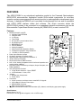
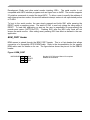
Reset Switch
The RESET switch provides an asynchronous reset input to the MCU. Pressing the RESET
switch produces a low-voltage level on the RESET input to the MCU. The low-voltage
supervisor (LV1) holds the RESET line low for approximately 150 ms after the pushbutton is
released.
Low-Voltage Detect
A DS1813 (LV1) provides POR, low-voltage detect, and pushbutton reset services for the
module. At power-on, LV1 holds the MCU in reset for 150 ms after VCC reaches approximately
4.35V. During normal operation, LV1 asserts RESET when VCC falls below 4.35V and holds
RESET true for 150 ms after VCC returns to normal. The push-button operation is described
in the paragraph above. Use of connector J1 to supply +3.3V to the module requires disabling
LV1.
LV1 may be disabled by opening the cut-trace CT1. Simply remove the circuit trace between
the cut-trace pads to open the circuit. To restore the circuit functionality, install a 1206 size, 0ohm, resistor or a short piece of wire across the cut-trace pads.
Timing
A ceramic resonator (Y1) provides a 16.0 MHz base operating frequency to the MCU. This
supports a default 8.0 MHz internal operating frequency. Higher frequencies are possible
using the embedded PLL. The resonator output is routed to the MCU only and is not available
at the MCU Port connector (J1). The MCU ECLK output is available to the user at connector
J1 if enabled.
Communications
The APS12C32SLK module provides a single RS-232 communications port. An RS-232
transceiver (U2) provides RS-232 signal level to TTL/CMOS logic level translation. RS232
signals TXD and RXD are routed between the transceiver and the MCU. These signals are
also routed to connector J1. RS-232 communication signals input on J1 must be TTL/CMOS
logic levels; no translation support is provided through this path. The transceiver output may
also be driven off-module if the signals are suitably buffered. As added development support,
hardware flow control signals RTS and CTS are available on the logic side of U2. These
signals are routed to vias located near the transceiver (U2). RTS has been biased properly to
support 2-wire RS-232 communications.
Freescale Semiconductor
9