1
PINTASTIC V2.0 USER MANUAL
1- PRODUCT OVERVIEW:
The PINTASTIC interface board is a simple to use phone PIN printing solution. Featuring one time pin use
safeguarding to ensure each pin is used only once. Easily print phone PINs stored in two easy to replace 8
pin IC’s. PINTASTIC can print 10 or 12 digit phone pins in quantities of 5000, 10000 or 20000. The
PINTASTIC utilizes pulses to print a ticket, making it compatible with any amusement or vending machine
that utilizes a pulse signal input/output. The PINTASTIC can be used in stand alone systems or integrated
systems using a shared printer. Shared printer mode utilizes serial input or a pulse input from a secondary
source to print a ticket. PINTASTIC also includes options to customize your printed PIN ticket, all of which
are dip switch adjustable. Connections are also available for hard meters. IT’S SIMPLY PINTASTIC!!
2 - COMPATIBLE PRITERS:
•
•
•
ICT GP58-CR
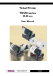
Custom TG558
CITIZEN 3551
3 – SHARED PRITER MODE:
This feature allows the PINTASTIC interface board to share a printer with either a serial out or pulse out
game board. Default operation is in pulse mode.
Pulse mode will accept pulses in and print the number of pulses on a ticket. In pulse mode the ticket format
is not adjustable. All printers can be used with default settings. Meter out is used to keep track of all pulses
counted on this input.
Serial mode will accept serial in from Pot of Gold games. In serial mode the ticket format is set within the
Pot of Gold game. Serial mode requires that each printer be set to a baud rate of 2400 in order to operate
correctly with the PINTASTIC interface board.
4 - LED IDICATORS:
There are 3 LED indicators located on the PINTASTIC interface board. Each LED performs a different
function and will be on or off depending on the current status of the interface board.
PWR (green) – Used to indicate power is being supplied to the PINTASTIC interface board. The LED will
be on as long as there is power.
MC1 (red) – Used to monitor the status of controller MC1 on the PINTASTIC interface board. This LED
will be on or off periodically depending on what function the controller is performing at the time. During
normal idle operation MC1 LED will be off.
MC2 (red) - Used to monitor the status of controller MC2 on the PINTASTIC interface board. This LED
will be on or off periodically depending on what function the controller is performing at the time. During
normal idle operation MC2 LED will be flashing on/off.
Page 1 of 5
PINTASTIC V2.0 USER MANUAL
5 – METERS:
The PINTASTIC gives you the ability to have a source of book keeping using hard meters.
METER IN – used as a way to record the amount of coin in received by PINTASTIC.
METER OUT – used as a way to record the amount of cash out received by PINTASTIC.
6 - COECTORS:
J1
Pin 1 - +12 VDC (ORANGE)
Pin 2 - Gnd (BLACK)
Pin 3 - Meter in (GREEN)
Pin 4 - Meter out (BLUE)
J2
Pin 1 - Bill acceptor disable (BROWN)
Pin 2 - +5 volts (RED)
Pin 3 - Pulse in – ticket out (WHITE)
Pin 4 - Pulse in – coin in (GREY)
PULSE I – TICKET OUT
Signal in to print cash out ticket. Pin 28, parts side, with 8 liner harness and pin 8, solder side, with POG
harness.
PULSE I – COI I
Signal in to print phone pins. Pin 23, parts side with 8 liner harness and pin 8 parts side with POG harness.
SERIAL I
Serial input operating at 2400 baud, 8,N,1. This connection is compatible with Pot Of Gold games by simply
using a straight through network cable. When using this connection shared printer mode must be set to
serial.
TO PRITER
This connector is used to attach the printer to the PINTASTIC interface board. Use the following
instructions to connect a compatible printer.
• ICT GP58-CR – Use supplied green cable, connect side marked ‘printer’ to ICT printer. ICT printer
must be in “Pot of Gold mode” to operate correctly with the PINTASTIC interface board. Only ICT
printers with “Pot of Gold mode” selectable by dip switch 4 on the printer will work with the
PINTASTIC interface board. Turn dip switch 4 ON to enable “Pot of Gold mode.”
• Custom TG558 – use supplied green cable, connect side marked ‘printer’ to Custom TG558 printer.
The PINTASTIC interface board operates with Custom TG558 factory printer settings.
• CITIZEN 3551 – use supplied cable, connect DB25 pin connector to CITIZEN 3551 printer. The
PINTASTIC interface board operates with CITIZEN 3551 factory printer settings.
*NOTES:
1. Unused wires on connector J1 or J2 should be individually capped so they do not cause any
interference with other electrical components. DO NOT TIE UNUSED WIRES TOGETHER.
2. Meter in and meter out are designed to be used with 12 volt DC, 2 wire counters. Connect positive
wire of counter to +12 volts DC and the negative wire of counter to J1 pin 3 or J1 pin 4.
3. This note applies ONLY when using Pyramid Technology bill acceptors. When using Pyramid
Technology bill acceptors, use pin 1 (brown wire) of the 18 pin connector on the bill acceptor.
Connect pin 1 from bill acceptor to J2 pin 4 of PINTASTIC interface board input connector.
Page 2 of 5
PINTASTIC V2.0 USER MANUAL
4. Bill acceptor disable is an active low output from PINTASTIC used to disable a bill acceptor. This
only disables the bill acceptor when pulses are detected on J2 pin 3. To ensure correct operation, the
bill acceptor disable should be used when using this pulse input in shared printer mode.
7 - OPERATIG ISRUCTIOS:
• Make proper electrical connections with supplied input harness.
• Connect printer using supplied cable, making sure to install according to markings.
• Install two 8 pin IC’s containing phone PINs. When new IC’s are being installed for the 1st time
please refer to section 8 - INSTALLING NEW PHONE PIN IC CHIPS
• Turn on power
• Wait a couple seconds and a power up ticket will be printed displaying current settings & PINs
remaining.
• PINTASTIC is ready to use!
8 - ISTALLIG EW PHOE PI IC CHIPS:
•
•
•
•
Insert 8 pin IC marked ‘L’ or ‘LOW’ in to IC socket labeled ‘LOW’
Insert 8 pin IC marked ‘H’ or ‘HIGH’ in to IC socket labeled ‘HIGH’
Follow section 9 - RESET instructions
PINTASTIC is ready to use!
9 - RESET ISTRUCTIOS:
•
•
•
•
•
•
•
•
•
Turn OFF power to PINTASTIC interface board.
Turn ON dip switch 12 of SW1.
Make sure all dip settings are correct.
Turn ON power for PINTASTIC interface board. Leave on until attached printer prints a
confirmation ticket.
PINTASTIC interface board will take 3 seconds longer to power up during a RESET.
If a reset was successful, the confirmation ticket printed will indicate RESET SUCCESSFUL at the
top of the printed ticket. If an error occurred and a reset was not successful, the confirmation ticket
will NOT indicate RESET SUCCESSFUL at the top of the printed ticket.
If a reset was not successful, repeat the above steps.
When reset is successful, turn OFF dip switch 12 of SW1.
PINTASTIC is ready to use!
NOTE: If PINTASTIC is printing all zeros, this means all PINs have already been used on the current 8
pin IC’s. This is due to PINTASTIC’s one time use PIN safeguarding feature.
Page 3 of 5
PINTASTIC V2.0 USER MANUAL
10 – EMERGECY RECOVER:
This feature is used in case of an accidental reset in the middle of dispensing PINs. This feature will allow
the user to adjust the number of PINs remaining in increments of 100. Emergency recovery mode can be
used to get the user ‘close’ to the previous PIN count before a reset. In order to get to the exact PIN count
desired, the user must adjust the PIN count by using the bill acceptor. Follow the instructions below step by
step to use this feature correctly.
•
•
•
•
•
•
•
•
•
•
•
Turn power off to PINTASTIC interface board
Perform a RESET, refer to section 9. This will reset the program and set the PIN count back to the
original PIN count before dispensing any PINs.
Once the power up ticket has printed after the interface board has been reset, turn the power off
again.
Turn on SW1 dip 11 & dip 12
Turn on power to PINTASTIC interface board.
As soon as power is turned on, MC2 LED indicator will be on solid for approximately 4 seconds.
Then it will turn off for a second. MC2 LED indicator will then blink twice to indicate you are in
recovery mode.
Adjust remaining PIN count. Once in recovery mode SW1 dip 10 is used to adjust the PIN count.
When dip 10 is turned on, MC2 LED indicator will begin to blink. Each time the indicator blinks,
100 is deducted from the original PIN count. Turn dip 10 off to stop deducting from the original PIN
count. Dip 10 can be turned off and turned back on and the PIN count will continue deducting from
that spot you stopped at. At any time, dip 10 can be turned off and a ticket can be printed that will
indicate the adjusted PIN count by turning off dip 12 and then turning dip 12 back on. Dip 12 must
be turned back on before proceeding. Keep using dip 10 to adjust the remaining PIN count to the
desired position.
Once the desired PIN count is reached, turn off SW1 dip 10.
Turn off SW1 dip 11. This will essentially reboot the PINTASTIC interface board and a power up
ticket will print with the adjusted PIN count.
Turn off SW1 dip 12. This terminates emergency recovery mode.
PINTASTIC interface board is ready to use.
Page 4 of 5
PINTASTIC V2.0 USER MANUAL
11 - DIP SWITCH SETTIGS:
SW1
SW1 - SELECTABLE OPTIONS
DESCRIPTION
VALUE
SHARED
PRINTER
MODE
PULSES IN
PER DOLLAR
**
PULSE*
0
SERIAL
1
PRINTED PIN
DOLLAR
VALUE
PHONE TIME
PER PIN
(MINUTES)
PIN
EXPIRATION
(DAYS)
PIN COUNT
EMERGENCY
RECOVERY
(section 10)
EMERGENCY
RECOVERY
(section 10)
RESET
(section 9)
1
2
1*
0
4
1
$1
$5*
$10
$20
5
10
15*
30
30*
60
90
120
5000/10000*
20000
NORMAL
OPERATION*
ADJUST
PIN COUNT
NORMAL
OPERATION*
ENABLE
EMERGENCY
RECOVERY
NORMAL
OPERATION*
3
4
0
0
1
1
1
0
0
1
5
0
1
0
1
DIP SWITCH
6
7
8
0
0
1
1
12
0
1
0
1
0
1
0
1
0
1
SW2 - SELECTABLE OPTIONS
DIP SWITCH
DESCRIPTION
1
2
3
4
0
1
0
11
0
1
RESET
0
0
1
10
1
0
0
1
SW2
ICT*
TG558
CITIZEN
9
1
0
0
0
1
1
5
6
1
0
0
0
1
0
* DENOTES DEFAULT SETTING
** SETTINGS SHOULD MATCH BILL ACCEPTOR PULSE SETTINGS
Page 5 of 5