1
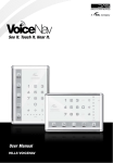
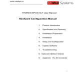
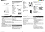
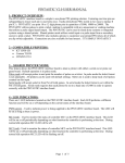
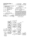
M~CROCOMPUTER
SYSTEMS CORPORATION
MSC-98OOH
WiNCHESTER DISC STORAGE SUBSYSTEM
USER'S MANUAL
JUNE 1981
PRELIMINARY
104221
6/30/81-0P47 -26
TABLE OF CONTENTS
SECTION
I
2
TITLE
GENERAL INFORMATION
1.1
Introduction
1.2
Description
INSTALLATION
2.1
Introduction
3
2.2
Unpacking and Inspection
3
2.3
Installation Procedures
3
2.3.1
Setting Line Voltage
3
2.3.2
Selecting Proper Fuse
5
2.3.3
Power Cord
8
2.4
3
6/30/SI-0P47-27
PAGE
Disc Drive Setup
9
2.4.1
Connecting to the HP-85
9
2.4.2
Select Code Switch
9
2.4.3
Device Address Switches
9
2.4.4
Installing Mass Storage ROM
12
OPERATING THE DISC DRIVE
3.1
Introduction
14
3.2
Overview
14
3.3
Controls and Indicators
14
3.4
Power On
14
3.5
Usi ng the Disc Drive
16
3.5.1
Accessing the Disc Drive
16
3.5.2
Working With Files
17
3.5.2.1
Create Command
17
3.5.2.2
Cat Command
i7
3.5.2.3
Mass Storage Is Command
18
3.5.2.4
3.5.2.5
Rename Command
Copy Command
19
3.5.2.6
Purge Command
21
19
SECTION
4
TITLE
PAGE
SERVICE INFORMATION
4.1
How to Obtain Repair Service
21
4.2
General Shipping Instructions
21
4.3
Repair Policy
21
APPENDICES
A
ACCESSORIES
23
B
ENVIRONMENTAL SPECIFICATIONS
24
C
LIMITED 90-DAY WARRANTY
25
6/30/81-0P47-28
TABLES
TABLE
TITLE
2-1
FUSE SELECTION
2-2
DEVICE ADDRESS SWITCH
6/30/81-0P47-29
PAGE
8
II
SECTION I
GENERAL INFORMATION
1.1
INTRODUCTION
The MSC- 9800H Winchester Disc Storage System (Figure 1- I) provides mass
storage capabilities for the HP-85 Computer.
The disc drive connects
directly to the HP-85 and requires only the Mass Storage ROM.
The ROM
provides all the necessary interface control so that the disc drive and the
HP-85 can communicate.
This manual contains all the information that the
user needs in order to install and use the disc drive.
For a detailed
description of the Mass Storage ROM consult the following HP manual:
Mass Storage ROM Manual HP Number: 00085-90447
1.2
DESrnlPTION
The MSC- 9800H has a total formatted capacity of 4.6 megabytes, divided
into four sections.
The capacity of each section is the equivalent of the
capacity of an 8-inch, double-sided flexible diskette.
From the user's point
of view, the MSC-9800H operates as four separate flexible disc drives
controlled by one controller.
The controller addresses each of the four
sections of the disc drive as a separate flexible disc drive.
6/30/81-0P47
-1-
FIGURE I-I HP9800H
6/30/81-0P47
-2-
SECTION 2
INSTALL ATION
2.1
INTRODUCTION
This section contains the information that is necessary in order to prepare
the 9800H disc drive for operation.
2.2
UNPACKING AND INSPECTION
The disc drive was carefully inspected, both electrically and mechanically,
before the factory shipped it. Remove the drive from the shipping carton and
carefully inspect the unit for any physical damage that may have occurred
during shipment. If you find any damage, notify your dealer immediately and,
also, file a claim with the carrier involved.
Save the shipping container in
case the unit must be returned for service or shipped to a new location.
NOTE: THE MSC-9800H is a precision device.
It has been built to withstand normal handling.
Care must be taken not to drop it or bump it
hard.
Evidence of excessive shock wi II void
the warranty.
2.3
INSTALLA TION PROCEDLRES
The installation procedures consist of the following:. setting the proper line
voltage, setting the device address, and connecting the HP-IB cable.
2.3.1
Setting Line Voltage
The factory configures the MSC- 9800H to operate at a line
voltage of 120 volts a.c. at a frequency in the range of 47 to 63
Hertz.
If the current installation has another voltage, then the
line voltage setting of 9800H must be changed. The procedure to
change the line voltage follows.
7/7/8I-OP47
-3-
WARNING
Remove the a.c. power cord from
the service outlet.
A sliding,
clear-plastic cover above the a.c.
connector on the rear pane I serves
as a safety mechanism.
Even
though there is a safety mechanism
on the rear, it is safer to unplug
the line cord.
I.
Remove the a.c. power cord from the service outlet and from the rear of the
disc drive. See Figure 2-1.
2.
Slide the plastic cover at the side of the line plug connector down all the way
so that the cover is over the line plug connector.
3.
Look at the small wafer at the top of the a.c. line connector. The wafer
shows one of the following numbers: 100, 120, 200, or 240; this number is the
voltage for which the disc drive is configured.
4.
If the number on the wafer differs from the voltage available at the
installation, remove the wafer from its slot. See Figure 2-2.
5.
The wafer has the numbers 100, 120, 200 and 240 on both sides. Observe the
number that corresponds to the voltage at the current installation.
6.
Position the wafer so that the number that corresponds to the voltage at the
current installation is visible and right side up at the left side of the wafer.
7.Re-insert the wafer in its slot, making certain that the selected number on
the wafer is still visible from the inserted position.
I'KlTE
The disc drive is now configured to
operate at
the voltage at the
current installation. No frequency
conversion is necessary.
8.
Slide the plastic cover back over the wafer.
7/7/81-0P47
-4-
9.
Plug the a.c. power cord into the a.c. connector at the rear of the disc drive.
This completes the setting of the line voltage.
2.3.2
Selecting Proper Fuse
The factory ships the disc drive with the correct fuse for 120
volts. For operation at other I ine voltages, the u~er must install
the proper fuse. See Figure 2-3 for fuse replacement.
FIGURE 2-1 REAR PANEL OF MSC-9800t-t DISC DRIVE
7/7/81-0P47
-5-
FIGURE 2-2 VOLTAGE-SETTING WAFER
6/30/81-0P47
-6-
FIGURE 2-3 REMOVING FUSE
6/30/81-0P47
-7-
The fuse receptacle is on the rear panel of the disc drive.
Table 2-1 lists the voltage settings and the proper fuse ratings for
the voltage settings.
TABLE 2-1 FUSE SELECTION
LINE VOLTAGE SETTING
FUSE RATING (250V)
100 to 120 vac
2 amperes
220 to 240 vac
1 ampere
To install or replace the fuse, first disconnect the power cord
from the power outlet.
2.3.3
I.
Remove the fuse by pulling out the fuse lever.
2.
Push the proper fuse into the clips (see Figure 2-3).
Power Cord
The power cord that the factory supplies must match the plug
requirements of your areaLJf the .disc drive has the wrong power
cord, get in touch with your local dealer or sales representative.
WARNING
Use only the power cord specified
by
Microcomputer
your area.
replace
Systems
for
If it is necessary to
the
power
cord,
the
replacement must have the same
polarity
warn i ng
as
the
must
original.
be
This
observed;
otherwise, a safety hazard from
electrical shock can exist.
Also,
using the wrong cord can damage
the disk drive.
6/30/81-0P47
-8-
2.4
DISC DRIVE SETUP
After the power requirements have been taken care of, the disc drive is ready
for connection to the HP-85.
The following paragraphs describe the
necessary connections and settings.
2.4.1
Connecting to the HP-85
The user must use an HP-IB Interface Module, model HP 82937 A,
in order to connect the disc drive to the HP-85 computer.
Hewlett-Packard supplies the Interface Module.
The following
procedure shows how to connect the disc drive to the HP-85
computer.
I.
Turn off the power on both the disc drive and the HP-85
computer.
2.
Plug the HP-IB Interface Module into an I/O port at the rear
of the HP-85.
3.
Refer to Figure 2-4 and plug the connector of the HP-IB
Interface Module into the mating HP-IB connector at the
rear of the disc drive.
2.4.2
Select Code Switch
The Hewlett-Packard factory sets the select code of the HP-IB
Interface Module.
If you must change the setting of the select
code, consult the manual for the HP-IB Interface Module.
2.4.3
Device Address Switches
Each device that connects to the HP-85 through the HP-85
Interface Module has an address that identifies it. The Interface
Module can accept up to eight devices, each of which must have a
separate address.
On the disc drive, the device address is set
using the DEVICE ADDRESS switches on the rear panel of the
disc drive. Table 2-2 lists the settings of the DEVICE ADDRESS
switches.
6/30/81-0P47
-9-
FIGURE 2-4 CONNECTING HP-IB
6/30/81-0P47
-10-
NOTE
Only switches 6, 7 and 8 of the
device
address
are
used.
Switches I through 5 must be set
to the OPEN position at all times.
TABLE 2-2 DEVICE ADDRESS SWITCH
Value
SWITCH NUMBER
6
7
8
Open
Open
Open
0
Open
Open
Clsd
I
Open
Clsd
Open
2
Open
Clsd
Clsd
3
Clsd
Open
Open
Clsd
Open
Clsd
4
5
Clsd
Clsd
Open
6
Cisd
Clsd
Clsd
7
Before shipping the disc drive, the factory sets the device address
to 3. If you need to change the device address, turn off the power
to the drive by setting the power switch on the rear panel to OFF.
It is very important that you turn
off the power before changing the
address switches.
6/30/81-0P47 -11-
Set a switch section to OPEN by Jsing a pointed object to press
the lower portion of the rocker to OPEN. Set a switch section to
CLOSED by pressing the upper portion of the rocker to CLOSED.
In the table CLOSED is indicated by CLSD (see Figure 2-5).
2.4.4
Installing Mass Storage ROM
In order to use the 9800H disc drive with the HP-85 computer, the
l
HP-85 Mass Storage ROM must be installed in the HP-85
computer.
You must first install the ROM in the ROM Drawer.
Then you must install the ROM Drawer in one of the four I/O
ports of the HP-85 computer.
For instructions in installing the
ROM and the ROM Drawer, consult the HP 82936A Rom Drawer
Instruction
Sheet
Programming Guide.
and
the
HP-85
Owner's
Manual
and
The HP-85 Mass Storage ROM Manual
contains complete instructions for using the ROM with disc
drives.
6/30/81-0P47
-12-
FIGURE 2-5 SETTING DEVICE ADDRESS SWITCHES
6/30/81-0P47
-13-
SECTION 3
OPERATING THE DISC DRIVE
3.1
INlRODUCTION
This section discusses the operation of the MSC- 9800H Winchester Disc
Storage System, referred to as the disc drive. Before reaching this point, the
user should have installed the disc drive as described in Section 2.
3.2
OVERVIEW
The storage capacity' of the disc drive is 4.6 megabytes; the HP-85 computer
sees this capacity as four separate storage capacities of approximately 1.15
megabytes, the equivalent of an eight-inch, double-sided flexible disc. These
separate storage capacities are designated volumes in the same manner that
individual
flexible
disc
drives
are;
these
volumes
initially
have
the
factory-assigned labels of DO, 0 I , 02 and 03, and each has its own directory.
All volumes, however, have the same HP-IB (device) address.
3.3
CONlROLS AND II'DICATORS
The disc drive has two controls and one indicator that the user must be aware
of. The two controls, located on the rear panel, are the power switch and the
device-address switch.
Both of these controls are discussed in Section 2.
The indicator, the drive accessed light, is on the front panel; it lights
whenever a volume is accessed (see Figure 3-1).
3.4
POWERON
Before turning on the disc drive, make certain that all connections have been
made. Refer to Section 2, Installation if necessary. Locate the power switch
on the rear panel and set it to the ON position. The disc drive requires about
20 seconds after the application of power before it is ready for operation.
Turn the disc drive on before applying power to the HP-85.
7/7/81-0P47
-14-
FIGURE 3-1 DRIVE ACCESSED LIGHT
6/30/81-0P47
-15-
3.5
USING THE DISC DRIVE
The manual for the Mass Storage ROM contains all the information that the
user needs to operate the disc drive. In that manual, all references that are
made to individual flexible disc drives are applicable to an individual volume
on the MSC-9800H disc drive. The following paragraphs in this section give
exarnples of some of the ways you can use the disc drive.
NOTE
Some commands like COpy and
PACK can take several minutes to
complete.
during
the
Do not press RESET
execution' of
these
commands: data will be lost.
3.5.1
Accessing the Disc Drive
The user can access the disc drive in one of two ways: using the
mass storage unit specifier (msus) or the volume label for a
specific volume.
These specify the exact location on the disc
drive where information is to be either stored or retrieved from.
The form of the msus is as follows:
":0 interface-select-code device-address drive-unit-number"
The four volumes on the disc drive leave the factory initialized as
volumes "DO", "0 I", "02" and "03".
When using volume labels to specify a volume, the HP-85 must
search for a match.
The search begins with the low HP-IB
addresses and checks each unit on attached drives. Therefore, if
2 or more MSC-9800 disc subsystems are attached on the same
HP-IB interface, the one with the higher device address cannot be
accessed with the factory supplied volume labels since the HP-85
7/7/81-0P47
-16-
will find those labels on the subsystem with the lower device
address and stop searching.
Therefore, to initially access the
volumes at higher device adddresses, the :msus form must be
used.
By using the VOLUME IS command, the volume labels can be
changed to unique names on anyone or all of the MSC-9800H
subsystems attached. Then the volume label form can be used to
specify a volume.
Working With Files
3.5.2
Throughout the following discussion, the volume labels remain the
same unless specifically changed.
Be careful
to note
the
difference between 0 (zero) and 0 (the letter).
The following are only examples of using the four volumes. For a
complete description of using the commands, refer to the Mass
Storage ROM manual.
3.5.2.1
CREATE Command
One type of fi Ie is the data fi Ie which you must first
create by using the CREATE command.
Type the
following:
CREATE "FILE.O I", 10, 50
You hdve now created a fi Ie named "FILE.O I" with a
logical length of I 0 records, each record having 50
bytes. This file exists only on volume (unit) 01.
\
3.5.2.2
CAT Command
To make certain that the tile "FILE.O I" does exist,
type the following:
"CAT ".0 I"
717181-0P47
-17-
The resulting list on your CRT indicates that the file
does exist.
To make certain that it exists only on
volume ".DI" and not on volumes ".DO", ".D2", or
".D3", enter the following commands, one after
another, noticing the indication on your CRT after
each entry:
CAT ".DO"
CAT ".D2"
CAT ".D3"
The file "FILE.D I" does not appear on the CRT after
any of the commands are executed.
3.5.2.3
MASS STORAGE IS Command
If the disc subsystem is installed and powered on when
the HP-85 is powered on, the HP-85 automatically
assigns unit 0 of the disc with the lowest HP-IB
address as the default mass storage device. (Without a
disc attached, the HP-85 tape is the default mass
storage device.)
Type
MASS STORAGE IS ".0 I"
It is no longer necessary to specify a volume as part of
the file specifier when working with unit I (volume
".0 I").
Type
CAT
The CRT displays the directory for ".01".
"FILE" is shown.
6/30/81-0P47
-18-
The file
At any time the identify of the
default mass storage unit can be displayed by typing
CAT.
3.5.2.4
RENAME Command
A file can be renamed without changing the contents
of the file. Type the following:
''RENAME "FILE" TO "BOOK"
Now type:
CAT
The name of the file "FILE" is now "BOOK".
3.5.2.5
COpy COITImand
It is always a good idea to make certain that you have
a copy of your valuable information.
The copy
command enables you to copy infromation from a file
on one volume to another volume,,- The name of the
file can remain the same.
For example, type the
following:
COPY "BOOK.D I" TO "BOOK.DO"
The information in file "BOOK.D I" is copied into
"BOO K .00" .
The name of the new file need not remain the same.
Type the following:
COPY "BOOK.D I" to "NEW. DO"
File "NEW.DO" contains the same information as file
"BOOK.D I"; only the names are different.
Use the
CA T command to verify that the files are now on
"DO" •
6/30/81-0P47
-19-
).j.2.o
PURGE Command
Files can be removed from any of the directories of
the disc drive.
The purge command permits this.
Type the following:
PURGE "BOOK.D I"
Now type:
Cat ".01"
The directory of volume ".0 I" no longer lists file
"BOOK.D I".
The command PURGE "BOOK.DO",O
purges "BOOK" and all files after it on volume ".00".
6/30/81-0P47
-20-
SECTION 4
SERVICE INFORMATION
4.1
HOW TO OBTAIN REPAIR SERVICE
F or information on obtaining service in your area, contact your dealer or
Microcomputer Systems Corporation.
Standard bench service is provided for under your warranty. It calls for the return
of the unit(s), shipping prepaid, to Microcomputer Systems Corporation or a repair
facility where the repair is done on a fixed charge basis (depending on the assembly
containing that malfunction) if the unit is out of warranty, or free of charge, if the
unit is in warranty.
4.2
GENERAL SHIPPING INSTRUCTIONS
Should you ever need to ship a unit, be sure it is packed in a protective package.
We recommend that you save the original shipping-container for this purpose.
In-transit damage is not covered by the warranty.
Microcomputer Systems
Corporation also suggests that the customer always insure shipments.
4.3
REPAIR POLICY
For bench service at MSC repair facilities, the 9800H will normally be repaired and
reshipped within seven (7~ working days of receipt of the unit at that facility. Plan
additional time for in-transit. This is an average time and may vary depending on
workload.
Whether the unit is under warranty or not, it is your responsibil ity to
pay shipping charges for delivery to the repair facility.
If the unit is under
warranty, Microcomputer Systems Corporation will pay the shipping charges for
delivery back to the customer.
If your MSC-9800H subsystem malfunctions, you can help assure efficient servicing
by following these guidelines:
I.
Make certain that all connections have been properly made.
6/30/81-0P47
-21-
2.
Check to see that the MSC- 9800H power cord is connected, the power switch
is on, and the fuse is inserted and not blown.
3.
If using :msus volume specifiers, check that you are using the device address
which was set on the MSC-9800H the last time it was powered on.
4.
Be sure that device address switches I through 5 are pressed in at the
bottom.
5.
Recheck to s~e if the commands have been entered and used correctly.
6.
If after following the maintenance procedures, you determine that repair is
required, you will need to have the following items with your unit(s) at the
time of service.
a.
A description of the configuration of the HP-8s exactly as it was at the
time of malfunction, e.g., any plug- in modules, tape cartridges, or
other
accessories
that
were
in use with
the
9800-H
when
the
malfunction occurred.
b.
A brief description of the malfunction symptoms for service personnel.
c.
Printouts or any other materials that illustrate the problem area.
d.
A copy of the sales slip or other proof of purchase to establish your
warranty coverage period.
6/30/81-0P47
-22-
APPENDIX A
ACCESSORIES
A.I
INTRODUCTION
Each drive is shipped with the following accessories.
If upon unpacking the
disc drive you find that an item is missing, get in touch with your dealer.
Power Cord
User's Manual
Fuse
6/30/81-0P47
-23-
APPENDIX B
ENVIRONMENTAL SPECIFICATIONS
Operating
Non-O~erating
Temp °c
10 to 40°C
-10 to 55°C
Temp of
SO to 104°F
+ 14 to 131°F
Humidity
8-80%
Altitude
10,000'
6/30/81-0P47
-24-
25,000'
APPENDIX C
MSC-98OOH
LIMITED 9O-DAY WARRANTY
WHAT IS COVERED
The MSC- 9800H is warranted by Microcomputer Systems Corporation against
defects in materials and workmanship for 90 days from date of original purchase.
If you sell your MSC-9800H or otherwise transfer its ownership, the wdrranty is
automatically transferred to the new owner and remains in effect for the original
90-day period. During the warranty period, we will repair or at our option, replace
at no charge an MSC-9800H that proves to be defective, provided it is returned,
shipping prepaid, to Microcomputer Systems Corporation, 432 Lakeside Drive,
Sunnyvale, California, 94086, or an authorized MSC repair facility.
You are
responsible for all customs duties in connection with the return of the MSC-9800H.
WHAT IS NOT COVERED
This warranty does not apply if the product has been damaged by accident or
misuse, or as a result of service or modification by other than an authorized MSC
repair facility or by hardware, software, interfacing or peripherals not provided by
MSC.
MSC shall have no obligation to modify or update products once
manufactured.
No other express warranty is given. The repair or replacement of a product is your
exclusive remedy.
ANY IMPLIED WARRANTY OF MERCHANTIBILITY OR
FITNESS IS LIMITED TO THE 90-DAY DURATION OF THIS WRITTEN
WARRANTY. Some states or provinces do not allow limitations on how long an
implied warranty lasts so the above limitation or exclusion may not apply to you.
IN NO EVENT SHALL MICROCOMPUTER SYSTEMS CORPORATION BE LIABLE
FOR CONSEQUENTIAL DAMAGES. Some states or provinces do not allow the
exclusion or limitation of incidental or consequential damages, so the above
limitation or exclusion may not apply to you.
This warranty gives you specified legal rights, and you may also have other rights
which vary from state to state or province to province.
THIS IS YOUR WARRANTY. PLEASE RETAIN FOR YOUR RECORDS.
6/30/81-0P47
-25-