1
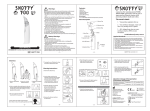
Daking Audio Mic Pre 500 Manual VERSION 1.0 Hendrik David Gideonse XIX 5/16/2011 Safety Considerations 1. Read, follow and keep these instructions. 2. Heed all warnings. 3. Do not use this equipment in or near water. Do not place liquids on or near the device because the device might be damaged during a spill. 4. Clean only with a soft dry cloth. 5. Do not block any ventilation openings. Install in accordance with the manufacturer’s instructions. 6. Do not install near any heat sources such as radiators, heat registers, stoves, or other apparatus (including amplifiers) that produce heat. 7. Do not defeat the safety purpose of the polarized or grounding-type plug. A polarized plug has two blades with one wider than the other. A grounding-type plug has two blades and a third grounding prong. The wide blade or the third prong are provided for your safety. If the provided plug does not fit into your outlet, consult an electrician for replacement of the obsolete outlet. 8. Protect the power cord and all connecting cables from being walked on or pinched particularly at plugs, receptacles, and the point where they exit from the device. 9. Only use attachments/accessories specified by the manufacturer. 10. Unplug this device when unused for long periods of time. 11. Refer all servicing to qualified service personnel. Servicing is required when the apparatus has been damaged in any way, such as when a power-supply cord or plug is damaged, liquid has been spilled or objects have fallen into the apparatus, the apparatus has been exposed to rain or moisture, does not operate normally, or has been dropped. 12. Do not overload wall outlets and extension cords as this can result in a risk of fire or electric shock. 2 Contents 1 Daking Audio Mic Pre 500 ......................................................................................... 4 1.1 About Daking Audio ............................................................................................ 4 1.2 Quick Start Guide ................................................................................................. 4 1.2.1 Don’t read the manual! ................................................................................. 4 1.2.2 Installation of 500 Series Units ..................................................................... 5 1.2.3 Power Up Procedure ..................................................................................... 5 1.2.4 Power Supply Fault ....................................................................................... 5 1.2.5 Basic Set Up .................................................................................................. 5 1.2.6 Instrument Input (¼”) ................................................................................... 6 1.3 Front Panel ........................................................................................................... 7 1.3.1 LED VU and Peak Meter .............................................................................. 7 1.3.2 The HPF (High Pass Filter) Knob................................................................. 8 1.3.3 The Gain Knob.............................................................................................. 9 1.3.4 ¼” Instrument Input Jack .............................................................................. 9 1.3.5 ¼” Button ...................................................................................................... 9 1.3.6 Pad Button................................................................................................... 10 1.3.7 +48 Phantom Button ................................................................................... 10 1.3.8 Ø Phase Button ........................................................................................... 10 1.4 Specifications ..................................................................................................... 11 3 1 Daking Audio Mic Pre 500 1.1 About Daking Audio Congratulations! You’ve purchased a Mic Pre 500, a very high end piece of gear! The Mic Pre 500 uses all discrete transistor Class A circuits, THAT Corporation differential amp and printed circuit board mounted switches. Signal capacitors are precision polypropylene or ultra low-leakage electrolytic types. Our boards are assembled on a mil-spec assembly line. The chassis are stainless steel for maximum RF and hum rejection and a long lasting finish. Every unit is hand finished, tested, burned in, and tested again in a second facility. Also, we just couldn’t stand to use plastic knobs, so we designed our own anodized, engraved aluminum knobs that give a much more precise and quality feel. We designed our gear to be gear you’d own for life, not some passing fancy you’d leave in the dust once you figured what the good stuff sounds like. This IS the good stuff. -Geoff Daking 1.2 Quick Start Guide 1.2.1 Don’t read the manual! Most of you will already know how to use mic preamps perfectly well and might be even a little offended at the idea of reading the instruction manual. So don’t read it. This manual is not for you. This manual is for someone that knows enough to buy the very best (Daking of course!), but doesn’t have a lot of experience using recording gear. You might be a bass player who just got a DAW and wants a cleaner more accurate sound from your mics in your home studio. You might be a student that just got a check from Mom & Dad and who wants to go buy something nice for yourself. You might be the guy standing ankle-deep in a pool of salt water, trying to yank the grounding pin off your mixer’s power cord so you can plug it into your 2-prong ungrounded outdoor outlet. This manual is especially for you! Whenever you see the Duh! Guy, you can be assured that most professionals will already know this stuff. Be sure to explain this stuff to your friends in a snotty and condescending tone, so you too can be part of the tradition of know-it-all engineers and recordists! 4 1.2.2 Installation of 500 Series Units Follow the instructions provided by the manufacturer of your 500 series rack and power supply to install your Mic Pre 500. Make sure the card is firmly seated in the slot and fully screw the installation screws into the 500 series rack enclosure. Your input and output connections will be provided on the rear of the rack enclosure either as XLR connectors or part of a DSUB 25 array. 1.2.3 Power Up Procedure When you first power up your 500 series rack enclosure the Mic Pre 500 goes into a test cycle while the Class A amplifier warms up. First all 8 LEDs for the meter will illuminate for a fraction of a second and up to a couple of seconds. This is the processor for the level meter booting up and beginning to run the metering program. Next four LEDs will light at a time, with every other LED flashing back and forth for about three seconds. Next it will start to show audio levels if audio is present. 1.2.4 Power Supply Fault There are many 500 series racks available, each with slightly different power supplies. Some older 500 racks are notorious for power supply problems. 500 series power supplies are actually two supplies, a +16 Volt and a -16 Volt source. If you turn on the unit, but get no audio, there is a chance that one of the supplies in the rack has either gone down or is in protection mode. This has the potential to cause damage to your Mic Pre 500 if left like this for a long time. To verify that a power supply fault has occurred, engage all of the push buttons including the 1/4" input switch with the blue LED. If the blue LED does NOT light, then there is a problem with your power supply. 1.2.5 Basic Set Up The job of a microphone amplifier is to make a mic level signal into a line level signal so that it can be recorded, mixed or processed. Plug a microphone into the Input Jack for the Mic Pre 500 on the rear of the 500 series enclosure using a microphone (XLR Female to XLR Male) cable. If the mic you are using is a condenser microphone that requires phantom power, push in the +48 Button to engage phantom power. Patch out of the Output Jack of the same preamp to the line level input of your recording device using the appropriate cable. 5 1.2.6 Instrument Input (¼”) The instrument input accepts an instrument level signal like that from a guitar, bass or keyboard. Plugging a speaker level signal into your Mic Pre 500 may blow it up. This signal is far too hot to work properly with your preamp. 6 1.3 Front Panel 1.3.1 LED VU and Peak Meter The VU Meter for the Mic Pre 500 is a true VU Meter with 300ms averaging ballistics. The main difference between this meter and a mechanical VU meter is that this meter extends to +22dB, while a mechanical meter only goes up to +3dB. This feature allows the engineer to see level with much greater accuracy and detail above +3dB. The VU Meter on the Mic Pre 500 also has a wonderful feature of a floating peak indicator which shows the peak level with a single LED light and the average level with a series of LEDs. 7 The highest point on the meter is labeled with “PK” which is the peak indicator. When this LED is lit, the signal has reached or exceeded 23dBu. Most audio interfaces will clip at +18dBu, while most professional mixing consoles will clip between +24dBu to +30dBu. VU Meters measure the RMS (Root Mean Square) of an audio signal. Often the RMS is considered to the “continuous” level of the signal. A PPM (Peal Program Meter) measures the signal much more quickly and keeps track of the absolute value of the greatest voltage in the audio signal. This is why the Peak Indicator (PK) can be lit when the VU meter is showing a much lower signal. The peaks of an audio signal are much higher than the RMS of the audio signal. NOTE: While most VU meters are calibrated to 0dB VU = +4dBu, this meter is in fact a true dBu meter where 0dB on the meter is in fact 0dBu. This means that when the Mic Pre 500’s VU meter is reading 0dB and you patch into another standard VU meter directly from the mic pre, you will show a reading of -4dB. 1.3.2 The HPF (High Pass Filter) Knob Why do we need it? In the olden-timey days (or even now if you can afford it!) we recorded audio on magnetic tape which isn’t good at reproducing very low frequencies. Tracking at 30 IPS (Inches Per Second), frequencies below 40 Hz were severely attenuated and even at 15 IPS, frequencies below 20 Hz were attenuated. Digital equipment happily records frequencies ranging from 40 Hz all the way down to DC. There are a number of problems with tracking these low and unwanted frequencies. In a major studio that has been acoustically isolated and has wonderful full-range monitors, these very low frequencies don’t often make it into microphones and if they do you can hear them with the monitors that are capable of producing the bottom octave (20Hz – 40 Hz). In home studios that don’t have a perfect monitoring solution, the engineer can’t hear that this low rumble is on the tracks. Low frequency problems can come from traffic or subway noise hundreds of feet away. A concrete or wood-joisted floor is essentially an enormous drum head and every footstep creates low frequency energy which can easily travel into microphones. The other problem with recording unwanted low frequency sounds is wasting the available bandwidth on non-artistically essential frequencies. If you are recording a female vocal, for instance, you can be pretty sure that any frequencies below 80 Hz are not part of the vocal performance. There might be plosives from popped P’s and rumble from the A Train and the HVAC system. That rumble will not only make your bass muddy sounding in the mix, but it will diminish the intensity of low frequency 8 transients. How to use it: After you have set your gain level appropriately, start to turn the HPF knob clockwise until you can hear the low frequencies start to thin out in the audio. Now back the knob off counter-clockwise until you can’t hear the HPF. Now you have removed the unwanted and unnecessary frequencies, but the filter isn’t affecting the timbre of the audible frequencies of your source material. 1.3.3 The Gain Knob The Gain Knob allows you to control the amount of gain added to the input signal. The knob is continuously variable allowing a high level of control over level. The gain should be set as high as possible without either seeing the peak indicator (*) flash on the VU meter, hearing audible clipping or distortion, or overloading the following stage in the signal chain. For instance, your Mic Pre 500 can support outputs up to +22dB, but most audio interfaces clip at +18dB. The gain control would have to be set so as to not overload the audio interface. Professional consoles are capable of handling levels as high as +30dB in some cases. One common procedure for setting gain is to set the level while the channel is muted. Turn up with gain until the peak indicator (*) flashes during the loudest parts of the performance. Then reduce the gain by a few dB. Then disengage the mute of the console or DAW and listen to the signal. Note that many performers will be significantly louder and more energetic when they believe they are recording compared to when they believe that levels are being set. If you are still showing peaking on the VU meter, but the gain switch is turned down all the way, engage the Pad button to reduce gain by 20dB. This will not affect the timbre of the audio, just the level. 1.3.4 ¼” Instrument Input Jack The ¼” Instrument Input Jack is specifically designed to allow users to plug a guitar, bass or keyboard into the front of the preamp. The signal from this jack does not pass though the input transformer, but rather is unbalanced. You must engage the ¼” Button in order to use the front ¼” jack. 1.3.5 ¼” Button This button switches the input of the mic pre to the front ¼” input and disengages the rear mic input. 9 1.3.6 Pad Button The Pad button is a 20dB attenuator useful when the gain switch is in its lowest position and the peak indicator (PK) is still being lit. Most commonly the Pad button will be required for extremely dynamic sources like drums and percussion, or extremely loud sources like electric guitar through a large amplifier. The Pad button only works on the microphone input, not on the instrument input. 1.3.7 +48 Phantom Button This button controls the 48 volt phantom power which is used to power the onboard electronics in condenser microphones or active direct injection (DI) boxes. 1.3.8 Ø Phase Button The Ø button flips the phase of the audio signal by swapping pin 2 and pin 3 of the XLR jack of the microphone input. This does not affect the phase of the instrument input because it is unbalanced. Most often this is used when two microphones are being used on the same source, like the top and bottom microphones for a snare drum. Often the phase is flipped on the bottom microphone so that the two microphone signals will be in phase. When two microphones are out of phase and mixed together the sound often is hollow sounding, with some frequencies boosted and some frequencies cut. Phase flip is also commonly used when two microphones are used on a single guitar speaker cabinet. 10 1.4 Specifications Transformer balanced input THAT Corporation differential amp output Discrete transistor circuitry Class "A" amplifiers for the preamp and High Pass Filter Single sided amplification Continuously Variable Gain Control 20 Segment vu Meter (-20 to +25) +23dB Peak indicator Floating Peak indicator All relay switching w/gold bi-furcated contacts Switched +48 Volt Phantom power 20dB pad on mic input All metal construction for noise immunity Aluminum knobs Power supply included 70dB gain Specifications are subject to change without notice. 11