1
Migration Guide
SLC/MicroLogix 1500 to CompactLogix Migration Guide
Important User Information
Solid-state equipment has operational characteristics differing from those of electromechanical equipment. Safety
Guidelines for the Application, Installation and Maintenance of Solid State Controls (publication SGI-1.1 available from
your local Rockwell Automation® sales office or online at http://www.rockwellautomation.com/literature/) describes some
important differences between solid-state equipment and hard-wired electromechanical devices. Because of this difference,
and also because of the wide variety of uses for solid-state equipment, all persons responsible for applying this equipment
must satisfy themselves that each intended application of this equipment is acceptable.
In no event will Rockwell Automation, Inc. be responsible or liable for indirect or consequential damages resulting from the
use or application of this equipment.
The examples and diagrams in this manual are included solely for illustrative purposes. Because of the many variables and
requirements associated with any particular installation, Rockwell Automation, Inc. cannot assume responsibility or
liability for actual use based on the examples and diagrams.
No patent liability is assumed by Rockwell Automation, Inc. with respect to use of information, circuits, equipment, or
software described in this manual.
Reproduction of the contents of this manual, in whole or in part, without written permission of Rockwell Automation,
Inc., is prohibited.
Throughout this manual, when necessary, we use notes to make you aware of safety considerations.
WARNING: Identifies information about practices or circumstances that can cause an explosion in a hazardous environment,
which may lead to personal injury or death, property damage, or economic loss.
ATTENTION: Identifies information about practices or circumstances that can lead to personal injury or death, property
damage, or economic loss. Attentions help you identify a hazard, avoid a hazard, and recognize the consequence.
SHOCK HAZARD: Labels may be on or inside the equipment, for example, a drive or motor, to alert people that dangerous
voltage may be present.
BURN HAZARD: Labels may be on or inside the equipment, for example, a drive or motor, to alert people that surfaces may
reach dangerous temperatures.
IMPORTANT
Identifies information that is critical for successful application and understanding of the product.
Allen-Bradley, Rockwell Software, Rockwell Automation, CompactLogix, ControlLogix, MicroLogix, Studio 5000, RSLogix, POINT I/O, FLEX, and TechConnect are trademarks of Rockwell Automation, Inc.
Trademarks not belonging to Rockwell Automation are property of their respective companies.
Table of Contents
Important User Information . . . . . . . . . . . . . . . . . . . . . . . . . . . . . . . . . . . . . . . . 2
Table of Contents
Preface
About This Publication. . . . . . . . . . . . . . . . . . . . . . . . . . . . . . . . . . . . . . . . . . . . . 5
Studio 5000 Environment . . . . . . . . . . . . . . . . . . . . . . . . . . . . . . . . . . . . . . . . . . 5
Additional Resources . . . . . . . . . . . . . . . . . . . . . . . . . . . . . . . . . . . . . . . . . . . . . . . 6
Chapter 1
Overview
Why Convert . . . . . . . . . . . . . . . . . . . . . . . . . . . . . . . . . . . . . . . . . . . . . . . . . . . . . . 7
What Is Needed. . . . . . . . . . . . . . . . . . . . . . . . . . . . . . . . . . . . . . . . . . . . . . . . . . . . 7
SLC EtherNet/IP Adapter. . . . . . . . . . . . . . . . . . . . . . . . . . . . . . . . . . . . . . . . . . 8
1747-AENTR Connections . . . . . . . . . . . . . . . . . . . . . . . . . . . . . . . . . . . . . 9
1747-AENTR and Rack Optimization . . . . . . . . . . . . . . . . . . . . . . . . . . . 9
Exclusive Owner, Input Only, Listen Only, and None Connection
Types. . . . . . . . . . . . . . . . . . . . . . . . . . . . . . . . . . . . . . . . . . . . . . . . . . . . . . . . . . 9
Add I/O Modules Online . . . . . . . . . . . . . . . . . . . . . . . . . . . . . . . . . . . . . 10
Using the 1747-AENTR Module in a Redundant Logix System . . 10
SLC to Logix Memory Comparison . . . . . . . . . . . . . . . . . . . . . . . . . . . . . . . 11
Scan Time Comparison. . . . . . . . . . . . . . . . . . . . . . . . . . . . . . . . . . . . . . . . . . . 11
Local Rack SLC 500 I/O Modules . . . . . . . . . . . . . . . . . . . . . . . . . . . . . 11
Remote Rack SLC 500 I/O Modules. . . . . . . . . . . . . . . . . . . . . . . . . . . 12
Overall Performance Expectations . . . . . . . . . . . . . . . . . . . . . . . . . . . . . 12
Logix Controller Boot Time. . . . . . . . . . . . . . . . . . . . . . . . . . . . . . . . . . . 13
Synchronous Versus Asynchronous I/O Scans . . . . . . . . . . . . . . . . . . 13
SLC I/O Local and Remote Rack Size . . . . . . . . . . . . . . . . . . . . . . . . . . . . . 14
Keeping I/O . . . . . . . . . . . . . . . . . . . . . . . . . . . . . . . . . . . . . . . . . . . . . . . . . . . . . 14
Chapter 2
Migration Considerations
Document Current System Layout . . . . . . . . . . . . . . . . . . . . . . . . . . . . . . . .
PLC-5/SLC Interactive Migration Planner . . . . . . . . . . . . . . . . . . . . .
Define Future Requirements . . . . . . . . . . . . . . . . . . . . . . . . . . . . . . . . . . . . . .
Device-level Ring Topologies . . . . . . . . . . . . . . . . . . . . . . . . . . . . . . . . . .
Using DeviceNet Network . . . . . . . . . . . . . . . . . . . . . . . . . . . . . . . . . . . .
Use of Advanced Modules. . . . . . . . . . . . . . . . . . . . . . . . . . . . . . . . . . . . .
Communication With an SLC Controller Over DH485, DH+,
Ethernet, or Serial Networks . . . . . . . . . . . . . . . . . . . . . . . . . . . . . . . . . .
1747-AENTR Backplane Power Considerations. . . . . . . . . . . . . . . . . . . .
Using Integrated Architecture Builder to Plan Hardware Migration . .
Replace Only the Local SLC Controller . . . . . . . . . . . . . . . . . . . . . . . .
Replace the Local SLC System with CompactLogix System . . . . . .
Adding a Chassis . . . . . . . . . . . . . . . . . . . . . . . . . . . . . . . . . . . . . . . . . . . . .
Network Connection Options for the Remote (SLC System) I/O
Chassis . . . . . . . . . . . . . . . . . . . . . . . . . . . . . . . . . . . . . . . . . . . . . . . . . . . . . .
Create Project Bill of Material . . . . . . . . . . . . . . . . . . . . . . . . . . . . . . . . .
Rockwell Automation Publication 1769-AP001B-EN-P - May 2015
15
15
17
17
17
18
18
19
20
20
26
33
36
41
3
Table of Contents
Chapter 3
Conversion
Introduction . . . . . . . . . . . . . . . . . . . . . . . . . . . . . . . . . . . . . . . . . . . . . . . . . . . . . 43
Download the standalone RSLogix Project Migrator. . . . . . . . . . . . . 43
What to Expect from the RSLogix Project Migrator . . . . . . . . . . . . . 45
Application Code Conversion . . . . . . . . . . . . . . . . . . . . . . . . . . . . . . . . . . . . . 45
Translate an RSLogix 500 Program to a Logix Designer Program . . . . . 50
Resolve the Differences in the New Logix Program . . . . . . . . . . . . . . . . . . 57
SLC Controllers Data Tables and Logix Controller Tags. . . . . . . . . 57
Resolve Program Code Issues . . . . . . . . . . . . . . . . . . . . . . . . . . . . . . . . . . 57
Locating PCE Instructions . . . . . . . . . . . . . . . . . . . . . . . . . . . . . . . . . . . . 58
Recognizing the Instructions . . . . . . . . . . . . . . . . . . . . . . . . . . . . . . . . . . 59
Resolving PCE Instructions . . . . . . . . . . . . . . . . . . . . . . . . . . . . . . . . . . . 59
Common PCE Issues . . . . . . . . . . . . . . . . . . . . . . . . . . . . . . . . . . . . . . . . . . . . . 59
Map PLC/SLC Messages . . . . . . . . . . . . . . . . . . . . . . . . . . . . . . . . . . . . . . . . . 61
Resolving Issues with Physical I/O . . . . . . . . . . . . . . . . . . . . . . . . . . . . . . . . . 62
MOV Example . . . . . . . . . . . . . . . . . . . . . . . . . . . . . . . . . . . . . . . . . . . . . . . 62
CPS Example. . . . . . . . . . . . . . . . . . . . . . . . . . . . . . . . . . . . . . . . . . . . . . . . . 63
Alias Example . . . . . . . . . . . . . . . . . . . . . . . . . . . . . . . . . . . . . . . . . . . . . . . . 65
Replace SLC Processor and Adapters. . . . . . . . . . . . . . . . . . . . . . . . . . . . . . . 66
Set the Network Address Switches . . . . . . . . . . . . . . . . . . . . . . . . . . . . . 66
Determine Power Requirements . . . . . . . . . . . . . . . . . . . . . . . . . . . . . . . 67
Install the Adapter Module in the Chassis . . . . . . . . . . . . . . . . . . . . . . 67
Connect Your Adapter to the Ethernet/IP Network through RJ45
Connection . . . . . . . . . . . . . . . . . . . . . . . . . . . . . . . . . . . . . . . . . . . . . . . . . . 69
Replace Other Components. . . . . . . . . . . . . . . . . . . . . . . . . . . . . . . . . . . . . . . 70
Appendix A
Program Conversion Errors (PCE)
Messages
Introduction . . . . . . . . . . . . . . . . . . . . . . . . . . . . . . . . . . . . . . . . . . . . . . . . . . . . . 73
Appendix B
I/O Modules
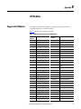
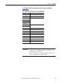
Supported I/O Modules . . . . . . . . . . . . . . . . . . . . . . . . . . . . . . . . . . . . . . . . . . 75
Unsupported I/O Modules. . . . . . . . . . . . . . . . . . . . . . . . . . . . . . . . . . . . . . . . 76
Appendix C
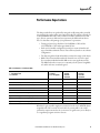
Performance Expectations
. . . . . . . . . . . . . . . . . . . . . . . . . . . . . . . . . . . . . . . . . . . . . . . . . . . . . . . . . . . . . . . . . 79
Appendix D
Advanced Modules
Use Advanced Modules in a Logix System . . . . . . . . . . . . . . . . . . . . . . . . . . 81
Appendix E
Migrating MicroLogix 1500
controllers to CompactLogix
Index
4
RSLogix Project Migrator tool. . . . . . . . . . . . . . . . . . . . . . . . . . . . . . . . . . . . . 83
Rockwell Automation Publication 1769-AP001B-EN-P - May 2015
Preface
About This Publication
This document focuses on converting an SLC program to a Logix program and
migrating the existing SLC I/O to an Ethernet network thereby helping to
leverage the existing I/O and minimize cost and risk. This document can be used
in the planning stages to help identify issues so that you can anticipate the work
involved in the conversion. The ideas presented in this document require
Studio 5000 Logix Designer software version 21 or later and RSLinx™ software
version 2.59 or later.
This document focuses on converting an existing SLC program to a
CompactLogix™ controller. If you want to convert your SLC program to a
1756 Logix controller the process is similar to what is presented in this manual.
The logic converter tool used for SLC also supports conversion of MicroLogix
program to CompactLogix. Refer to Appendix E in this document for a brief
guidance on converting MicroLogix 1500 program to CompactLogix.
Studio 5000 Environment
The Studio 5000™ Engineering and Design Environment combines engineering
and design elements into a common environment. The first element in the Studio
5000 environment is the Logix Designer application. The Logix Designer
application is the rebranding of RSLogix 5000 software and will continue to be
the product to program Logix5000™ controllers for discrete, process, batch,
motion, safety, and drive-based solutions.
The Studio 5000 environment was introduced in version 21.
The Studio 5000 environment is the foundation for the future of Rockwell
Automation engineering design tools and capabilities. The Studio 5000
environment is the one place for design engineers to develop all of the elements of
their control system.
Rockwell Automation Publication 1769-AP001B-EN-P - May 2015
5
Preface
Additional Resources
These documents contain additional information concerning related products
from Rockwell Automation.
Resource
Description
SLC EtherNet Adapter User Manual, publication 1747-UM076 Reference guide for the EtherNet/IP Adapter Module.
SLC EtherNet Adapter Installation Instructions, publication
1747-IN521
Installation instructions for the EtherNet/IP Adapter
Module.
Converting PLC-5 or SLC 500 Logic to Logix5550 Logic
Reference Manual, publication 1756-RM085
Information on converting a PLC-5 or SLC 500 Logic to
Logix5550.
CompactLogix 5370 Controllers User Manual, publication
1769-UM021
Describes how to install, use, and troubleshoot
CompactLogix controllers.
CompactLogix Controllers Specifications Technical Data,
publication 1769-TD005
Provides CompactLogix controllers specifications.
Industrial Automation Wiring and Grounding Guidelines,
publication 1770-4.1
Provides general guidelines for installing a Rockwell
Automation industrial system.
Product Certifications website, http://www.ab.com
Provides declarations of conformity, certificates, and
other certification details.
You can view or download publications at
http:/www.rockwellautomation.com/literature/. To order paper copies of
technical documentation, contact your local Allen-Bradley distributor or
Rockwell Automation sales representative.
6
Rockwell Automation Publication 1769-AP001B-EN-P - May 2015
Chapter
1
Overview
Why Convert
Migration solutions help you to achieve increased productivity and lessen your
risk of maintaining your legacy equipment. Work with a supplier that has the
product, service, and industry knowledge to partner with you on an upgrade
strategy that will help you maximize your competitive advantage. Rockwell
Automation works with you to outline a plan to accomplish the following:
• Lower conversion time and labor costs
• Reduce risk by preserving existing field wiring connections
• Lower engineering costs
• Minimize production downtime
What Is Needed
You need the following items for your migration project:
• Current SLC 500 or MicroLogix 1500 control system
– RSLogix 500 version 8.0 or later
• CompactLogix Controller
– Studio 5000 Logix Designer software version 21, or later, with
RS Logix Project Migrator Tool version 3.0 or later
– Integrated Architecture Builder version 9.6.0.4 or later
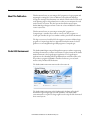
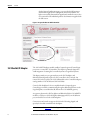
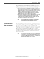
1. Go to http://www.rockwellautomation.com.
2. Click the Support tab, under Selection, Design, and Configuration Tools.
3. Click System Configuration.
Figure 1 - System Configuration
Rockwell Automation Publication 1769-AP001B-EN-P - May 2015
7
Chapter 1
Overview
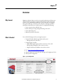
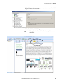
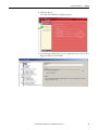
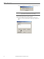
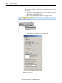
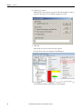
On the System Configuration page, you can order the full version or
download the light version of Integrated Architecture Builder. The
light version is fully functional but significantly smaller because it does
not contain all of the individual product documentation supplied with
the full version.
Figure 2 - Integrated Architecture Builder Download
SLC EtherNet/IP Adapter
The 1747-AENTR adapter module enables CompactLogix and ControlLogix
processors to control SLC I/O modules. The adapter is primarily designed to
enable migration of existing SLC controlled systems to Logix-based systems.
The adapter mainly acts as a gateway between the SLC backplane and
EtherNet/IP and typically replaces an SLC controller in the 1746 rack. On
remote SLC racks, it replaces the 1747-ASB module or the ControlNet adapters,
catalog numbers 1747-ACN15 and 1747-ACNR15.
Control of the backplane I/O is accomplished with a CompactLogix or
ControlLogix controller communicating through an EtherNet/IP router in the
Logix backplane, across EtherNet/IP, and into the 1747-AENTR gateway.
As a gateway between the SLC backplane and EtherNet/IP, the 1747-AENTR
module is a CIP server (for both Explicit Messaging and I/O) on the Ethernet
port, and an SLC host on the 1746 backplane.
Connections can be made to supported 1746 and 1747 analog, digital, and
specialty I/O modules installed in the backplane.
IMPORTANT
8
See Appendix B for a list of supported and unsupported I/O modules.
Rockwell Automation Publication 1769-AP001B-EN-P - May 2015
Overview
Chapter 1
1747-AENTR Connections
Exclusive Owner, Input Only, and Listen Only connections are Class 1
connections. The 1747-AENTR module supports a combined total of 96 Class 1
connections:
• One Exclusive Owner connection per slot
• A combination of 5 Input Only or Listen Only connections per slot
The 1747-AENTR module supports a maximum of 8 Class 3 connections.
Class 3 connections are typically a connected ladder-triggered MSG instruction
to the 1747-AENTR module.
1747-AENTR and Rack Optimization
A major difference between using the 1747-AENTR adapter with SLC I/O
modules and any other Logix compatible I/O system is that the 1747-AENTR
adapter does not support a Rack Optimized connection type. This means that
each module is an individual connection to the controller. These connections
must be taken into account when converting the SLC controller. The main
considerations are the effect on the Logix controller's total number of
connections and the allowable RPIs to the modules in the 1747-AENTR chassis.
Exclusive Owner, Input Only, Listen Only, and None Connection Types
People familiar with SLC programing and I/O may not be familiar with how
Logix handles programming and I/O. In simple terms, all I/O in a Logix
controller is placed in an I/O tree. All I/O modules in the I/O tree can have
multiple types of connections that transfer the I/O data into the Logix
controller's memory. Below are some basic definitions of the types of connections
that can be made to various 1746 I/O modules.
• None - A method of establishing communication to a 1747-AENTR
module that enables connection to individual modules within the
1747-AENTR module chassis by using individual connections. After a
None connection is configured to a 1747-AENTR module, each module
that you desire to communicate through this connection must also be
configured under the 1747-AENTR module by using any type of
individual module connection (Exclusive Owner, Input Only, or Listen
Only). Only the 1747-AENTR module supports a None connection type.
A None connection does not affect the 96 total available Class 1 I/O
connections on the 1747-AENTR module.
Rockwell Automation Publication 1769-AP001B-EN-P - May 2015
9
Chapter 1
Overview
• Exclusive Owner - There can be only one Exclusive Owner connection to
the each module. The Exclusive Owner connection is the one and only
connection that controls outputs (analog or discrete) to that module. The
Exclusive Owner connection is the one and only connection to send
configuration data to that module. An Exclusive Owner connection to a
device is the only connection that determines the mode (Prog or Run) of
that particular device. Each Exclusive Owner connection does subtract 1
from the 96 total available Class 1 I/O connections on the 1747-AENTR
module.
• Input Only - There can be as many as 5 Input Only connections to the
same module. This connection type lets multiple Logix controllers receive
incoming data from the same I/O module. If the connection is to an I/O
device that requires configuration or output data, the Input Only
connection does not send any configuration or output data. You can get
Input Only data with or without an existing Exclusive Owner connection.
Each Input Only connection subtracts one from the 96 total available
Class 1 I/O connections on the 1747-AENTR module.
• Listen Only - There can be as many as 5 Listen Only connections to the
same module. This connection type is identical to an Input Only
connection with two differences:
– Either an Exclusive Owner or Input Only connection must exist and be
working to the I/O module before a Listen Only connection can work.
– The Exclusive Owner or Input Only connection and the Listen Only
connection must all be set to Multicast. Each Listen Only connection
subtracts 1 from the 96 total available Class 1 I/O connections on the
1747-AENTR adapter.
Add I/O Modules Online
RSLogix 5000 software, version 15.02.00 and later, or Studio 5000 environment,
version 21.00.00 and later, the 1747-AENTR module, and all supported
1746 I/O modules support adding I/O modules online and Module Discovery.
However, this feature is supported only in 1756 controllers. CompactLogix
controllers do not support adding I/O modules online or Module Discovery.
Using the 1747-AENTR Module in a Redundant Logix System
The 1747-AENTR is not compatible for use in a ControlLogix redundant
system using a 1756-SRM, 1756-RM, or 1756-RM2.
10
Rockwell Automation Publication 1769-AP001B-EN-P - May 2015
Overview
Chapter 1
SLC to Logix Memory
Comparison
When choosing a Logix controller to migrate to, you must consider the memory
size of your existing SLC program and in what type of Logix controller the
program will fit after conversion. SLC maximum memory sizes vary from 1 KB
to 64 KB. Logix controllers vary in maximum memory size from about 380 KB
to about 33 MB. While no two SLC programs' memory usage before and after
conversion is the same, a good rule of thumb is that a full 32 KB SLC program
converts to a Logix program size of about 360 KB. So in general, SLC programs
of less than 32 KB fit into any type of Logix controller while a full 64 KB SLC
program fits only in Logix controllers with at least about 800 KB of memory.
Scan Time Comparison
The Logix controller has a significant advantage over the SLC controller in
regard to program scan time. While each situation is unique, it is likely you'll see a
reduction in overall scan time when you convert to a 1756-L7x controller or a
CompactLogix 5370 controller. In many cases a scan time reduction is beneficial,
but there can be instances where this is not ideal and can disrupt an existing
process. Consider this in your conversion process and make the necessary
adjustments to scan time as needed.
While some conversions involve converting a single SLC controller to a single
Logix controller, there are cases where you want to convert multiple SLC
controllers and combine them into a single Logix controller. With the significant
decrease in scan time, this can be possible without any decrease in throughput or
performance.
After the conversion, you could expect a decrease of 50…80% in overall program
scan when running in a Logix controller as compared to an SLC controller. For
more information on converting an SLC 500 program, refer to the Converting
PLC-5 or SLC 500 Logic to Logix-Based Logic, publication 1756-RM085.
Local Rack SLC 500 I/O Modules
1746 I/O modules contained within the same chassis as the SLC controller are
considered local I/O. In simple terms, the SLC controller can be removed and a
1747-AENTR installed in its place. It is important to note that SLC 500 local I/
O, both analog and discrete, was generally scanned fairly quickly, with the major
contributor to throughput being program scan. Because SLC 500 local I/O is
changed during the system conversion to remote I/O on Ethernet, I/O scan time
is greatly reduced. This means that when selecting the RPI of the I/O in the
chassis with the 1747-AENTR module, you must balance desired performance
with RPIs that are valid for the number of I/O modules in the chassis.
IMPORTANT
Modules requiring G-file configurations cannot be in a remote rack to a Logix
controller.
See Appendix C for information on performance expectations.
Rockwell Automation Publication 1769-AP001B-EN-P - May 2015
11
Chapter 1
Overview
Remote Rack SLC 500 I/O Modules
IMPORTANT
See Appendix B for a list of supported and unsupported I/O modules.
Many SLC systems have I/O remotely located from the SLC controller. The I/O
can be scanned by a 1747-SCNR (ControlNet) module or a 1747-SN (RIO)
module. The adapters used can be a 1747-ACNR (ControlNet) module or a
1747-ASB (RIO) module. The 1747-SCNR/1747-SN modules scan I/O and
place the data in a combination of I1 Input, O0 Output, M1 Input, and M0
Output files. Because the 1747-SCNR module and the 1747-SN module are not
supported, they are removed from the converted system and the 1747-ACNR
module and the 1747-ASB module are replaced with a 1747-AENTR module
and scanned directly by the Logix controller. After the replacement of the various
modules the data must be MOVed/COPied to/from the original I1, O0, M1,
and M0 locations to the new Logix tag locations. The exact process of these
moves is beyond the scope of this document.
The scanning of the remotely-located I/O in the SLC system was at a slower rate
than the scanning of local SLC I/O. After conversion to a Logix system, the scan
rate of the remote I/O scanned on Ethernet via the 1747-AENTR module will be
similar to that of the original SLC system.
Some SLC systems can perform Block Transfer Reads (BTR) and Block Transfer
Writes (BTW) over remote I/O via the 1747-SN module. This is a specialized
function and requires a more detailed description. The 1747-AENTR module
does not support the 1747-SN module, but the racks communicated with by the
1747-SN module contain a 1747-ASB module that can be replace by a
1747-AENTR module. If your existing SLC system is using BTR and BTW
instructions over remote I/O via the 1747-SN module, the BTR/BTW can be
replace by a module connection in the Logix Designer application. Expect this
part of the conversion to take additional work and time.
Overall Performance Expectations
While each conversion situation is unique, it is likely that the scanning of
I/O could be slower in a Logix system while the program scan is faster. Overall
performance and throughput is likely to be better than the existing system.
If the current system has very stringent performance characteristics, we
recommend you perform a more detailed performance analysis to verify the
Logix performance in advance of your migration.
12
Rockwell Automation Publication 1769-AP001B-EN-P - May 2015
Overview
Chapter 1
Logix Controller Boot Time
As Rockwell Automation moves forward with technology and adds more
functionality into the controllers, boot time can be affected. Here are some of the
reasons:
• More tasks are performed at startup, such as: memory validity checks,
safety diagnostics, controller health, and security tests.
• As memory sizes increase, so does the power required to back up that
memory.
• The controller does not enter the ‘RUN’ condition until there is enough
energy stored to tolerate a potential loss of power. Larger capacitors
require longer charge-up times.
• Certification requirements continue to drive more start-up diagnostics and
code validation.
• SLC processors’ power-up times were relatively small, taking only several
seconds. Some Logix controllers can take as long as 40 seconds to power
up.
Therefore, you can expect the boot time in the Logix controllers to be greater
than in your SLC controllers.
Synchronous Versus Asynchronous I/O Scans
The SLC 500 processor maps I/O data into Input and Output data table files.
The I/O data is updated synchronously to the program scan so you know you
have current values each time the processor begins a program scan and that the
I/O data does not change during the program scan. A Logix controller references
I/O that is updated asynchronously to the logic scan.
If you need to maintain I/O data integrity throughout the program scan and/or
you need to maintain synchronous I/O data transfers in the Logic controller you
must use a CPS copy instruction. Please reference KB ID 50235 for more
information on how to use the CPS instruction.
Rockwell Automation Publication 1769-AP001B-EN-P - May 2015
13
Chapter 1
Overview
SLC I/O Local and Remote
Rack Size
The SLC 500 systems had a maximum single-chassis size of 13 slots, through the
use of various cables, multiple chassis could be connected together to create an
I/O rack that extended up to 30 slots. RSLogix 5000 software version 20.00.00
with the 1747-AENTR module version 1.1 supports a maximum chassis size of
13 slots and only one chassis. Logix Designer Application version 21.00.00 or
later with the 1747-AENTR module version 2.1 supports up to 30 modules and
up to 3 chassis.
IMPORTANT
Keeping I/O
RSLogix 5000 software version 20.00.00 with any version of the 1747-AENTR
module supports a single chassis with up to 13 slots. You must have Logix
Designer Application version 21.00.00 or later and a 1747-AENTR module
version 2.1 or later to support up to 30 modules.
With the introduction of the 1747-AENTR module, you can potentially lower
the risk, decrease conversion time, and lower the cost of converting an SLC
system to a Logix system. Studio 5000 Logix Designer version 21 and later lets
you keep your existing SLC I/O modules while migrating to a Logix controller.
The existing SLC I/O can be added to the Logix controllers’ I/O tree by
replacing the SLC controller or SLC adapter with a 1747-AENTR module. No
changes are needed to individual SLC I/O modules, but new EDS files have been
developed for the existing supported modules. These new EDS files are installed
with RSLinx software version 2.59. The EDS files can be verified in RSLinx
software by viewing the modules’ EDS file. The correct EDS files have a
ModDate of 2011; incorrect files have a ModDate of 1999.
IMPORTANT
See Appendix B for a list of supported and unsupported I/O modules.
RSLinx software version 2.59 installs new EDS files for all 1746 supported
I/O modules. However, the 1747-AENTR EDS file installed by RSLinx
software version 2.59 is not the latest version. You must update the
1747-AENTR EDS file to the latest version, which is currently version 2.3.
Common symptoms of creating an RSLogix 5000 project with an incorrect
1747-AENTR EDS file include the following:
• Incorrectly getting ‘Module Configuration Rejected fault code 16#0009’
to a properly configured module under the 1747-AENTR module
• Inability to convert an RSLogix 5000 project from one controller type to
another
• Inability to open a valid project on a different computer
The corrective actions include uninstalling the incorrect EDS file and updating
to the correct version EDS file, possibly deleting the 1747-AENTR module and
its children from the I/O tree, and exporting and importing the project. If you are
using EDS revisions earlier than 2.3 and you right-click on the 1747-AENTR
module, you do not see a selection for ‘Upload EDS from device’. If you are using
EDS revision 2.3 or later and you right-click the 1747-AENTR module, you see a
selection for ‘Upload EDS from device’.
14
Rockwell Automation Publication 1769-AP001B-EN-P - May 2015
Chapter
2
Migration Considerations
Document Current System
Layout
Begin planning your migration by documenting your existing system as a
reference point. This enables you to consider the available options and find a
solution that best meets your existing and future requirements. The PLC-5/SLC
Interactive Migration Planner tool provides general guidelines as you migrate
your SLC 500 system to a Logix based solution.
PLC-5/SLC Interactive Migration Planner
Go to http://www.rockwellautomation.com and click on the Products &
Technologies tab, under Our Portfolios, click Integrated Architecture.
1. Go to http://www.rockwellautomation.com.
2. Click the Products & Technologies tab.
3. Under Our Portfolios, click Integrated Architecture.
4. Under Application Tools, click Integrated Architecture Tools.
Rockwell Automation Publication 1769-AP001B-EN-P - May 2015
15
Chapter 2
Migration Considerations
5. Click the Choosing An Architecture tab.
6. Download the PLC-5/SLC Interactive Migration Tool.
7. Use the tool to help plan your migration.
16
Rockwell Automation Publication 1769-AP001B-EN-P - May 2015
Migration Considerations
Define Future Requirements
Chapter 2
As you investigate the prospect of upgrading current control systems to newer
technology, it is important to factor in all aspects of the migration. Deciding how
to phase in the new system can be challenging due to conversion time and
physical considerations. Rockwell Automation has tools to assist with the
conversion of the program code to minimize the engineering design time. But,
what about the physical layout of the new system? Does it make more sense to
leave the existing legacy I/O and wiring in place and save the I/O conversion for a
later date? Or should the entire system be upgraded all at once? How might the
hardware costs for each of these scenarios be affected?
The process for converting your SLC program to a 1756 Logix controller is
similar to what is presented in this manual.
Device-level Ring Topologies
While the 1747-AENTR adapter can be a member of a ring, the adapter does not
support being an Active Ring Supervisor or a Back-up Supervisor. For more
information on Ethernet network rings and ring supervisors, see the EtherNet/IP
Embedded Switch Technology Application Guide, publication ENET-AP005.
Using DeviceNet Network
Existing SLC systems that use 1747-SDN modules need to replace the
1747-SDN module with a different DeviceNet scanner because the 1747-SDN
module is not supported by the 1747-AENTR module. Depending on the
application and Logix processor selected, likely choices include a 1756-DNB
module, a 1769-SDN module, or a 1788-EN2DN module.
The 1747-SDN module scans I/O and places the data in a combination of I1
Input, O0 Output, M1 Input, and M0 Output files. The 1747-SDN module
needs to be replaced in the converted system with a different DeviceNet scanner.
After the replacement, the original 1747-SDN module data must be MOVed/
COPied to/from the original I1, O0, M1, and M0 locations to the new Logix tag
locations.
IMPORTANT
The exact process of these moves is beyond the scope of this document; expect
this part of the conversion to take additional work and time.
Rockwell Automation Publication 1769-AP001B-EN-P - May 2015
17
Chapter 2
Migration Considerations
Use of Advanced Modules
The 1746-HSCE, 1746-QS, 1746-BAS/B, and the 1746-BAS-T modules are
considered advanced modules because they transfer Input data, Output data, and
in an SLC environment M0 and M1 files. In the Logix Designer application,
connections are established to these modules by using an Exclusive Owner
Advanced connection. The Exclusive Owner Advanced connection enables the
transfer of the additional data supplied by the 1746 modules M0 and M1 files.
Advanced connections transfer Input, Output, M0, and M1 data from the 1746
module via a single connection in the Logix Designer application. This data in
the RSLogix 500 environment was obtained in the equivalent of two separate
transactions.
Advanced modules do require some additional set up and configuration.
Advanced modules also do not have descriptive tag names like most nonadvanced 1746 I/O modules. All Advanced modules require additional steps and
programing to migrate.
See Use Advanced Modules in a Logix System on page 81 for information.
Communication With an SLC Controller Over DH485, DH+, Ethernet,
or Serial Networks
Be aware of other networks and take them into account when planning a
conversion. This is a brief overview of networks that can be present in the existing
architecture.
TIP
You can also use products from various Rockwell Encompass Partners for
support on a specific protocol.
If after the conversion you need to keep communication with existing nodes,
various communication modules can facilitate this messaging.
18
Network
Modules
See Publication
DH485 network
1756-DH485 communication module
1756-UM532
DH+ network
1756-DHRIO communication module
1756-UM514
Ethernet network
1756 Ethernet modules
ENET-UM001
Rockwell Automation Publication 1769-AP001B-EN-P - May 2015
Migration Considerations
Chapter 2
You can take advantage of the built-in RS232 port on the SLC controller as an
inexpensive way to communicate to other devices. If this communication port is
to be maintained after the conversion, you need to consider the following.
• The SLC serial port supported multiple protocols most of which are also
supported by Logix controllers. However, the SLC controller supported
Modbus RTU Master as a built in protocol. Logix controllers do not offer
Modbus as a built in protocol, but there is application code that can
configure the Logix controller to talk through the serial port as either a
Modbus RTU master or slave. See KB ID 42662 for details.
• Not all Logix controllers have a serial port. During the design phase of the
conversion, be sure that the selected Logix controller supports serial
communication if it is needed. Note that Logix controllers with a USB
port cannot access that port for serial communication.
TIP
1747-AENTR Backplane
Power Considerations
For RS-232 network communcation, you can use a 1734-RS232 module or
other third party options available from companies such as ProSoft.
The 1747-AENTR adapter module uses 470 mA at 5V DC of chassis backplane
power and 0 mA at 24V DC. In general the 1747-AENTR module replaces some
type of SLC controller, 1747-ANC(R) module, or 1747-ASB module.
Depending on exact module configuration of the chassis and exact type of 1746
power supply used, inserting a 1747-AENTR module into the existing chassis can
put you over the current rating of the power supply. Before the conversion,
investigate what type of module the 1747-AENTR module is replacing, and does
inserting the 1747-AENTR module into the chassis push you over the current
limit of the power supply.
TIP
A 5/01 controller uses 90 mA at 5V DC, a 5/03 controller uses 500 mA at 5V DC,
a 5/04 controller uses 1000 mA at 5V DC, a 1747-ASB module uses 375 mA at
5V DC, and a 1747-ACNR module uses 900 mA at 5V DC. Check the most recent
publication to verify each modules current specification.
Rockwell Automation Publication 1769-AP001B-EN-P - May 2015
19
Chapter 2
Migration Considerations
Using Integrated
Architecture Builder to Plan
Hardware Migration
Once you have planned your overall migration approach, let Integrated
Architecture Builder (IAB) help plan the details. The SLC migration wizard
embedded in IAB steps you through the system configuration process, letting you
make the decisions on which components you prefer to keep and reuse and which
components you prefer to replace. If you choose to reuse the SLC I/O modules,
IAB verifies module support and power supply loading and helps you layout the
new EtherNet/IP network.
This section uses the SLC/PLC Migration Wizard within Integrated
Architecture Builder to assist with the conversion of the existing SLC hardware
to a CompactLogix system. The process for converting your SLC program to a
1756 Logix controller is similar to what is presented in this manual.
Replace Only the Local SLC Controller
1. Go to Start > Programs > Rockwell Automation > Integrated Architecture
Builder > Integrated Architecture Builder
or double-click the Integrated Architecture Builder icon on the computer
desktop to launch IAB.
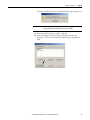
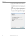
The IAB opening dialog box appears.
2. Click New Project.
20
Rockwell Automation Publication 1769-AP001B-EN-P - May 2015
Migration Considerations
Chapter 2
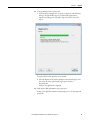
3. In the Workspace Name text box, type an appropriate name, such as ‘SLC
Migration Wizard’, and click OK.
4. Under Wizard View, click SLC Migration.
TIP
Clicking on the wizards listed under Available Assistants provides an overview
of the wizard.
Click for more information
about the wizard.
Rockwell Automation Publication 1769-AP001B-EN-P - May 2015
21
Chapter 2
Migration Considerations
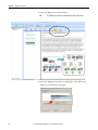
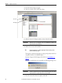
5. In the SLC Migration Chassis Selection dialog box, click Add Chassis.
IAB opens the Add Chassis dialog box.
6. Click OK to accept the default name (SLC001) for the new chassis.
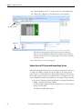
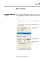
IAB opens the SLC Migration Module Selection dialog box. This is where
you make the conversion selections for this chassis. Notice the different
areas of this window.
Conversion Options
Original SLC Chassis
List of SLC Modules
Replacement CompactLogix Chassis
and Remote SLC I/O Chassis
7. Select your chassis size and choose power supply.
22
Rockwell Automation Publication 1769-AP001B-EN-P - May 2015
Migration Considerations
Chapter 2
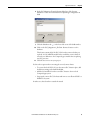
8. From the Processor module list, expand the Processor heading and drag
your processor module to slot 0 of the SLC chassis.
Because IAB has found more than one possible CompactLogix controller
migration option, the SLC Migration Conflict Resolution Dialog box
appears.
TIP
Conflict resolution dialogs appear when you must make a decision about the
conversion. The information in the dialog box is specific to the action you are
performing. In this case, we must select the CompactLogix processor that we
wish to use.
Rockwell Automation Publication 1769-AP001B-EN-P - May 2015
23
Chapter 2
Migration Considerations
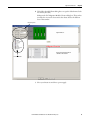
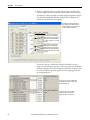
9. Select a processor in the list and click OK.
In this example, we show the 1769-L36ERM module.
IAB adds processors to both the SLC chassis and the replacement
CompactLogix chassis. Additionally, IAB also adds a 1747-AENTR
Ethernet adapter module to the retained I/O SLC chassis at the bottom of
the display.
1747-L553
1769-L36ERM
1747-AENTR
10. Repeat steps 8 and 9 to fill remaining slots.
TIP
If you incorrectly place a module, simply right-click the module and click
Remove Module to try again.
The majority of 1746 and 1747 discrete, analog, and specialty modules are
compatible with the 1747-AENTR adapter.
For a list of supported and unsupported modules, see I/O Modules on
page 75.
24
Rockwell Automation Publication 1769-AP001B-EN-P - May 2015
Migration Considerations
Chapter 2
If you have a module that is not compatible, the following warning occurs.
IMPORTANT
Modules not supported as part of a retained I/O solution, when connected to a
Logix controller, are not placed into the lower chassis in IAB.
11. Once the local SLC chassis is complete, click OK.
12. In the SLC Migration Chassis Selection dialog box, click Generate
Hardware to create the wizard-defined CompactLogix configuration in
IAB.
Rockwell Automation Publication 1769-AP001B-EN-P - May 2015
25
Chapter 2
Migration Considerations
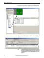
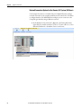
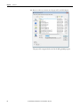
13. Click the Hardware tab
in the lower left corner of the IAB window.
14. Click the SLC_Migration.1_SLC001 chassis to see the hardware.
SLC_Migration.1_SLC001
Hardware Tab
This chassis contains all of the SLC I/O from the local rack that we
replaced. A 1747-AENTR module has been added to connect this I/O
remotely over Ethernet to the CompactLogix controller that is replacing
our SLC processor.
15. Click the save icon to save your project.
Replace the Local SLC System with CompactLogix System
Although retaining the SLC I/O when converting to a Logix system can save on
re-wiring costs, adding a controller and a power supply to an existing control
panel can prove to be impossible due to physical space limitations. In such cases,
the best SLC conversion solution can actually involve converting the I/O to the
1769 or POINT I/O™ platforms in addition to converting to a Logix controller.
1. Go to Start > Programs > Rockwell Automation > Integrated Architecture
Builder > Integrated Architecture Builder
or double-click the Integrated Architecture Builder icon on the computer
desktop to launch IAB.
The IAB opening dialog box appears.
26
Rockwell Automation Publication 1769-AP001B-EN-P - May 2015
Migration Considerations
Chapter 2
2. Click New Project.
The Create New Workspace dialog box appears.
3. In the Workspace Name text box, type an appropriate name, such as ‘SLC
Migration Wizard’, and click OK.
Rockwell Automation Publication 1769-AP001B-EN-P - May 2015
27
Chapter 2
Migration Considerations
4. Click SLC Migration in the Wizard View.
TIP
Click Available Assistants for more information about each assistant.
5. In the SLC Migration Chassis Selection dialog box, click Add Chassis.
IAB opens the Add Chassis dialog box.
28
Rockwell Automation Publication 1769-AP001B-EN-P - May 2015
Migration Considerations
Chapter 2
6. Click OK in the Add Chassis dialog box to accept the default name for the
new chassis (SLC001).
IAB opens the SLC Migration Module Selection dialog box. This is where
you make the conversion selections for this chassis. Notice the different
areas of this window.
Conversion Options
Original SLC Chassis
Replacement CompactLogix Chassis
and Remote SLC I/O Chassis
List of SLC Modules
7. Select your chassis size and choose power supply.
Rockwell Automation Publication 1769-AP001B-EN-P - May 2015
29
Chapter 2
Migration Considerations
8. From the Processor module list, expand the Processor heading and drag
your processor module to slot 0 of the SLC chassis.
Because IAB has found more than one possible CompactLogix controller
migration option, the SLC Migration Conflict Resolution Dialog box
appears.
TIP
30
Conflict resolution dialog boxes appear when you must make a decision about
the conversion. The information in the dialog box is specific to the action you
are performing. In this case, we must select the CompactLogix processor that
we wish to use.
Rockwell Automation Publication 1769-AP001B-EN-P - May 2015
Migration Considerations
Chapter 2
9. Select a processor in the list and click OK.
In this example, we show the 1769-L36ERM module.
IAB adds processors to both the SLC chassis and the replacement
CompactLogix chassis. Additionally, IAB also adds a 1747-AENTR
Ethernet adapter module to the retained I/O SLC chassis at the bottom of
the display.
1747-L553
1769-L36ERM
10. Repeat steps 8 and 9 to fill remaining slots.
TIP
If you incorrectly place a module, right-click the module and click Remove
Module to try again.
The majority of 1746 and 1747 discrete, analog, and specialty modules are
compatible with the 1747-AENTR adapter.
For a list of supported and unsupported modules, see I/O Modules on
page 75.
Rockwell Automation Publication 1769-AP001B-EN-P - May 2015
31
Chapter 2
Migration Considerations
If you have a module that is not compatible, the following warning occurs.
IMPORTANT
Modules not supported as part of a retained I/O solution, when connected to a
Logix controller, are not placed into the lower chassis in IAB.
11. Once the local SLC chassis is complete, click OK.
12. In the SLC Migration Chassis Selection dialog box, click Generate
Hardware to create the wizard-defined CompactLogix configuration in
IAB.
32
Rockwell Automation Publication 1769-AP001B-EN-P - May 2015
Migration Considerations
Chapter 2
13. Click the Hardware tab
in the lower left corner of the IAB window
and click the chassis to see the hardware.
Click your chassis
Hardware Tab
This chassis contains all of the SLC I/O from the local rack that was
replaced.
14. Click the save icon to save your project.
Adding a Chassis
If your system does contain additional remote chassis, you can add to the existing
chassis.
1. On the SLC Migration Chassis Selection dialog box, click Add Chassis.
This chassis replaces the remote SLC I/O chassis in your existing system.
2. Name this chassis, for example, SLC002_Remote, and click OK.
Rockwell Automation Publication 1769-AP001B-EN-P - May 2015
33
Chapter 2
Migration Considerations
3. Select the chassis and power supply.
4. Choose to retain the SLC I/O for this chassis.
Chassis Size
Add Modules
Power Supply
5. Add your remote I/O adapter module to slot 0 of the SLC chassis.
IMPORTANT
IAB replaces the 1747-ASB adapter with a 1747-AENTR Ethernet adapter in the
replacement SLC remote I/O chassis.
6. Add in the rest of your I/O modules.
TIP
If you incorrectly place a module, simply right-click the module and click
Remove Module to try again.
The majority of 1746 and 1747 discrete, analog, and specialty modules are
compatible with the 1747-AENTR adapter.
For a list of supported and unsupported modules, see I/O Modules on
page 75.
If you have a module that is not compatible, the following warning occurs.
IMPORTANT
Modules not supported as part of a retained I/O solution, when connected to a
Logix controller, are not placed into the lower chassis in IAB.
7. Once the remote SLC chassis is complete, click OK.
34
Rockwell Automation Publication 1769-AP001B-EN-P - May 2015
Migration Considerations
Chapter 2
8. In the SLC Migration Chassis Selection dialog box, click Generate
Hardware to create the wizard-defined CompactLogix configuration in
IAB.
9. Click the Hardware tab
in the lower left corner of the IAB window.
10. Click on the SLC_Migration.1_SLC002 - Remote chassis to see the
hardware.
This chassis contains all of the SLC I/O from the remote rack that you
replaced. A 1747-AENTR module has been added to connect this I/O
remotely over Ethernet to the CompactLogix controller that is replacing
our SLC processor.
11. Click the save icon to save your project.
You have three options when converting the second, remote chassis:
• To convert the local SLC I/O, leave the remote SLC chassis in place, add
the Ethernet wiring, and rebuild the BOM.
• Add the I/O modules from the second SLC chassis to the new local
CompactLogix system.
• Swap out the remote SLC I/O chassis with a more cost-effective FLEX™ or
POINT I/O system.
In either case, this is best done outside the wizard.
Rockwell Automation Publication 1769-AP001B-EN-P - May 2015
35
Chapter 2
Migration Considerations
Network Connection Options for the Remote (SLC System) I/O Chassis
Connecting I/O systems to a controller is best accomplished by first creating a
network connection on the controller itself. Because the remote SLC I/O chassis
is configured with a 1747-AENTR Ethernet adapter you can connect it to the
CompactLogix chassis by using an Ethernet network.
1. In the Hardware View for the SLC_Migration_SLC001.CpLX chassis,
right-click the controller and choose Connect > Connect ‘Port 1’ to a new
EtherNet/IP Network > Standalone Device Level Linear.
36
Rockwell Automation Publication 1769-AP001B-EN-P - May 2015
Migration Considerations
Chapter 2
2. Click OK to accept the default network name.
3. Click OK to choose default Copper media for the linear topology.
4. Set the IP address (reference only) of the CompactLogix controller and
click OK.
Rockwell Automation Publication 1769-AP001B-EN-P - May 2015
37
Chapter 2
Migration Considerations
IAB indicates that new connections on this Ethernet network is connected
to the CompactLogix controller.
5. Click OK.
6. Choose the Network tab.
Linear001 Tab
Network View
7. In the Network View, choose the Linear001 tab.
You see an icon representing the CompactLogix controller. You add your
remote I/O devices in this view.
8. Select an I/O adapter from the Ethernet device list tab and drag it into the
Network View window.
In this example we use the 1794-AENTR adapter module.
You can modify the characteristics of the adapter such as its IP address.
38
Rockwell Automation Publication 1769-AP001B-EN-P - May 2015
Migration Considerations
Chapter 2
9. Right-click the FLEX adapter and choose Channel properties.
10. Configure the IP address of the FLEX adapter and click OK.
Rockwell Automation Publication 1769-AP001B-EN-P - May 2015
39
Chapter 2
Migration Considerations
11. Add the I/O modules to this FLEX chassis.
If you need to expand the chassis size to accommodate your needs, follow
these steps.
a. Right-click the Flex001 adapter and choose Goto Chassis to reveal the
FLEX adapter in the Hardware View.
b. Right-click the FLEX adapter and choose Configure Chassis.
c. Set the value for the Number of Slots and click OK.
12. Save your project.
40
Rockwell Automation Publication 1769-AP001B-EN-P - May 2015
Migration Considerations
Chapter 2
Create Project Bill of Material
Follow these steps to get an idea of how much your conversion is going to cost
and what is needed.
1. From the Menu Bar, click the Project Bill of Material (BOM) icon.
Project Bill of Material
From this dialog box, we can get a clear view of the material necessary to
make the conversion based on the chassis layouts.
In addition, the radio buttons along the bottom of the dialog box let you
manipulate the information either as a consolidated spreadsheet or by slot
location. All of these arrangements incorporate pricing either with List or
Custom pricing models.
2. Click Close to close the BOM window.
Rockwell Automation Publication 1769-AP001B-EN-P - May 2015
41
Chapter 2
Migration Considerations
Notes:
42
Rockwell Automation Publication 1769-AP001B-EN-P - May 2015
Chapter
3
Conversion
Introduction
The Logix Designer application includes a RSLogix Project Migrator that
converts an SLC 500 import/export file (SLC extension) into a complete
import/export file (L5K extension) for the Logix Designer application.
TIP
The Studio 5000 environment, which includes the Logix Designer application,
was introduced in version 21. If you are using RSLogix 5000 software version
20, the steps are nearly identical.
This section describes the RSLogix Project Migrator Tool and also describes pretranslation file preparation and post-translation examples and tasks.
For a more detailed explanation of the RSLogix Project Migrator, refer to
Converting
PLC-5 or SLC 500 Logic to Logix-based Logic, publication 1756-RM085.
IMPORTANT
The process for converting an SLC system to a ControlLogix system is similar to
converting to a CompactLogix system.
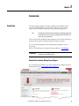
Download the standalone RSLogix Project Migrator
You can download a standalone copy of the RSLogix Project Migrator from the
Rockwell Automation Compatibility & Download page.
Rockwell Automation Publication 1769-AP001B-EN-P - May 2015
43
Chapter 3
Conversion
3. Under the Download option, click Find Downloads.
4. In the Product Search box, type RSLogix Project Migrator.
The migrator appears in the product list.
5. Select the RSLogix Project Migrator from the product list and then click
Downloads.
6. On the Downloads page, click the show downloads icon.
7. On the Available Downloads dialog, select the RSLogix Project Migrator
and click the Download Cart button and confirm your selection to start
the download.
44
Rockwell Automation Publication 1769-AP001B-EN-P - May 2015
Conversion
Chapter 3
What to Expect from the RSLogix Project Migrator
The goal of the RSLogix Project Migrator is to reduce the amount of work
involved in migrating an SLC 500 program to a Logix project. The RSLogix
Project Migrator automatically converts the program logic, but the tool is not the
complete solution. Depending on the application, you may need to do additional
work to make the converted logic work properly.
The RSLogix Project Migrator produces a syntactically correct import/export
file, but the exact intent of the original application could be lost. This loss could
be due to differences in rules. (For example, rules of precedence, rules of indexed
addressing, or rules of I/O addressing). When there is an error in the translation,
the RSLogix Project Migrator records the error in the rung of the Logix routine
in which it occurred. You can use that error message to analyze and fix the error.
ATTENTION: After running the conversion process, the resulting import/export file still
requires further manipulation. You have to map the I/O and use BTD, MOV, or CPS
instructions to place this mapped data into the structures created by the conversion
process.
Application Code Conversion
The first step in a procedure of this type is to export the current SLC project into
an ASCII text format.
1. From the desktop, double-click the RSLogix 500 programming software
icon.
Or, choose Start > All Programs > Rockwell Software > RSLogix 500 >
RSLogix 500.
2. From the File menu, choose Open to open the file you want to convert.
The first step is to export the current SLC project into an ASCII text
format.
3. From the File menu, choose Save As.
Rockwell Automation Publication 1769-AP001B-EN-P - May 2015
45
Chapter 3
Conversion
4. Browse to the folder where you are saving the converted program.
46
Rockwell Automation Publication 1769-AP001B-EN-P - May 2015
Conversion
Chapter 3
5. Set the file type to ‘.SLC.
The RSLogix Project Migrator accepts projects that have been saved as
.SLC file type.
Rockwell Automation Publication 1769-AP001B-EN-P - May 2015
47
Chapter 3
Conversion
6. Click Save to continue.
Additional file export options are presented. For this example, we want to
export the entire project, so the default settings here are fine.
7. Click OK.
After the file is converted, select the export options.
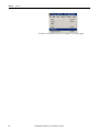
From the Tools menu, select Database >ASCII Export.
The Document Database ASCII Export window displays
48
Rockwell Automation Publication 1769-AP001B-EN-P - May 2015
Conversion
Chapter 3
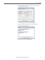
8. From the CSV tab, select Export Addr/Symbol Desc. and Instruction
Comments, and then click OK.
The Select Export Destination Directory dialog displays.
9. Browse to the folder where you saved the .slc file, and click OK.
The Export Result dialog displays.
10. Click OK to close the RSLogix 500 software.
Rockwell Automation Publication 1769-AP001B-EN-P - May 2015
49
Chapter 3
Conversion
Translate an RSLogix 500
Program to a Logix
Designer Program
The RSLogix Project Migrator is an optional install as part of the Logix Designer
application installation procedure. Once you have the ASCII text file of the SLC
500 program file, you can convert the logic to its Logix equivalent. In the Logix
Designer application, use the following steps.
1. Launch the tool from one of two locations:
• From the Windows Start Menu: Start > Programs > Rockwell Software
> Studio 5000 Tools > RSLogix Project Migrator
• From within the Logix Designer application: Tools >
RSLogix Project Migrator
The initial dialog box for the RSLogix Project Migrator appears.
2. Click For SLC-500/MicroLogix to Logix migration.
50
Rockwell Automation Publication 1769-AP001B-EN-P - May 2015
Conversion
Chapter 3
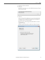
3. Click Browse and locate .SLC file.
4. Click open.
By default, the wizard expects to use the default documentation file names
that you exported earlier.
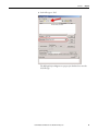
5. Click next.
In the second step of the translation process, you set the options for the
new project you are creating. The Create Alias Tag for existing PLC-5/
SLC Symbols option is selected by default.|
When this option is enabled, Logix5/500 symbols will be converted to
Logix5000 alias tags.
If disabled, symbols will instead be included in the address description.
Rockwell Automation Publication 1769-AP001B-EN-P - May 2015
51
Chapter 3
Conversion
Click Migrate.
If there are any syntax errors during migration, the Syntax Error dialog box
appears, showing the line in which the syntax error occurred.
6. Resolve any syntax errors by using any of the following actions:
• Edit the error immediately at this dialog box and then click Save & Retry
to restart the migration.
• Examine the original application to decide if the area where the syntax
error is occurring is something that can be deleted permanently or if it is
something that can be removed and then later be recreated in the
Logix Designer application.
• Edit the SLC and TXT files by using Notepad.
• Review this table for the most common syntax errors and their
descriptions.The migration tool can run into syntax errors within the
program and database files. If so, you must correct those errors so that the
migration tool can continue the conversion. Table 1 shows the more
common errors.
Table 1 - Common Conversion Errors
52
Syntax Error
Description
How to Fix the Error
Invalid symbol name
The RSLogix Project Migrator expects the
symbol names to be alphanumeric.
RSLogix 500 software enforces these rules, but
using 6200 software or manually editing the
database files can cause these rules to be
broken.
Search for symbol names that
are not alphanumeric.
" (quote) within a " (quote)
Quotes are used to denote the start and end of
string values or rung/instruction/address
comments.
If a rung/instruction/address comment
contains a quote, the RSLogix Project Migrator
doesn’t know that it isn’t the end of the string.
Either remove the quote or
make it a double quote ("").
The RSLogix Project Migrator
translates the double quote as
a single quote within the
Logix Designer application.
% within a %
% characters are used to denote the start and
end of comments within the program file and
occasionally in database files.
This type of comment is ignored by the RSLogix
Project Migrator. If a comment contains
another %, the RSLogix Project Migrator
doesn’t know that it isn’t the end of the
comment.
Remove the extra % or make it
a double %. The RSLogix
Project Migrator treats the
double %% as consecutive
comments.
Errant characters
The program or database file contains a
random character or two that does not fit the
syntax of the program or database files. This is
more common with manually-edited files than
a direct export from RSLogix 500 software.
Remove the errant characters.
Invalid rung syntax
The rung has invalid syntax, such as
unmatched parentheses.
Check and fix the rung syntax.
Rockwell Automation Publication 1769-AP001B-EN-P - May 2015
Conversion
Chapter 3
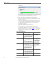
7. Once these errors have been resolved, click Save & Retry.
The parsing is completed as shown below.
8. Click Next to select the output file options.
In Step 4, specify the RSLogix 5000 file name you wish to create and where
you want to save it, which controller type you are using the output file for,
and which version you are using.
Click Browse...
9. Browse to the folder where you want to save the file.
Rockwell Automation Publication 1769-AP001B-EN-P - May 2015
53
Chapter 3
Conversion
10. From the Controller Type pull down menu, select the controller that you
want to use the output file with, and then select the version number.
11. Click Next.
In Step 5, decide if you want to keep your existing I/O set up on a separate
rack and put your new controller on a rack with a single bridge module; or,
if you want to replace all existing I/O modules with newer equivalent
modules.
If you choose to keep your existing I/O, any module that is unsupported by
the newer controller generates a placeholder tag in the migrated output
file.
If you choose to replace all your existing I/O modules with equivalent
newer modules, you need to select replacements from a list of suggested
modules.
54
Rockwell Automation Publication 1769-AP001B-EN-P - May 2015
Conversion
Chapter 3
12. To keep existing I/O in a separate rack
a. Select the Keep existing I/O in a separate rack option, and click Next.
In Step 6, the placeholder tags are created and the application is
migrated according to the Controller Type and version selected in
Step 4.
To replace all I/O with equivalent newer models
b. Select the Replace all I/O with equivalent newer models option, and
then select the Create placeholder tag(s) option from the
drop down list.
In Step 6, the application is migrated.
13. Click Launch RSLogix 5000 to start your project.
In Step 7, the application launches and prompts you to save the imported
project file.
Rockwell Automation Publication 1769-AP001B-EN-P - May 2015
55
Chapter 3
Conversion
14. Browse to where you want to save the project file, and click Import.
The project file is migrated and created in the RSLogix5000 program.
56
Rockwell Automation Publication 1769-AP001B-EN-P - May 2015
Conversion
Resolve the Differences in
the New Logix Program
Chapter 3
Now that the SLC 500 program has been initially converted to a Logix program,
you need to look at some of the most common elements that must be addressed
for the CompactLogix project to properly control the installed 1746 I/O
modules.
TIP
See Appendix B for supported and unsupported I/O modules.
SLC Controllers Data Tables and Logix Controller Tags
The SLC 500 processors store all data in global data tables. You access this data by
specifying the address of the data you want. A Logix controller supports data that
is local to a program and data that is global to all the tasks within the controller. A
Logix controller can also share data with other controllers, and instead of
addresses, you use tags to access the data you want. Each SLC 500 data table file
can store several words of related data. A Logix controller uses arrays to store
related data. The RSLogix Project Migrator converts the SLC 500 data table files
into Logix arrays.
With a Logix controller, you use a tag (alphanumeric name) to address data
(variables). The controller uses the tag name internally and does not need to
cross-reference a physical address.
• In conventional programmable controllers, a physical address identifies
each item of data.
– Addresses follow a fixed, numeric format that depends on the type of
data, such as N7:8, F8:3.
– Symbols are required to make logic easier to interpret.
• In Logix controllers, there is no fixed, numeric format. The tag name itself
identifies the data.
– Organize your data to mirror your machinery.
– Document (through tag names) your application as you develop it.
Resolve Program Code Issues
The RSLogix Project Migrator inserts a Program Conversion Error (PCE)
instruction within the appropriate ladder rung to help you identify possible
errors with the conversion. To complete the conversion process, you want to
locate, analyze, and fix any discrepancies involving the PCE instructions.
TIP
IMPORTANT
For a complete list of the PCE instruction Message IDs and their descriptions,
please refer to Appendix A.
After the correction of any errors, you must still spend time running and
debugging the machine or process.
Rockwell Automation Publication 1769-AP001B-EN-P - May 2015
57
Chapter 3
Conversion
Locating PCE Instructions
You can locate all of the PCE instructions by verifying the logic. The
Verify>Controller task compiles the Logix program and checks for errors. This is
an easy way to see where all of the PCE instructions are because the error
checking points them out. To locate the PCE instructions, use the following
steps.
1. From the Logic menu, choose Verify> Controller.
Or, from the menu bar, choose the Verify Routine icon.
The bottom of the dialog box displays results.
2. Double-click the error shown in the error window to go directly to the
rung where the error occurred.
TIP
58
Some Warnings reference bits that are used as outputs in more than one rung,
Duplicate Destructive Bits. While using this type of coding is generally not
recommended, with careful programming, using the same outputs on several
different rungs can be done.
Rockwell Automation Publication 1769-AP001B-EN-P - May 2015
Conversion
Chapter 3
Recognizing the Instructions
Text is appended to the rung comments that have the PCE instruction. The
message text begins with asterisks(*) and the words “Generated by RSLogix
Project Migrator”, and ends with asterisks.
An example of a PCE instruction follows:
*** Generated by RSLogix Project Migrator: Source and destination types may
differ *** ";
N: PCE(120, PCE011) COP(I1_008, N23[0], 4);
Resolving PCE Instructions
Once you import the converted Logix project, find each PCE instruction. A
PCE instruction highlights a possible conversion error. Delete each PCE
instruction and replace it with the appropriate, corrected logic.
Common PCE Issues
Translation greatly reduces the amount of work in a conversion; however, you
may still get conversion errors that must be addressed individually.
• A very common error occurs with all Timer related instructions. The timer
instruction and its associated elements are compatible between the SLC
500 controller and the Logix platform. However, the SLC 500 controller
supports only a .01 or 1 second time base for timers. Logix controllers
support a 1 ms time base. The code conversion resulted in an increase of
the timer Preset value by an order of magnitude. That is, the original Preset
in the SLC 500 controller for this timer was 32767 and now it has been
changed to 327670. All related references to this timer have been adjusted
automatically, except those that reference a specific bit within the Accum
or Preset itself. This can lead to errors on any rung that addresses a
Timer.PRE or Timer.ACC because the scaling can be off and can be
corrected only by user intervention.
• Another common conversion tool error is related to MSG instructions.
Not all SLC 500 MSG instructions convert completely and, after the
conversion, you need to verify that the data and path in all MSG
instructions are correct.
Rockwell Automation Publication 1769-AP001B-EN-P - May 2015
59
Chapter 3
Conversion
• Several other SLC instructions may not convert properly or may not have
the intended behavior. Among the more significant SLC instructions that
can have issues are serial port instructions, Block Transfer instructions,
FBC, and PID.
60
Rockwell Automation Publication 1769-AP001B-EN-P - May 2015
Conversion
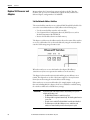
Map PLC/SLC Messages
Chapter 3
Map PLC/SLC Messages is a built-in feature of Logix controllers that lets older
products that support a data table memory architecture, like PLC-2,
PLC-5, and SLC controllers read/write to a Logix controller that has a
tag-based memory architecture.
If after the conversion, legacy SLC controllers need to communicate to the
converted Logix controller, Map PLC/SLC Messages can facilitate this. See the
example below for an overview explaining PLC/SLC Mapping.
EXAMPLE
If an incoming message from an SLC controller requests to read data from file
N7:x, the Logix controller replies with data from tag
SLC_Reads_This_LogixTag[x].
If an incoming message from an SLC controller requests to write data to file
N10:x, the Logix controller places that data in tag
SLC_Writes_to_This_LogixTag[x].
Rockwell Automation Publication 1769-AP001B-EN-P - May 2015
61
Chapter 3
Conversion
Resolving Issues with
Physical I/O
Remember, in your new CompactLogix system, all of the 1746 I/O is considered
remote, but you are not using remote I/O. Each SLC chassis is connected
through the 1747-AENTR Ethernet adapters. This eliminates quite a bit of extra
code otherwise required to communicate to remote I/O.
There are three options for resolving physical I/O issues:
• MOV instructions
• CPS instructions
• Aliasing instructions
Each has its advantages and drawbacks depending on the type of data. Ideally, the
RSLogix Project Migrator identifies I/O to be converted and offers you options
during the conversion process rather than leaving this to you afterwards.
These examples illustrate situations you can encounter when translating your
files.
MOV Example
This first rung is used to initialize the configuration for a 1746-NT4 module in
slot 5 of the local SLC 500 chassis.
The Dest data location represents an integer array of at least 4 elements. To
successfully configure multiple channels, the normally consecutive array elements
must be transferred into non-consecutive structures built by the 1746-NT4
module data type.
The original rung can remain, but you need to create a new rung that moves the
configuration for the channel to the corresponding module config tag.
This resolves the issue for Channel 0. Additional MOV instructions are required
if other channels are used.
62
Rockwell Automation Publication 1769-AP001B-EN-P - May 2015
Conversion
Chapter 3
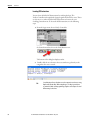
CPS Example
In RSLogix 500 software in order for many specialty modules to transfer data
over RIO, sophisticated instructions called Block Transfers were used. In the
Logix Designer application, these Block Transfers were replaced with the MSG
instructions shown below.
The need for messaging to/from these modules is no longer needed because the
controller is communicating with them directly through the 1747-AENTR
module.
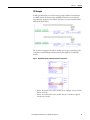
Figure 3 - Original RSLogix 500 Software Block Transfer Instructions
• Data to be written to the remote module in our example, was entered into
N11:0 (2 words).
• Data to be read from the remote module into the controller was placed
into N13:0 (2 words).
Rockwell Automation Publication 1769-AP001B-EN-P - May 2015
63
Chapter 3
Conversion
If consecutive I/O groups map to consecutive elements in an array, a CPS
instruction must be used. Use a CPS instruction when you copy I/O or
Produced/Consumed peer data of more than one DINT. This is the only
information you need to create the instructions necessary to replicate the original
program functionality.
IMPORTANT
Extensive use of the CPS instruction can lock the tag database which could
affect other processes.
You can delete the rungs containing the PCE and MSG instructions and replace
them with CPS rungs.
The CPS instruction moves data from the array titled N11, which is used throughout the program, to the
1747-I/O module.
The CPS Instruction moves data from the 1747-I/O module to the array titled N13. N13 is used throughout
the program.
IMPORTANT
64
The CPS instruction is intended to be used when copying I/O data or Produced/
Consumed peer data to/from controller tags. For more information on the use
of the CPS instruction, see Knowledgebase document KB ID 50235, contact
your local Allen-Bradley distributor, or Rockwell Automation sales
representative.
Rockwell Automation Publication 1769-AP001B-EN-P - May 2015
Conversion
Chapter 3
Alias Example
The rung in this routine uses a timer accumulator to simulate an analog output
value for a 1746 I/O module. Although this is not very realistic, it does provide
an instance in which aliasing can be most used.
In the example rung, a value is being moved into the O3_000 ‘alias’ tag generated
by the RSLogix Project Migrator. However, you need to actually tie this tag to a
physical output address, namely the output location associated with the 1746 I/
O module.
Aliasing the T4[30].ACC to the physical output address can seem like the right
choice, but members of an array cannot be aliased in Logix. Because this
instruction manipulates just a single word of data, you can modify the MOV
instruction. Based on the I/O configuration, the base output data for the local
1746 I/O module is contained in the ‘Adapter_1:x:O’ tag.
You need to modify the Dest element of the MOV instruction and delete the
PCE instruction.
Rockwell Automation Publication 1769-AP001B-EN-P - May 2015
65
Chapter 3
Conversion
Replace SLC Processor and
Adapters
Mount and wire the CompactLogix system and replace the SLC first slot
modules (SLC processor or communication adapter module) with the SLC
Ethernet adapter, catalog number 1747-AENTR.
Set the Network Address Switches
The network address switches are set to 999 and DHCP enabled, by default. You
can set the network Internet Protocol (IP) address in the following ways:
• Use the network address switches on the module.
• Use a Dynamic Host Configuration Protocol (DHCP) server, such as
Rockwell Automation BootP/DHCP.
• Retrieve the IP address from nonvolatile memory.
The adapter reads the network address switches first to determine if the switches
are set to a valid number. You set the node address by using the network address
switches. Valid settings range from 001…254.
When the switches are set to a valid number, the adapter’s IP address is
192.168.1.xxx (where xxx represents the number set on the switches).
The adapter’s subnet mask is 255.255.255.0 and the gateway address is set to
0.0.0.0. The adapter does not have a host name assigned, or use any Domain
Name System when using the network address switch settings.
If the switches are set to an invalid number (for example, 000 or a value greater
than 254 excluding 888), the adapter checks to see if DHCP is enabled. Setting
the switches to 888 restores default factory settings.
IMPORTANT
66
If you set the value of the adapter switch to 888 and then power cycle the
module, the following occurs:
• The DHCP Enabled function is enabled (set to True).
• The Ethernet link is negotiated automatically. The Auto Negotiate function
is set to True.
• The web server is enabled. The Disabled Web Server function is disabled.
• The Ethernet ports are disabled. Both ports are re-enabled once the
switches are returned to their previous value and power is cycled.
Rockwell Automation Publication 1769-AP001B-EN-P - May 2015
Conversion
Chapter 3
DHCP Enabled and Not Enabled
DHCP Enabled and Not Enabled
If DHCP is
Then the Adapter
Enabled
Asks for an address from a DHCP server. The DHCP server also assigns other Transport Control
Protocol (TCP) parameters.
The 1747-AENTR factory default is DHCP enabled. When you apply power, the module sends a
message containing its hardware address to any DHCP server on the network. The server(s)
replies by sending a message with an appropriate IP address for the adapter. The adapter
responds by acknowledging to a server that the adapter will use the offered IP address.
Not enabled
Uses the IP address (along with other TCP configurable parameters) stored in nonvolatile
memory.
When the IP address assigned to the module, as indicated in the four-character dot matrix status
display, is changed through the DHCP configuration utility, the DHCP is disabled.
When power is cycled to the device, the device uses the new configuration and implements the
new IP address.
Determine Power Requirements
The Ethernet adapter requires 5V DC with current consumption of 470 mA.
The power is supplied through backplane from SLC power supply. Remember to
consider this requirement when planning your system configuration.
Install the Adapter Module in the Chassis
After you set the appropriate switch assemblies for your adapter module, follow
these procedures for installation.
Refer to the Industrial Controller Wiring and Grounding Guidelines publication
1770-4.1 for proper grounding and wiring methods to use when installing your
module.
1. Remove power from the I/O chassis before inserting (or removing) the
module.
Rockwell Automation Publication 1769-AP001B-EN-P - May 2015
67
Chapter 3
Conversion
2. Align the circuit board with the chassis card guide in the left slot.
3. Install the module in slot 0 of the chassis by aligning the circuit board with
the chassis card guide.
The 1747-AENTR module must be installed only in slot 0 (leftmost slot)
of the chassis.
4. Press firmly and evenly to seat the module in its backplane connectors.
To remove the module, press the releases at the top and bottom of the
module and pull it out.
ATTENTION: Do not force the module into the backplane connector. If you
cannot seat the module with firm pressure, check the alignment. Forcing the
module can damage the backplane connector or the module.
68
Rockwell Automation Publication 1769-AP001B-EN-P - May 2015
Conversion
Chapter 3
Connect Your Adapter to the Ethernet/IP Network through RJ45
Connection
Connect your 1747-AENTR adapter module to an Ethernet/IP network as
shown below.
Wire the RJ45 connectors as shown.
Signal
1
TxData+
2
TxData-
3
Recv Data+
4
Reserved
5
Reserved
6
Recv Data-
7
Reserved
8
Reserved
RJ45 connectors
RJ45
1
8
8
1
45844
1747-AENTR module bottom view
To connect the module to the network, follow these steps.
WARNING: If you connect or disconnect the communication cable with power
applied to this module or any device on the network, an electrical arc can occur.
This could cause an explosion in hazardous location installations. Be sure that
power is removed or the area is nonhazardous before proceeding.
1. Attach the cables with the RJ45 connectors to the two Ethernet ports on
the bottom of the module.
Rockwell Automation Publication 1769-AP001B-EN-P - May 2015
69
Chapter 3
Conversion
2. Attach the other end of the cables to the devices in your network.
CompactLogix
L33ERM
RUN
FORCE
NS
LINK 1
I/O
LINK 2
OK
SD
RUN
REM
PROG
Ethernet
XX:XX:XX:XX:XX:XX
1 (Front)
2 (Rear)
PanelView Plus
1747-AENTR
1747-AENTR
3. Configure your 1747-AENTR adapter.
See publication 1747-UM076 for information on configuring and using
your adapter.
Replace Other Components
If your control system has legacy or competitive operator interface, variable
frequency drives, motion control, sensors, or motor control centers, you can
migrate those products as well.
CompactLogix
PanelView Plus
L33ERM
RUN
Stratix 5700
NS
FORCE
LINK 1
I/O
LINK 2
OK
SD
RUN
REM
PROG
XX:XX:XX:XX:XX:XX
1 (Front)
2 (Rear)
Ethernet
C
A
B
D
E
1747-AENTR
1747-AENTR
MEM
300
ETHERNET
A=ENABLE
B= REGEN
C=DATA ENTRY
D=FAULT
E=COM ACTIVITY
24VDC
INPUT
MORTOR FEEDBACK
BRAKE/
DC BUS
Kinetix 350
70
PanelView Plus
PanelView Plus
Rockwell Automation Publication 1769-AP001B-EN-P - May 2015
PowerFlex 70E
Conversion
Chapter 3
See the following publications for more information:
• PanelView Plus Terminals
– For selecting your terminal: VIEW-SG001
– For installing and operating your terminal: 2711P-UM001
• PowerFlex Drives
– For selecting your drive: PLEX-SG002
– PowerFlex® 700S Adjustable Frequency AC Drive - Phase II Control
(Frames 1…6) Installation Instructions, publication 20D-IN024.
Provide information needed to install and wire a PowerFlex 700S Phase
II Adjustable Frequency AC drive.
– PowerFlex® 700H Adjustable Frequency AC Drive / PowerFlex 700S
High Performance AC Drive, Frames 9...14 Installation Instructions,
publication PFLEX-IN006. Provides drive mounting and wiring
information.
– PowerFlex 700S High Performance AC Drive- Phase I Control
Reference Manual, publication PFLEX-RM002 Provides information
on specifications and dimensions, mounting, and detailed drive
operation for the PowerFlex 700S with Phase I control.
– PowerFlex 700S High Performance AC Drive - Phase II Control
Reference Manual, publication PFLEX-RM003 Provides information
on detailed drive operation for the PowerFlex 700S with Phase II
control.
– PowerFlex 700S High Performance AC Drive - Phase II Control
Programming Manual, publication 20D-PM001 Provides information
needed to start-up, program and troubleshoot PowerFlex 700S Phase II
Adjustable Frequency AC drives.
– PowerFlex 700S with Phase II Control Technical Data, publication
20D-TD002 Provides information on options, specifications, ratings,
dimensions, derating data, and other product information.
– PowerFlex 700H Adjustable Frequency AC Drive Programming
Manual, publication 20C-PM001 Provides basic information needed
to start-up, program and troubleshoot the PowerFlex 700H Adjustable
Frequency AC Drive.
– Wiring and Grounding Guidelines for Pulse Width Modulated
(PWM) AC Drives, publication DRIVES-IN001 Provides basic
information needed to properly wire and ground PWM AC drives.
• Kinetix Motion Control
– For information about motion control: GMC-SG001
Rockwell Automation Publication 1769-AP001B-EN-P - May 2015
71
Chapter 3
72
Conversion
Rockwell Automation Publication 1769-AP001B-EN-P - May 2015
Appendix
A
Program Conversion Errors (PCE) Messages
Introduction
Table 2 lists all of the messages that are generated with a PCE instruction. The
text is appended to the rung comments that have the PCE instruction. The
message text begins with asterisks (*) and the words “Generated by RSLogix
Project Migrator”, and ends with asterisks.
Table 2 lists the message identifiers, descriptions, and when they are logged.
Table 2 - PCE Messages
ID
Text
When logged
101
The address references a counter’s Update Accum (UA) bit field. This is not
supported in the Logix Designer application.
Each time a reference to a counter’s UA field is encountered (SLC only)
102
The address references a counter’s Overflow(OV) or Underflow(UN) field. This has
been translated but the translation needs to be validated.
Each time a reference to a counter’s OV or UN field is encountered
103
Warning: Status files do not exist in the Logix Designer application. GSV
instructions are used in the Logix Designer application to obtain controller
information where applicable. This translation must be validated.
Each time a reference to the S file is encountered
105
The address references an indirect file number. It was not translated.
Each time an address reference with an indirect file number is encountered
107
The address reference may have an incorrect index. The translation needs to be
validated.
Each time suitable index into the array could not be determined
108
The BTR, BTW or MSG instruction has been translated. However, the translation
needs to be validated. These instructions have many parameters that cannot be
directly translated and require review.
Each time a BTR, BTW or MSG instruction is translated
109
PLC-5 and SLC s use 0.01 second and 1 second timebases. the Logix Designer
application uses a 0.001 second time base. The address references a ’s Accumulator
(ACC) field. The translation needs to be validated.
Each time a reference to a ’s ACC field was encountered
110
PLC-5 and SLC s use 0.01 second and 1 second timebases. the Logix Designer
application uses a 0.001 second time base. The address references a ’s Preset (PRE)
field. The translation needs to be validated.
Each time a reference to a ’s PRE field was encountered
113
Follow the <FBC or DDT> instruction with MOV and FAL instruction on parallel
branches to make sure the correct bits are being operated on.
Each FBC and DDT instruction
114
Although the PID instruction has been translated, the PID instruction has many
parameters that do not translate directly to the Logix Designer application. The
translation must be verified.
Each time a PID instruction is translated
115
16-bit parameters have been extended to 32-bit. Verify bit manipulation is correct. Each time BSL, BSR, BTD instruction is translated
116
The structure of FOR/NXT/BRK statements has changed in the Logix architecture. In
the PLC-5 processor, the FOR and NXT instruction enclosed a section of code that
was to be iterated multiple times, while the BRK instruction provided a way to
break out of the repeating code.
In the RSLogix architecture, the FOR instruction calls a given routine a specific
number of times, so a NXT instruction is not needed. The BRK instruction works in a
similar fashion as in the PLC-5 processor. Because this architecture change is
significant, you may need to restructure your logic.
Each time FOR/NXT/BRK instructions are encountered
117
AGA instruction not supported.
Each time a AGA instruction is found
119
CIR/COR not supported.
Each time a CIR or CIO instruction is found
Rockwell Automation Publication 1769-AP001B-EN-P - May 2015
73
Appendix A
Program Conversion Errors (PCE) Messages
Table 2 - PCE Messages
ID
Text
When logged
120
Source and destination types differ
When source and destination types differ in a COP instruction
121
DFA instruction not supported
Each time a DFA instruction is found
122
ERI/ERO instruction not supported.
Each time a ERI or ERO instruction is found
123
IDI/IDO instruction not supported.
Each time a IDI or IDO instruction is found
124
IIN/IOT instruction not supported.
Each time a IIN or IOT instruction is found
128
SFC routines aren’t translated.
Each time a SFR or EOT instruction is found
129
Online edit instructions are not supported.
Each time a SDS, SIZ or SRZ instruction is found
130
User Interrupt instructions not supported.
Each time a UID, UIE or UIF instruction is found
131
DDV instruction not supported.
Each time a DDV instruction is found
132
High Speed Counter instructions not supported.
Each time a HSC/HSD/HSE/ SL or RHC/RAC/TDF instruction is found
133
I/O Interrupt Enable/Disable instructions not supported.
Each time a IID or IIE instruction is found
134
IIM/IOM instruction not supported.
Each time a IIM or IOM instruction is found
135
INT instruction not supported.
Each time a INT instruction is found
136
REF instruction not supported.
Each time a REF instruction (in SLC) is found
137
RPI instruction not supported.
Each time a RPI instruction is found
138
Selectable Timed Interrupt instructions not supported.
Each time a STD/STE or STS instruction is found
139
SUS instruction not supported.
Each time a SUS instruction is found
141
RMP instruction not supported.
Each time a RMP instruction is found
142
RPC instruction not supported.
Each time a RPC instruction is found
143
SVC instruction not supported.
Each time a SVC instruction is found
144
SWP instruction not supported.
Each time a SWP instruction is found
145
SQC instruction not supported.
Each time a SQC instruction is found
146
INV instruction not supported.
Each time a INV instruction is found
147
DCD/ENC instruction not supported.
Each time a DCD or ENC instruction is found
148
The CEM, DEM, or EEM instruction has been translated. However, the translation
needs to be validated. These instructions have many parameters that cannot be
directly translated and require review.
Each time a CEM, DEM or EEM instruction is found
149
Modbus messaging is not supported in the Logix Designer application.
If MSG instruction is configured for Modbus
150
MSG instruction and associated MESSAGE tag need to be manually verified.
Each time a MSG instruction is found
151
WARNING: Status files do not exist in the Logix Designer application.
However this status file value is handled through the StatusFile routine.
S file type indexes that can be directly translated to functionality in the Logix
Designer application
152
the Logix Designer application has a different fault handling mechanism than the
PLC-5/SLC. This fault routine will not be called.
Start of identified legacy processor fault routine
153
This PII/DII routine is not used by the Logix Designer application.
Start of identified legacy processor PII/DII routine
74
Rockwell Automation Publication 1769-AP001B-EN-P - May 2015
Appendix
B
I/O Modules
Supported I/O Modules
The majority of 1746 and 1747 discrete, analog, and specialty modules are
compatible with the 1747-AENTR adapter.
Table 3 provides a list of supported modules.
Table 3 - I/O Modules Supported by the 1747-AENTR Adapter
Catalog
Number
Type
Catalog
Number
Type
1746-IA4
AC Digital Input Module
1746-OG16
DC Digital Output Module
1746-IA8
AC Digital Input Module
1746-OV8
DC Digital Output Module
1746-IA16
AC Digital Input Module
1746-OV16
DC Digital Output Module
1746-IB8
DC Digital Input Module
1746-OV32
DC Output Module
1746-IB16
DC Digital Input Module
1746-OVP16
DC Digital Output Module
1746-IB32
DC Input Module
1746-OW4
AC/DC Relay Output Module
1746-IC16
DC Digital Input Module
1746-OW8
AC/DC Relay Output Module
1746-IG16
DC Digital Input Module
1746-OW16
AC/DC Relay Output Module
1746-IH16
DC Digital Input Module
1746-OX8
AC/DC Relay Output Module
1746-IM4
AC Digital Input Module
1746-FIO4I
Analog Combination Module
1746-IM8
AC Digital Input Module
1746-FIO4V
Analog Combination Module
1746-IM16
AC Digital Input Module
1746-INT4
Thermocouple Isolated Input
Module
1746-IN16
AC/DC Digital Input Module
1746-NI4
Analog Input Module
1746-IO4
Digital Combination Module
1746-NI8(1)
Analog Input Module
1746-IO8
Digital Combination Module
1746-NIO4I
Analog Combination Module
1746-IO12
Digital Combination Module
1746-NIO4V
Analog Combination Module
1746-IO12DC Digital Combination Module
1746-NO4I
Analog Output Module
1746-ITB16
DC Digital Input Module
1746-NO4V
Analog Output Module
1746-ITV16
DC Digital Input Module
1746-NR4
RTD/Resistance Input Module
1746-IV8
DC Digital Input Module
1746-NT4
Thermocouple/mV Input Module
DC Digital Input Module
1746-NI16V(1)
Analog Input Module
DC Digital Input Module
1746-NI16I(1)
Analog Input Module
1746-OA8
AC Digital Output Module
1746-NR8(1)
RTD/Resistance Input Module
1746-OA16
AC Digital Output Module
1746-NT8
Thermocouple/mV Input Module
AC Digital Output Module
1746-NO8I(1)
Analog Output Module
1746-OB6EI
DC Digital Output Module
1746-NO8V(1)
Analog Output Module
1746-OB8
DC Digital Output Module
1746-HSTP1
Stepper Controller Module
1746-IV16
1746-IV32
1746-OAP12
Rockwell Automation Publication 1769-AP001B-EN-P - May 2015
75
Appendix B
I/O Modules
Table 3 - I/O Modules Supported by the 1747-AENTR Adapter
Catalog
Number
Type
Catalog
Number
Type
1746-OB16
DC Digital Output Module
1746-HSCE(2)
(1)
High-Speed Counter Module
Multi-Channel High-Speed
Counter Module
1746-OB16E
DC Digital Output Module
1746-HSCE2
1746-OB32
DC Digital Output Module
1746-QS(2)
Synchronized Axes Control
Module
1746-OB32E
DC Digital Output Module
1746-OBP16
DC Digital Output Module
DC Digital Output Module
1746-BAS/B(1)(2)
BASIC Module
(1)(2)
BASIC Module
1746-OBP8
1746-BAS-T
(1) This module supports multiple operating classes. The 1747-AENTR adapter automatically promotes multiclass
modules to the highest supported class. The 1746-NI16I, 1746-NI16V, 1746-NR8, 1746-NI8, 1746-NO8I, 1746NO8V modules are promoted from class 1 to class 3. The 1746-BAS/B, 1746-BAS-T, and 1746-HSCE2 modules
are promoted from class 1 to class 4.
(2) This specialty module uses Advanced module connection. Refer to the user manual specific to the I/O module to
learn about its connection configuration requirements.
Unsupported I/O Modules
76
Table 4 lists unsupported modules. You can also have third-party SLC I/O
modules in your system. Contact the third-party supplier to determine their
product's compatibility. In general, third-party modules can be supported as long
as the modules use fewer than 250 integer words and do not use G-files.
However, a new EDS file needs to be developed to make the third-party module
compatible with the 1747-AENTR adapter. If these modules are used in the
current system, other plans must be made to incorporate the modules into a
Logix system.
Rockwell Automation Publication 1769-AP001B-EN-P - May 2015
I/O Modules
Appendix B
Consult the SLC EtherNet/IP Adapter Module user manual, publication
1747-UM076 for the latest list of supported and unsupported modules.
Table 4 - I/O Modules NOT Supported by the 1747-AENTR Adapter
Catalog Number
Type
1746-HSRV
Servo Control Module
1746-BTM(1)
1747-DCM1
(1)
1747-DCM2
(1)
Barrel Temperature Module
Direct Communication Modules
1747-DCM3(1)
1747-DCM4(1)
1747-KE/A(1)
DH-485/RS-232C Interface Modules
1747-KE/B(1)
1747-KFC15
ControlNet to RS-232C Interface Module
1747-SDN/D(1)
DeviceNet Scanner module
1747-SCNR(1)
ControlNet Scanner module
1747-SN
Remote I/O Scanner Module
1747-BSN
Back-Up Remote I/O Scanner Module
1746-QV
Open Loop Velocity Control Module
1746-BLM
Blow Molding Module
1746-MPM
Mold Pressure Module
1203-SM1(1)
Scanport Module (Class 4 operation)
(1) The module is not supported by the 1747-AENTR but appears in the the
Logix Designer application pick list (Select Module Type dialog box).
IMPORTANT
Any 1746/1747 module that is not included in the lists of supported and
unsupported modules is not supported by the 1747-AENTR, as of the
date of writing of this user manual.
Consult the manufacturer of any third-party module to determine if the
module is supported by the 1747-AENTR adapter.
Rockwell Automation Publication 1769-AP001B-EN-P - May 2015
77
Appendix B
I/O Modules
Notes:
78
Rockwell Automation Publication 1769-AP001B-EN-P - May 2015
Appendix
C
Performance Expectations
The data provided here was gathered by using real world testing and is provided
as a guide to help you determine your expected results. The system consisted of a
1769-L36ERM module and a rack of 1746 I/O modules of different sizes and
types. No two systems are alike and your system may be different than shown
here. Use this data to help manage your performance expectations.
• Testing goal was to keep both the 1769-L36ERM % CPU and the
1747-AENTR % CPU under approximately 70%.
• Each user I/O module configuration is unique in terms of number and
types of modules within the chassis. Test results vary based on exact chassis
configuration.
• The data was gathered with all modules contained in a single 1746 chassis.
• RPIs of the various modules within the chassis do not need to be equal.
You can adjust individual module RPIs to meet your application needs.
The RPIs used in these tests were to extremely tax the system. Using RPIs
of 2 and 4 mS is not considered typical.
Table 5 - Performance - For Reference Only
Modules in chassis, tested to max size chassis 13 slots
1 - 1747-AENTR module
12 - I/O modules
1 - 1746-IB16
1 - 1746-OB16
(best case throughput)
1 - 1746-BAS
2 - 1746-NT4
2 - 1746-IB16
2 - 1746-OB16
1 - 1746-BAS
2 - 1746-NT4
5 - 1746-IB16
4 - 1746-OB16
All modules configured for same RPI
2 ms
2 ms
4 ms
Total number of INPUT bytes transferred across backplane
12
212
244
Total number of OUTPUT bytes transferred across backplane
4
184
192
L36ERM % Ethernet CPU, I/O Comms Utilization (Actual)
20%
71.5%
60.8%
1747-AENTR % CPU
23%
68%
66%
1747-AENTR backplane scan time Max/Avg
2 ms/2 ms
5 ms/5 ms
5 ms/5 ms
Typical discrete throughput with minimal Logix program scan (less than 1 ms)
7…11 ms
11…19 ms
12…19 ms
Typical discrete throughput with 15 ms Logix program scan
7…39 ms
12…47 ms
12…50 ms
Typical discrete throughput with 30 ms Logix program scan
9…70 ms
12…76 ms
11…85 ms
While the Logix controller might not scan the I/O in the 1747-AENTR chassis
as quickly as the SLC scans the I/O as local I/O, you may still see an overall
performance improvement after the conversion to Logix because you are likely to
see a significant program scan time decrease.
Rockwell Automation Publication 1769-AP001B-EN-P - May 2015
79
Appendix C
Performance Expectations
IMPORTANT
Logix Designer application version 21 and later, and 1747-AENTR module
firmware revision 2.001 and later, support configurations of multiple physical
1746 chassis connected by cables and scanned by a single 1747-AENTR
module. Multi-chassis support lets you use up to 3 physical chassis, with a
maximum of 30 I/O slots, scanned by a single 1747-AENTR module.
The 1747-AENTR firmware revisions prior to revision 2.001 support only a
single physical chassis and 13 I/O slots maximum.
When the 1747-AENTR module is used in a multi-chassis system you can expect
slower performance than the data presented in Table 5. The backplane scan time
can increase by as much as 35% especially in systems with a large number of Input
and Output bytes transferred across the backplane. The minimum RPI is also
affected by the number of I/O modules within the chassis. For a 30-I/O-module
chassis, the RPI must be at least 11 mS.
IMPORTANT
80
Performance is affected by the Logix controller % CPU, 1747-AENTR % CPU,
number of bytes In/Out transferred across the 1746 backplane, 1746 backplane
scan time and Ethernet bandwidth. Your results may vary from the data in the
table. The data in the table is meant for reference only.
Rockwell Automation Publication 1769-AP001B-EN-P - May 2015
Appendix
D
Advanced Modules
Use Advanced Modules in a
Logix System
The SLC 500 EtherNet/IP Adapter user manual, publication 1747-UM076, has
a section titled ‘Add Specialty I/O Modules Using Advanced Connection’ that
covers using these modules. If your system has any of the advanced modules, you
must review that section and plan accordingly.
Follow these steps to incorporate an advanced module in a Logix system.
1. On the General tab, configure the total size and type of data (SINT, INT,
DINT, REAL) that exists in the SLC environment for your advanced
module.
The values placed here determine the type and size of tag created in the
Logix environment.
General concepts about using an
Advanced Module
Input size includes 8 Input words
and 64 M1 words for a total of 72.
Output size includes 8 Output
words and 64 M0 words for a total
of 72.
Exclusive Owner-Advanced connection,
Used for 1746-HSCE, 1746-QS, 1746-BAS/B
and the 1746-BAS-T.
Rockwell Automation Publication 1769-AP001B-EN-P - May 2015
81
Appendix D
Advanced Modules
2. On the Configuration tab, you are directing the Logix controller where
and how to place the data from the Advanced module into the Logix tag.
Remember the advanced module is actually supplying Input data, Output
data, M1 data and M0 data. This tab configures how to distribute the
Advanced module data into the Logix tag.
This Configuration dialog box maps Input
data, Output data, M0, and M1 data from
the SLC environment and places that data in
a single Logix Input and Output tag.
Chunk 1 Output Size=8, Is 8 Integers
equivalent to the SLC Output Image.
Chunk 2 Output Size=64, is 64 integers
equivalent to the SLC M0 file. Both of
these groups of integers are in a single
Logix tag.
Chunk 1 Input Size=8, Is 8 Integers
equivalent to the SLC Input Image.
Chunk 2 Input Size=64, is 64 integers
equivalent to the SLC M1 file. Both of
these groups of integers are in a single
Logix tag.
This is the Logix tag created with the Advanced module. The tag is a
simple array (no descriptive tag names) of the size specified on the Module
Definition dialog box from the Configuration tab. All of the data to/from
the 1746 module show up in this tag based on the mapping specified on
the Configuration tab.
A 72 Integer tag is created to hold the Input
data and M1 data. This tag is a simple array
with no descriptive tags.
A 72 Integer tag is created to hold the
Output data and M0 data. This tag is a
simple array with no descriptive tags.
82
Rockwell Automation Publication 1769-AP001B-EN-P - May 2015
Appendix
E
Migrating MicroLogix 1500 controllers
to CompactLogix
RSLogix Project Migrator tool
The RSLogix Project Migrator tool, version 3.0 or later, supports conversion of
MicroLogix 1500 program to CompactLogix controllers.
In cases where the MicroLogix 1500 application does not use any 1769
Expansion I/O module, or uses 1769 I/O modules that have an equivalent 1762
I/O module replacement, we recommend migrating MicroLogix 1500 to
MicroLogix 1400. MicroLogix 1500 users may also consider migrating to
MicroLogix 1400 in applications that require use of serial ports connected to
DH-485, DF1, ASCII or Modbus RTU networks. MicroLogix 1500 and
MicroLogix 1400 use the same RSLogix 500/Micro programming software.
MicroLogix 1500 programs can be converted to MicroLogix 1400 by changing
the processor type in RSLogix 500/Micro.
Use the MicroLogix migration wizard in Integrated Architecture Builder for
recommendation on what hardware bill of material to migrate to from
MicroLogix 1500.
Figure 1 - MicroLogix Migration wizard in the Integrated Architecture Builder
Rockwell Automation Publication 1769-AP001B-EN-P - May 2015
83
Appendix E
Migrating MicroLogix 1500 controllers to CompactLogix
To convert a MicroLogix 1500 program to a CompactLogix controller, refer to
Chapter 3 of this manual, since the process is similar.
If the I/O migration strategy is to retain the 1769 Expansion I/O modules as
distributed I/O with 1769-AENTR, refer to step 5 in Chapter 3 to Keep existing
I/O in a separate rack.
If the I/O migration strategy is to retain the 1769 Expansion I/O module as local
I/O on CompactLogix L2Y controllers, refer to step 5 in Chapter 3 to Replace all
I/O with equivalent newer models.
84
Rockwell Automation Publication 1769-AP001B-EN-P - May 2015
Index
Numerics
1746-BAS/B 18
1746-BAS-T 18
1746-HSCE 18
1746-QS 18
1747-AENTR 8
1747-SDN 17
1747-SN 12
add I/O on-line 10
advanced modules 81
BTR 12
BTW 12
connect through RJ45 69
connections 9
install 67
IP address 66
local I/O 11
power considerations 19
rack optimization 9
redundant system 10
remote I/O 12
supported I/O 75
supported rack size 14
unsupported I/O 76
1747-SDN 17
A
adapter 8
connections 9
add I/O on-line 10
additional resources 6
advanced modules 18, 81
ASCII file 45
asynchronous scans 13
B
backplane
power considerations 19
power requirements 67
boot time 13
BootP/DHCP 66
connection types
exclusive owner 9
input only 9
listen only 9
none 9
conversion errors 52
converting
messages 73
verifying 58
D
device-level ring 17
DeviceNet network 17
DH+ communication 18
DH485 communication 18
DHCP 66
DHCP enabled 66
download
Integrated Architecture Builder 7
E
EDS files 14
errors
syntax 52
Ethernet network 18
remote I/O connection 36
EtherNet/IP network
connection 69
exclusive owner 9, 18
F
file conversion 45
file translation 43
future requirements 17
device-level ring 17
DeviceNet network 17
I
I/O
C
chassis 68
code conversion 45
communication
SLC to Logix 61
communication networks
DH+ 18
DH485 18
Ethernet 18
serial 18
CompactLogix system 26
Rockwell Automation Publication 1769-AP001B-EN-P - May 2015
asynchronous 13
issues with I/O modules 62
local rack 11
remote rack 12
retaining 14
scan time 11
synchronous 13
I/O tree 9, 14
I1 files 17
input only 9
85
Index
Integrated Architecture Builder
add a chassis 33
bill of material 41
download 7
location 7
network connection 36
replace with CompactLogix 26
retain I/O 20
integrated architecture builder 20
IP address 66
L
listen only 9
local I/O 11
Logix
boot time 13
memory comparison 11
scan time 11
Logix Designer 5
Logix I/O
I/O tree 9
M
M0 files 17, 18, 82
M1 files 17, 18, 82
map messages 61
memory comparison
SLC to Logix 11
message instructions 59
migration
add a chassis 33
future requirement 17
Integrated Architecture Builder 20
integrated architecture builder 20
replace with CompactLogix 26
retain I/O 20
migration planner 15
migration wizard 20
module discovery 10
N
network address 66
network connection 69
none 9
O
O0 files 17
overview 7
SLC EtherNet/IP adapter module 8
86
Rockwell Automation Publication 1769-AP001B-EN-P - May 2015
P
PCE
locating instructions 58
message instructions 59
recognizing instructions 59
resolving 57, 59
timer instructions 59
PCE message list 73
PCE messages 73
performance 12
performance expectations 79
power considerations 19
power requirements 67
program conversion error
locate 58
recognizing instructions 59
resolving 57, 59
project bill of material 41
R
rack optimization 9
redundant Logix system 10
remote I/O 12, 33
BTR 12
BTW 12
network connection 36
scan time 12
replacing other components 71
requirements
power 67
resolving
program conversion error 59
resources 6, 7
retain I/O 14, 20
RJ45
wire 69
RPI 11
RS232 port 19
RSLogix 5000 5
file translation tool 43
S
scan time comparison 11
scan times 79
serial communication 18
SLC
memory comparison 11
replace with CompactLogix 26
scan time 11
SLC EtherNet/IP adapter module
connections 9
overview 8
SLC I/O
local rack size 14
remote rack size 14
Studio 5000 5
Index
support
add on-line 10
module discovery 10
supported I/O 75
supported rack size 14
switches
network 66
synchronous scans 13
syntax errors 52
T
TCP 67
timer issues 59
timer.ACC 59
timer.PRE 59
tools
file translation 43
integrated architecture builder 7
migration planner 15
translate program 50
translation tool
expectations 45
RSLogix 500 50
RSLogix 5000 50
U
unsupported I/O 76
V
verifying 58
Rockwell Automation Publication 1769-AP001B-EN-P - May 2015
87
Index
88
Rockwell Automation Publication 1769-AP001B-EN-P - May 2015
Rockwell Automation Support
Rockwell Automation provides technical information on the Web to assist you in using its products.
At http://www.rockwellautomation.com/support, you can find technical manuals, technical and application notes, sample
code and links to software service packs, and a MySupport feature that you can customize to make the best use of these
tools. You can also visit our Knowledgebase at http://www.rockwellautomation.com/knowledgebase for FAQs, technical
information, support chat and forums, software updates, and to sign up for product notification updates.
For an additional level of technical phone support for installation, configuration, and troubleshooting, we offer
TechConnectSM support programs. For more information, contact your local distributor or Rockwell Automation
representative, or visit http://www.rockwellautomation.com/support/.
Installation Assistance
If you experience a problem within the first 24 hours of installation, review the information that is contained in this
manual. You can contact Customer Support for initial help in getting your product up and running.
United States or Canada
1.440.646.3434
Outside United States or Canada
Use the Worldwide Locator at http://www.rockwellautomation.com/support/americas/phone_en.html, or contact your local Rockwell
Automation representative.
New Product Satisfaction Return
Rockwell Automation tests all of its products to help ensure that they are fully operational when shipped from the
manufacturing facility. However, if your product is not functioning and needs to be returned, follow these procedures.
United States
Contact your distributor. You must provide a Customer Support case number (call the phone number above to obtain one) to your
distributor to complete the return process.
Outside United States
Please contact your local Rockwell Automation representative for the return procedure.
Documentation Feedback
Your comments will help us serve your documentation needs better. If you have any suggestions on how to improve this
document, complete this form, publication RA-DU002, available at http://www.rockwellautomation.com/literature/.
Rockwell Otomasyon Ticaret A.Ş., Kar Plaza İş Merkezi E Blok Kat:6 34752 İçerenköy, İstanbul, Tel: +90 (216) 5698400
Publication 1769-AP001B-EN-P - May 2015
Supersedes Publication 1769-AP001A-EN-P - February 2013
PN-XXXXXX-XX
Copyright © 2015 Rockwell Automation, Inc. All rights reserved. Printed in the U.S.A.