1
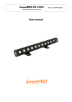
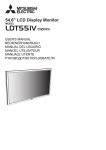
USER MANUAL
LED ENGINE XB-SD
LED Engine XB-SD Models
Model Number
Model Name
No. of
Output
Ports
For LED type
Mains Supply
PX.IC.5060100
LED Engine XB-SD 1W-216 220V
6
1W/K2-350mA
220V
PX.IC.5060200
LED Engine XB-SD 1W-216 110V
6
1W/K2-350mA
110V
PX.IC.5030100
LED Engine XB-SD 3W/K2-108 220V
3
K2-700mA
220V
PX.IC.5030200
LED Engine XB-SD 3W/K2-108 110V
3
K2-700mA
110V
PX.ID.5120100
LED Engine XB-SD Rackmount 1W/K2-432 220V
12
1W/K2-350mA
220V
PX.ID.5120200
LED Engine XB-SD Rackmount 1W/K2-432 110V
12
1W/K2-350mA
110V
PX.ID.5060100
LED Engine XB-SD Rackmount 3W/K2-216 220V
6
K2-700mA
220V
PX.ID.5060200
LED Engine XB-SD Rackmount 3W/K2-216 110V
6
K2-700mA
110V
2
System components
1.
2.
3.
4.
5.
6.
LCD display with Backlight timing option
10 push buttons
DMX-512 input and output 3 pin XLR connectors
DMX-512 addressing
Operating voltage 115v / 230v
5 modes of operation
a. DMX-512 control:
i. Control of up to 36 channels (12 RGB outputs).
b. Chaser mode:
i. Up to 9 chasers. Each chaser made of up to 32 steps with custom
fade and delay timing options.
c. Macro mode:
i. Turns the LED Engine XB-SD panel into quick chaser selection
keypad.
d. FX Mode:
i. Create astonishing wave effects.
e. Master Transmitter mode:
i. Transmits at the DMX line all current channels levels.
7. Extra Features
a. Channels doubling:
i. You can limit the maximum number of control channels
from 1 to 36 .
b. Master Dim:
i. You can enable the Master Dim feature for DMX Mode if
you wish to control the master level of all the outputs.
Getting started
Connect your LED system/s to LED Engine XB-SD. Connect LED Engine XB-SD to
the mains; LED Engine XB-SD will start at the last state it was turned off at (only if the
last state was Chaser, Macro, FX, Manual, or DMX).
Choose relevant MODE by pressing button #5.
R1
00
G1
00
B1
00
MODE
MANUAL
1
2
3
4
5
6
7
8
9
10
*Note: In case you get a "Buttons Locked" message on LCD screen when you press
one of the buttons, the LED Engine XB-SD is in Button Lock mode. To unlock the
buttons press and hold the #1 and #5 keys simultaneously until you get a message:
"Buttons Unlocked".
Remember: The buttons will lock up again as soon as LCD backlight goes off. You
can disable the auto buttons locking in the System Utilities menu.
3
Manual MODE
R1
00
G1
00
B1
00
MODE
MANUAL
1
2
3
4
5
6
7
8
9
10
Each output which consists of three channels (R-G-B by default) is represented by a
color group. For example: output #1 (channels 1-3) is represented by color group #1,
which is shown as R1 G1 B1 (see figure above). The letter represents a color (R for
red, G for green, B for blue) and the digit next to the letter represents a number of a
color group.
Button #1 / #6 – Value up / down
Button #2 / #3 – Scroll Between the colors (RGB) in current color group
Button #7 / #8 – Scroll Between the color groups RGB1 to RGB6
When you press two buttons - #1 & #6 simultaneously the level will change from zero
to full and from full to zero at instance.
To copy previous color group over the current one instantly press button #10.
FX MODE
MODE FX
Macro
FX: 1
1
2
3
4
5
6
7
8
9
10
This mode allows you to create astonishing visual effects of running wave that will
spread among the 18 ( channels of the LED Engine XB-SD.
4
By changing its eight parameters you can create various wave effects.
You can choose between 9 different presets by pressing buttons #4 and #9.
To select a desired preset press button #10. You can now modify the preset's settings
as follows:
Frq
55
Spd
80
Sft
0
MODE
FX
1
2
3
4
5
6
7
8
9
10
To access other features of the FX MODE hold button #4 for the Amplitude and Offset
Settings or hold button #9 for the RGB master level settings.
Ampl
55%
Offst
80
MODE
FX
Red
55%
Grn Blu
80% 0%
MODE
FX
1
2
3
4
5
1
2
3
4
5
6
7
8
9
10
6
7
8
9
10
While holding those buttons press corresponding buttons to change desirable feature.
For example while holding button #4, press buttons #1 / #6 to change The Amplitude.
Explanation of abbreviations:
• Frq: - (changed by the #1 / #6 buttons).
The frequency of the wave i.e. number of wave cycles within the range of the
channels. Values range 1-127 – the wave runs in direction from first to 18's
channel, 128-255 – the wave runs in direction from 18's to first channel (2).
Examples:
Level
Level
100%
100%
50%
50%
Channel
0%
1
9
18
Frequency value of 25
0%
1
9
Channel
18
Frequency value of 45
5
Spd: - (changed by the #2 / #7 buttons).
The speed of the running wave. The higher the value – the faster wave runs.
Sft: - (changed by the #3 / #8 buttons).
The color shift of the wave. You can create an offset between the color inside the
wave – thus splitting the wave into 3 different waves – wave of Red color, Green
and Blue colors. The higher the number the bigger shift between the waves. Value
of 0 – no shift.
Ampl: - (changed by the #1 / #6 buttons while holding button #4).
The amplitude (magnitude) of the wave i.e. the height of a waveform above or
below its zero baseline. You can change the magnitude of the wave from 0% - zero
fluctuation, to 200% - twice the normal fluctuation.
•
•
•
Examples:
Level
Level
100%
100%
50%
50%
Channel
0%
9
1
Channel
0%
1
18
Amplitude value of 100%
9
18
Amplitude value of 50%
Offst: - (changed by the #2 / #7 buttons while holding button #4).
The output level offset of the wave i.e. the value of the wave baseline.
When set to 0 – the baseline is on 50% of the output level. You can change the
offset from -100 to +100.
•
Examples:
Level
Level
100%
100%
50%
50%
Channel
0%
Channel
0%
1
18
9
1
9
Offset value of 0
•
18
Offset value of -30
Red/Grn/Blu: - (changed by the #1 / #6, #2 / #7, #3 / #8 buttons respectively while
holding button #9).
The RGB master level settings. You can control the master volume of each color of
the wave with this feature.
*Note: When LCD backlight turns off, a visual representation of the first 16 channels
will appear on the screen:
1
2
3
4
5
6
7
8
9
10
6
This screen also will appear if you hold the button #10. You can also change all of the
parameters described above while holding button #10 so you'll see a visual
representation of how the changes affect the wave.
For example by pressing buttons #1 / #6 while holding button #10 you can literally see
the frequency changes of the wave, by pressing buttons #1 / #6 while holding buttons
#10 and #4 you can see the changes in the amplitude of the wave.
Chaser / Macro MODE
The display will show: MODE CHASER: #
By pressing buttons #4 & #9 you may choose the relevant CHASER
(Total 9 Chasers).
MODE CHASER
Macro Edit 1
MODE CHASER
Macro Edit 2
1
2
3
4
5
1
2
3
4
5
6
7
8
9
10
6
7
8
9
10
Editing a Chaser:
Once in CHASER mode, press button 3, the display will show the CHASER editing
interface:
R2
06
G2
03
B2
26
CHS:01
St 03
1
2
3
4
5
6
7
8
9
10
Current Chaser number
Current Step number
Changing the channel values is done the same way as in MANUAL mode:
Button #1 / #6 – Value up / down
Button #2 / #3 – Scroll Between the colors (RGB) in current color group
Button #7 / #8 – Scroll Between the color groups RGB1 to RGB6
Button #4 / #9 – Scroll Between steps
To reset all color groups in current step, instantly press both buttons #6 & #10,
simultaneously.
To reset a CHASER, press and hold buttons #6 & #10, simultaneously, for about 3
seconds until “Chaser Cleared!” is displayed.
When you press two buttons - #1 & #6 simultaneously the level will change from zero
to full and from full to zero at instance.
7
To copy previous color group over the current one instantly press button 10.
To copy values of all channels from previous step over the current one press and hold
button 10 for about 3 seconds.
In order to return to chaser main menu press button 5. If changes were made to the
chaser, the following screen will appear:
Save
YES
CHANGES?
NO
1
2
3
4
5
6
7
8
9
10
Press button #1 if you want to save the
changes or button #5 do discard the changes
you made to the current chaser.
Running Chaser
Select the relevant CHASER by pressing buttons #4 & #9 and press button 10 to run
the selected CHASER
MODE CHASER
Macro Edit 1
MODE CHASER
Macro Edit 2
1
2
3
4
5
1
2
3
4
5
6
7
8
9
10
6
7
8
9
10
Fade
0.2
Wait
1.2
St
01
CHS
3 >
1
2
3
4
5
6
7
8
9
10
Explanation of abbreviations:
• Fade: - (changed by the #1 / #6 buttons).
The fade time for each step. You can change the fade time in steps of 0.2s
• Wait: - (changed by the #2 / #7 buttons).
The delay time after each step before fading to a new one. You can change wait
time in steps of 0.2 second.
8
•
ST: - (changed by the #4 / #9 buttons).
The step number in currently running chaser.
The ">" sign in the lower right corner means that the chase is "Running". If you
press buttons #4 / #9 during chase run, it will enter "pause" mode
(the " sign will show instead of ">") later you can select desirable step with
#4 / #9 buttons. To resume running the chaser press button #10
CHS: - is a current chaser number.
•
.
To return to previous mode, press button #5.
*Note: When LCD backlight turns off, a visual representation of the first 16 channels
will appear on the screen:
Press any button to get back.
1
2
3
4
5
6
7
8
9
10
This screen also will appear if you hold the button #10. You can also change all of the
parameters described above while holding button #10 so you'll see a visual
representation of how the changes affect the steps.
For example by pressing buttons #1 / #6 while holding button #10 you can literally see
how the changes in Fade affect the fade time for each step.
Macro MODE
Macro MODE is a mode that turns your LED Engine XB-SD keypad into a Macro
keypad where each button represents corresponding chaser from 1 to 9.
To enter Macro MODE press button #1 from the Chaser MODE:
MODE CHASER
Macro
Edit 1
1
2
3
4
5
6
7
8
9
10
LED Engine XB-SD will run the first chaser. If you wish to select a different chaser, just
press its corresponding button - button #1 for chaser 1, button #2 for chaser 2 and so
on…
9
If you want to get back to Chaser MODE press buttons #1 and #10 together:
MACRO MODE
Running Chase:
1
1
2
3
4
5
6
7
8
9
10
DMX-512 MODE
Press button #5, until the display shows as below
DMX MODE
Addr: 1
1
2
3
4
5
6
7
8
9
10
The DMX Address of LED Engine XB-SD is changeable in the System Utilities Menu.
In order LED Engine XB-SD controller to be able to receive DMX-512,
the COMM MODE should be set to Slave.
*Note: if the DMX signal is lost, LED Engine XB-SD will retain the last values received.
If you want to control the master level of all outputs via external DMX-512 console
then the Master Dim setting should be set to ON on all the LED Engine XB-SD
units in the chain.
*Note: if the master level is set to 0 value while Master Dim is ON then the values of
all the outputs will be 0.
The number of channels (No. Channels) setting that is set on the LED Engine XBSD also affects the way that channels are controlled. For example:
If No. Channels setting is set to 3, then the unit will occupy only 3 DMX channels.
*Note: if the Master Dim is ON then LED Engine XB-SD will also occupate an
additional channel for the master fader.
10
If there is no need for using external DMX-512 input and you want a number of LED
Engine XB-SD controllers to operate in synchronization with another LED Engine XBSD (we shall call it MASTER LED Engine XB-SD), then the COMM MODE of
MASTER LED Engine XB-SD in the chain should be set to Master.
*Note: in this case Master Dim should be disabled and the No. Channels should be
the set to the same value on all of the units including the MASTER LED Engine XB-SD.
DMX-512 Auto-addressing MODE
The DMX-512 Auto-addressing MODE allows easy chaining of LED Engine XB-SD
controllers without manually assigning each controller its own DMX address.
In this mode each LED Engine XB-SD in the chain occupies a number of channels as
set in No. Channels setting , and each LED Engine XB-SD that is connected next in
chain will be automatically assigned a DMX address that comes next in order.
To enter the DMX-512 Auto-addressing MODE you must first set the
Autoaddressing setting to ON in the System Utilities Menu, then press button #5
until the display shows as below
ADMX MODE
Addr: 1
1
2
3
4
5
6
7
8
9
10
*Note: when the Autoaddressing setting is ON the DMX MODE will be replaced with
ADMX MODE.
LED Engine XB-SD System Utilities
To enter System Utilities Menu:
Press button #5 until LED Engine XB-SD is in MANUAL MODE
R1
00
G1
00
B1
00
MODE
MANUAL
1
2
3
4
5
6
7
8
9
10
11
Press and hold button #10 for about 3 seconds, until the display is presented as below:
Back Light: 255
Change
Menu
1
2
3
4
5
6
7
8
9
10
Press button #4 or #9 to scroll between the options
Press button #1 or #6 to change the value.
The available options are:
1. Back Light – set the backlight time out in seconds
2. DMX Address – set DMX starting address for a DMX mode
3. COMM MODE: Master/Slave – If set to Master: LED Engine XB-SD switches
its DMX port to Output and operates as a DMX transmitter of its own Channels
at starting address – 1(Very useful when there is need for a synchronous
operation of LED Engine XB-SD Devices).
*Note: In DMX mode LED Engine XB-SD operates as usual
-If set to Slave: LED Engine XB-SD never operates as transmitter.
4. Reset All Memory
-If you want to clear all the settings and chasers to defaults, press and hold
button #6 for about 5 seconds until unit reboots.
5. Buttons Lock: ON/OFF
– If set to ON the buttons will automatically lock up whenever the LCD backlight
goes off.
To unlock the buttons press and hold the 1 and 5 keys simultaneously until you get
a message: "Buttons Unlocked".
*Note: If LED Engine XB-SD was turned off while its buttons were locked – they
will be initially locked upon powering up next time.
-If set to OFF: Buttons will never lock up.
6. Master Dim
-You can enable the Master Dim feature for DMX Mode if you wish to control
the master level of all the outputs.
7. No. Channels
- You can limit the maximum number of control channels from 1 to 18 . For
example if number of working channels set to 9 channel mode - outputs 10-18
will be a copy of 1-9. If number of working channels set to 3 - outputs 4-6, 7-9,
10-12, 13-15, 16-18 will be a copy of 1-3.
8. Autoaddressing: ON/OFF
-Enables / disables the Auto-addressing function.
To save the changes, just go back to MANUAL MODE by pressing button #5
12
LED Engine XB-SD – Express users guide
Buttons Unlocking
1■&5■ –3 sec press
Mode Manual
5■–Mode Manual
1▲– 6▼– Change Value
2◄– 3►– Scroll between colors in the RGB group
7◄– 8►– Scroll between RGB groups (1-6)
10■ – Copy values from previous group to current color group
10■ – 3 sec press – enter system utilities
System utilities
4▲– 9▼– Scroll between options
1▲– 6▼– Change current option's value
5■ – Go back to Manual Mode
Mode FX
No button hold
1▲– 6▼– Change wave frequency
2▲– 7▼– Change wave speed
3▲– 8▼– Change Shift between colors
4■ – Hold to enable:
1▲– 6▼– Change wave Amplitude
2▲– 7▼– Change wave offset
9■ – Hold to enable:
1▲– 6▼– Change master RED
2▲– 7▼– Change master GREEN
3▲– 8▼– Change master BLUE
10■ – Hold to preview the outputs on the LCD display
Mode Chaser
4▲– 9▼– Select Chaser
3■ – Edit Chaser
1▲– 6▼– Change Value
2◄– 3►– Scroll between colors in the RGB group
7◄– 8►– Scroll between RGB groups (1-6)
4▲– 9▼– Scroll between Steps
10■ – Copy values from previous group to current color group
10■ – (3 sec press) - copy all the values from previous step
6■&10■ – (3 sec press) - Erase Chaser
5■ – Return to Select Chaser Mode
1■ – Enter Macro Mode
1▲ to 9▼– Run chaser that corresponds to button number
1■&10■ – Return to Select Chaser Mode
10■ – Run Chaser
1▲– 6▼– Fade Time
3▲– 8▼– Wait Time
4▲– 9▼– Stop
4▲– 9▼– Select Step
10■ – Run Chaser
5■ – Return to Select Chaser Mode
Mode DMX
■–Receive DMX
13
Please check for the latest updates and changes on the TRAXON website.
© 2008, 2009 TRAXON TECHNOLOGIES ALL RIGHTS RESERVED.
WWW.TRAXONTECHNOLOGIES.COM
10/09 V0.3