1
MPC8568E MDS Processor Board
User’s Guide
Rev. 0.3
06/2007
MPC8568E MDS Processor Board, Rev. 0.3
Freescale Semiconductor
Chapter 1
General Information
1.1
Introduction. . . . . . . . . . . . . . . . . . . . . . . . . . . . . . . . . . . . . . . . . . . . . . . . . . . . . . . . . . . . . . . . .
1.2
Working Configurations . . . . . . . . . . . . . . . . . . . . . . . . . . . . . . . . . . . . . . . . . . . . . . . . . . . . . . .
1.2.1
Stand-Alone Mode (host) . . . . . . . . . . . . . . . . . . . . . . . . . . . . . . . . . . . . . . . . . . . . . . . . . . .
1.2.2
PIB Combined Mode (host or agent) . . . . . . . . . . . . . . . . . . . . . . . . . . . . . . . . . . . . . . . . . .
1.2.3
With PCI-express and/or sRIO (host or agent) . . . . . . . . . . . . . . . . . . . . . . . . . . . . . . . . . . .
1.2.4
As an agent in a PC. . . . . . . . . . . . . . . . . . . . . . . . . . . . . . . . . . . . . . . . . . . . . . . . . . . . . . . .
1.3
MPC8568E MDS Processor Board. . . . . . . . . . . . . . . . . . . . . . . . . . . . . . . . . . . . . . . . . . . . . . .
1.3.1
Features . . . . . . . . . . . . . . . . . . . . . . . . . . . . . . . . . . . . . . . . . . . . . . . . . . . . . . . . . . . . . . . . .
1.3.2
External Connections . . . . . . . . . . . . . . . . . . . . . . . . . . . . . . . . . . . . . . . . . . . . . . . . . . . . . .
1.3.3
Block Diagram . . . . . . . . . . . . . . . . . . . . . . . . . . . . . . . . . . . . . . . . . . . . . . . . . . . . . . . . . . .
1.4
Definitions, Acronyms, and Abbreviations . . . . . . . . . . . . . . . . . . . . . . . . . . . . . . . . . . . . . . . .
1.5
Related Documentation. . . . . . . . . . . . . . . . . . . . . . . . . . . . . . . . . . . . . . . . . . . . . . . . . . . . . . . .
1.6
Specifications . . . . . . . . . . . . . . . . . . . . . . . . . . . . . . . . . . . . . . . . . . . . . . . . . . . . . . . . . . . . . . .
1-1
1-2
1-2
1-2
1-2
1-2
1-2
1-2
1-4
1-6
1-7
1-8
1-9
Chapter 2
Hardware Preparation and Installation
2.1
Unpacking Instructions . . . . . . . . . . . . . . . . . . . . . . . . . . . . . . . . . . . . . . . . . . . . . . . . . . . . . . . . 2-1
2.2
Installation Instructions. . . . . . . . . . . . . . . . . . . . . . . . . . . . . . . . . . . . . . . . . . . . . . . . . . . . . . . . 2-1
2.2.1
For Stand-Alone Mode (processor board as host) . . . . . . . . . . . . . . . . . . . . . . . . . . . . . . . . 2-1
2.2.2
For PIB Combined Mode . . . . . . . . . . . . . . . . . . . . . . . . . . . . . . . . . . . . . . . . . . . . . . . . . . . 2-3
2.2.2.1
Processor Board as Host on PIB . . . . . . . . . . . . . . . . . . . . . . . . . . . . . . . . . . . . . . . . . . . 2-3
2.2.2.2
Processor Board as an agent on the PIB . . . . . . . . . . . . . . . . . . . . . . . . . . . . . . . . . . . . . 2-9
2.2.3
For PCI-express . . . . . . . . . . . . . . . . . . . . . . . . . . . . . . . . . . . . . . . . . . . . . . . . . . . . . . . . . 2-13
2.2.4
For sRIO . . . . . . . . . . . . . . . . . . . . . . . . . . . . . . . . . . . . . . . . . . . . . . . . . . . . . . . . . . . . . . . 2-18
2.2.5
In a PC . . . . . . . . . . . . . . . . . . . . . . . . . . . . . . . . . . . . . . . . . . . . . . . . . . . . . . . . . . . . . . . . 2-20
Chapter 3
Memory Map
3.1
MPC8568E MDS Processor Board Mapping . . . . . . . . . . . . . . . . . . . . . . . . . . . . . . . . . . . . . . . 3-1
Chapter 4
Controls and Indicators
4.1
4.2
4.3
4.4
4.4.1
DIP Switches. . . . . . . . . . . . . . . . . . . . . . . . . . . . . . . . . . . . . . . . . . . . . . . . . . . . . . . . . . . . . . . .
Jumpers . . . . . . . . . . . . . . . . . . . . . . . . . . . . . . . . . . . . . . . . . . . . . . . . . . . . . . . . . . . . . . . . . . . .
LEDs . . . . . . . . . . . . . . . . . . . . . . . . . . . . . . . . . . . . . . . . . . . . . . . . . . . . . . . . . . . . . . . . . . . . . .
Other Controls and Indicators. . . . . . . . . . . . . . . . . . . . . . . . . . . . . . . . . . . . . . . . . . . . . . . . . . .
Push Buttons . . . . . . . . . . . . . . . . . . . . . . . . . . . . . . . . . . . . . . . . . . . . . . . . . . . . . . . . . . . . .
4-1
4-6
4-7
4-9
4-9
MPC8568E MDS Processor Board, Rev. 0.3
Freescale Semiconductor
i
Chapter 5
Functional Description
5.1
5.1.1
5.1.2
5.1.3
5.1.4
5.1.5
5.1.6
5.1.7
5.2
5.3
5.4
5.4.1
5.4.2
5.4.3
5.4.4
5.4.5
5.4.6
5.4.7
5.4.8
5.4.9
5.4.10
5.4.11
5.4.12
5.4.13
5.4.14
5.4.15
5.5
5.5.1
5.5.2
5.5.3
5.5.4
5.5.5
5.5.6
5.5.7
5.5.8
5.5.9
5.6
5.6.1
5.6.2
5.6.3
5.7
5.7.1
Reset & Reset - Configuration . . . . . . . . . . . . . . . . . . . . . . . . . . . . . . . . . . . . . . . . . . . . . . . . . . 5-1
Reset Clocking and Configuration Initialization . . . . . . . . . . . . . . . . . . . . . . . . . . . . . . . . . 5-1
Reset Circuit . . . . . . . . . . . . . . . . . . . . . . . . . . . . . . . . . . . . . . . . . . . . . . . . . . . . . . . . . . . . . 5-3
MPC8568E MDS Processor Board Reset Principles . . . . . . . . . . . . . . . . . . . . . . . . . . . . . . 5-4
Power-On Reset . . . . . . . . . . . . . . . . . . . . . . . . . . . . . . . . . . . . . . . . . . . . . . . . . . . . . . . . . . 5-4
Hard Reset. . . . . . . . . . . . . . . . . . . . . . . . . . . . . . . . . . . . . . . . . . . . . . . . . . . . . . . . . . . . . . . 5-4
COP/JTAG Port Hard - Reset (stand-alone only). . . . . . . . . . . . . . . . . . . . . . . . . . . . . . . . . 5-4
Soft Reset . . . . . . . . . . . . . . . . . . . . . . . . . . . . . . . . . . . . . . . . . . . . . . . . . . . . . . . . . . . . . . . 5-5
Default Settings. . . . . . . . . . . . . . . . . . . . . . . . . . . . . . . . . . . . . . . . . . . . . . . . . . . . . . . . . . . . . . 5-5
Clocking . . . . . . . . . . . . . . . . . . . . . . . . . . . . . . . . . . . . . . . . . . . . . . . . . . . . . . . . . . . . . . . . . . . 5-5
Board Control & Status Registers (BCSR) - CPLD device . . . . . . . . . . . . . . . . . . . . . . . . . . . . 5-7
Programming the BCSRs via the Ethernet port, Ethernet Tap, or Serial port . . . . . . . . . . . 5-8
Programming the BCSRs via the USB Tap . . . . . . . . . . . . . . . . . . . . . . . . . . . . . . . . . . . . . 5-8
BCSR0 - Board Control / Status Register - 0 . . . . . . . . . . . . . . . . . . . . . . . . . . . . . . . . . . . 5-10
BCSR1 - Board Control / Status Register - 1 . . . . . . . . . . . . . . . . . . . . . . . . . . . . . . . . . . . 5-10
BCSR2 - Board Control / Status Register - 2 . . . . . . . . . . . . . . . . . . . . . . . . . . . . . . . . . . 5-11
BCSR3- Board Control / Status Register - 3 . . . . . . . . . . . . . . . . . . . . . . . . . . . . . . . . . . . 5-11
BCSR4- Board Control / Status Register - 4 . . . . . . . . . . . . . . . . . . . . . . . . . . . . . . . . . . . 5-12
BCSR5 - Board Control / Status Register - 5 . . . . . . . . . . . . . . . . . . . . . . . . . . . . . . . . . . . 5-13
BCSR6 - Board Control / Status Register - 6 . . . . . . . . . . . . . . . . . . . . . . . . . . . . . . . . . . . 5-14
BCSR7 - Board Control / Status Register - 7 . . . . . . . . . . . . . . . . . . . . . . . . . . . . . . . . . . . 5-15
BCSR8 - Board Control / Status Register - 8 . . . . . . . . . . . . . . . . . . . . . . . . . . . . . . . . . . . 5-15
BCSR9 - Board Control / Status Register - 9 . . . . . . . . . . . . . . . . . . . . . . . . . . . . . . . . . . . 5-16
BCSR10 - Board Control / Status Register - 10 . . . . . . . . . . . . . . . . . . . . . . . . . . . . . . . . . 5-17
BCSR11 - Board Control / Status Register - 11 . . . . . . . . . . . . . . . . . . . . . . . . . . . . . . . . . 5-17
BCSR14 - Board Control / Status Register - 14 . . . . . . . . . . . . . . . . . . . . . . . . . . . . . . . . . 5-19
External Connections . . . . . . . . . . . . . . . . . . . . . . . . . . . . . . . . . . . . . . . . . . . . . . . . . . . . . . . . 5-20
P1 - DUART Port . . . . . . . . . . . . . . . . . . . . . . . . . . . . . . . . . . . . . . . . . . . . . . . . . . . . . . . . 5-21
P3 - SMB Connector. . . . . . . . . . . . . . . . . . . . . . . . . . . . . . . . . . . . . . . . . . . . . . . . . . . . . . 5-21
P4 - CPLD’s In-System-Programming (ISP) . . . . . . . . . . . . . . . . . . . . . . . . . . . . . . . . . . . 5-21
P5 - Debug COP Connector . . . . . . . . . . . . . . . . . . . . . . . . . . . . . . . . . . . . . . . . . . . . . . . . 5-22
P6 - PCI Express socket . . . . . . . . . . . . . . . . . . . . . . . . . . . . . . . . . . . . . . . . . . . . . . . . . . . 5-23
P7 - sRIO Connector. . . . . . . . . . . . . . . . . . . . . . . . . . . . . . . . . . . . . . . . . . . . . . . . . . . . . . 5-23
P8 - Power Connector . . . . . . . . . . . . . . . . . . . . . . . . . . . . . . . . . . . . . . . . . . . . . . . . . . . . . 5-23
P9 - Power Connector . . . . . . . . . . . . . . . . . . . . . . . . . . . . . . . . . . . . . . . . . . . . . . . . . . . . . 5-23
J3,J8,J10,J12- GETH/eTSEC Port Connectors. . . . . . . . . . . . . . . . . . . . . . . . . . . . . . . . . . 5-23
PCI . . . . . . . . . . . . . . . . . . . . . . . . . . . . . . . . . . . . . . . . . . . . . . . . . . . . . . . . . . . . . . . . . . . . . . 5-24
General . . . . . . . . . . . . . . . . . . . . . . . . . . . . . . . . . . . . . . . . . . . . . . . . . . . . . . . . . . . . . . . . 5-24
PCI Setting when MPC8568E MDS Processor Board is Host . . . . . . . . . . . . . . . . . . . . . . 5-24
PCI Setting when MPC8568E MDS Processor Board is Agent . . . . . . . . . . . . . . . . . . . . . 5-25
PCI Express (PCIe) and Serial Rapid IO (SRIO) . . . . . . . . . . . . . . . . . . . . . . . . . . . . . . . . . . . 5-25
General . . . . . . . . . . . . . . . . . . . . . . . . . . . . . . . . . . . . . . . . . . . . . . . . . . . . . . . . . . . . . . . . 5-25
MPC8568E MDS Processor Board, Rev. 0.3
ii
Freescale Semiconductor
5.7.2
5.8
5.9
5.10
5.10.1
5.10.2
5.10.3
5.11
5.11.1
5.11.2
5.11.3
5.11.4
5.11.5
5.11.6
5.11.7
5.12
5.12.1
5.12.2
5.13
5.14
5.14.1
5.14.2
5.15
5.15.1
5.15.2
5.15.3
5.15.4
5.15.5
5.15.6
5.16
5.16.1
5.16.2
5.16.3
Block Diagram . . . . . . . . . . . . . . . . . . . . . . . . . . . . . . . . . . . . . . . . . . . . . . . . . . . . . . . . . .
PCI_PCIe Adapter . . . . . . . . . . . . . . . . . . . . . . . . . . . . . . . . . . . . . . . . . . . . . . . . . . . . . . . . . .
DDR . . . . . . . . . . . . . . . . . . . . . . . . . . . . . . . . . . . . . . . . . . . . . . . . . . . . . . . . . . . . . . . . . . . . .
Local Bus . . . . . . . . . . . . . . . . . . . . . . . . . . . . . . . . . . . . . . . . . . . . . . . . . . . . . . . . . . . . . . . . .
Address Latch/ Data Transceiver . . . . . . . . . . . . . . . . . . . . . . . . . . . . . . . . . . . . . . . . . . . .
SDRAM . . . . . . . . . . . . . . . . . . . . . . . . . . . . . . . . . . . . . . . . . . . . . . . . . . . . . . . . . . . . . . .
Flash Memory . . . . . . . . . . . . . . . . . . . . . . . . . . . . . . . . . . . . . . . . . . . . . . . . . . . . . . . . . . .
GETH . . . . . . . . . . . . . . . . . . . . . . . . . . . . . . . . . . . . . . . . . . . . . . . . . . . . . . . . . . . . . . . . . . . .
GMII Interface . . . . . . . . . . . . . . . . . . . . . . . . . . . . . . . . . . . . . . . . . . . . . . . . . . . . . . . . . .
Ten Bit Interface (TBI) . . . . . . . . . . . . . . . . . . . . . . . . . . . . . . . . . . . . . . . . . . . . . . . . . . . .
Reduced Pin Count GMII (RGMII) . . . . . . . . . . . . . . . . . . . . . . . . . . . . . . . . . . . . . . . . . .
Reduced Ten Bit Interface (RTBI) . . . . . . . . . . . . . . . . . . . . . . . . . . . . . . . . . . . . . . . . . . .
MII Interface . . . . . . . . . . . . . . . . . . . . . . . . . . . . . . . . . . . . . . . . . . . . . . . . . . . . . . . . . . . .
Working with TDM, I2C, UART, SPI, UCC, UPC, and the PIB. . . . . . . . . . . . . . . . . . . .
RMII via the PIB. . . . . . . . . . . . . . . . . . . . . . . . . . . . . . . . . . . . . . . . . . . . . . . . . . . . . . . . .
Debugging Applications . . . . . . . . . . . . . . . . . . . . . . . . . . . . . . . . . . . . . . . . . . . . . . . . . . . . . .
Stand-Alone, Host/Agent on PIB, Independent Host, PCIe/sRIO Agent . . . . . . . . . . . . . .
Inserted in a PC. . . . . . . . . . . . . . . . . . . . . . . . . . . . . . . . . . . . . . . . . . . . . . . . . . . . . . . . . .
UART Ports . . . . . . . . . . . . . . . . . . . . . . . . . . . . . . . . . . . . . . . . . . . . . . . . . . . . . . . . . . . . . . .
I2C (Dual) Port . . . . . . . . . . . . . . . . . . . . . . . . . . . . . . . . . . . . . . . . . . . . . . . . . . . . . . . . . . . . .
I2C-1 . . . . . . . . . . . . . . . . . . . . . . . . . . . . . . . . . . . . . . . . . . . . . . . . . . . . . . . . . . . . . . . . . .
I2C-2 . . . . . . . . . . . . . . . . . . . . . . . . . . . . . . . . . . . . . . . . . . . . . . . . . . . . . . . . . . . . . . . . . .
External Interrupts . . . . . . . . . . . . . . . . . . . . . . . . . . . . . . . . . . . . . . . . . . . . . . . . . . . . . . . . . .
PIB Interrupt . . . . . . . . . . . . . . . . . . . . . . . . . . . . . . . . . . . . . . . . . . . . . . . . . . . . . . . . . . . .
PCI Interrupt . . . . . . . . . . . . . . . . . . . . . . . . . . . . . . . . . . . . . . . . . . . . . . . . . . . . . . . . . . . .
RTC Interrupt . . . . . . . . . . . . . . . . . . . . . . . . . . . . . . . . . . . . . . . . . . . . . . . . . . . . . . . . . . .
FLASH Interrupt. . . . . . . . . . . . . . . . . . . . . . . . . . . . . . . . . . . . . . . . . . . . . . . . . . . . . . . . .
JTAG/COP Interrupt. . . . . . . . . . . . . . . . . . . . . . . . . . . . . . . . . . . . . . . . . . . . . . . . . . . . . .
GETH Interrupt. . . . . . . . . . . . . . . . . . . . . . . . . . . . . . . . . . . . . . . . . . . . . . . . . . . . . . . . . .
Power Supply . . . . . . . . . . . . . . . . . . . . . . . . . . . . . . . . . . . . . . . . . . . . . . . . . . . . . . . . . . . . . .
Primary Power Supply . . . . . . . . . . . . . . . . . . . . . . . . . . . . . . . . . . . . . . . . . . . . . . . . . . . .
MPC8568E MDS Processor Board Power Supply Structure . . . . . . . . . . . . . . . . . . . . . . .
Power Supply Operation . . . . . . . . . . . . . . . . . . . . . . . . . . . . . . . . . . . . . . . . . . . . . . . . . . .
5-25
5-26
5-27
5-28
5-28
5-29
5-30
5-30
5-31
5-31
5-32
5-33
5-34
5-35
5-49
5-49
5-49
5-50
5-50
5-51
5-51
5-52
5-52
5-52
5-52
5-53
5-53
5-53
5-53
5-53
5-53
5-53
5-54
Chapter 6
Working with the PIB
6.1
6.2
6.3
6.4
6.4.1
6.4.2
6.5
Platform I/O Board Concept . . . . . . . . . . . . . . . . . . . . . . . . . . . . . . . . . . . . . . . . . . . . . . . . . . . .
MPC8568E MDS Processor Board as Host on PIB . . . . . . . . . . . . . . . . . . . . . . . . . . . . . . . . . .
MPC8568E MDS Processor Board as Agent on PIB . . . . . . . . . . . . . . . . . . . . . . . . . . . . . . . . .
Working with a TDM module on the PIB . . . . . . . . . . . . . . . . . . . . . . . . . . . . . . . . . . . . . . . . .
Installing the PMC-to-PMC adaptor. . . . . . . . . . . . . . . . . . . . . . . . . . . . . . . . . . . . . . . . . . .
Signals on the PMC-to-PMC adaptor . . . . . . . . . . . . . . . . . . . . . . . . . . . . . . . . . . . . . . . . . .
MPC8568E MDS Processor Board - PIB Signals . . . . . . . . . . . . . . . . . . . . . . . . . . . . . . . . . . .
6-1
6-2
6-3
6-3
6-3
6-5
6-7
MPC8568E MDS Processor Board, Rev. 0.3
Freescale Semiconductor
iii
Chapter 7
Replacing Devices
7.1
Replacing Flash Memory . . . . . . . . . . . . . . . . . . . . . . . . . . . . . . . . . . . . . . . . . . . . . . . . . . . . . .
7.1.1
Cleaning Flash Memory . . . . . . . . . . . . . . . . . . . . . . . . . . . . . . . . . . . . . . . . . . . . . . . . . . . .
7.2
Replacing SODIMM unit . . . . . . . . . . . . . . . . . . . . . . . . . . . . . . . . . . . . . . . . . . . . . . . . . . . . . .
7.3
Replacing MPC8568E Processor . . . . . . . . . . . . . . . . . . . . . . . . . . . . . . . . . . . . . . . . . . . . . . . .
7-1
7-2
7-3
7-4
MPC8568E MDS Processor Board, Rev. 0.3
iv
Freescale Semiconductor
Chapter 1
General Information
1.1
Introduction
The MPC8568E MDS Processor Board is an application development system that provides a complete
debugging environment for engineers developing applications for the MPC8568 series of Freescale
processors. This document describes the MPC8568E MDS Processor Board, and how it works in its
stand-alone operating mode, as an agent via a PCI slot in a PC, as a host on the “PowerQUICC MDS
Platform I/O Board (PIB)”, as an agent on the PIB, as an sRIO host and agent, and as a PCIe root complex
and endpoint.
The MPC8568E integrates an e500 processor core based on Power Architecture™ technology with system
logic required for networking, telecommunications, and wireless infrastructure applications. The
MPC8568E is a member of the PowerQUICC™III family of devices that combine system-level support
for industry-standard interfaces with processors that implement the Power Architecture technology.
In addition, the MPC8568E offers a double-precision floating-point auxiliary processing unit (APU), 512
Kbytes of level-2 cache, QUICC Engine, two integrated 10/100/1Gb enhanced three-speed Ethernet
controllers (eTSECs) with TCP/IP acceleration and classification capabilities, a
DDR/DDR2/FCRAM1™/FCRAM2™ SDRAM memory controller, a 32-bit PCI controller, a
programmable interrupt controller, two I2C controllers, a four-channel DMA controller, an integrated
security engine with XOR acceleration, a general-purpose I/O port, and dual universal asynchronous
receiver/transmitters (DUART). For high speed interconnect, the MPC8568E provides a set of multiplexed
pins that support two high-speed interface standards: 1x/4x serial RapidIO (with message unit), and up to
x8 PCI Express.
The MPC8568E MDS Processor Board includes various peripherals, such as data input/output devices
(GETH, DUART), memories (DDR, SDRAM, Serial EEPROM, FLASH and BCSR registers), PCI, PCI
Express, and serial RapidIO connections, in addition to control switches and LED indicators.
Using its on-board resources and debugging devices, a developer is able to upload code, run the code, set
breakpoints, display memory & registers and connect his own proprietary hardware to be incorporated into
a target system that uses the MPC8568E as a processor.
The software application developed for the MPC8568E can be run in a "bare bones" operation (with only
the MPC8568E processor), or with various input or output data streams, such as from the GETH
connection, PCI, PCIe, or sRIO connections. Results can be analyzed using the Code Warrior® debugger
in addition to using other methods for directly analyzing the input or output data stream. The BSP is built
using the Linux OS.
This board can also be used as a demonstration tool for the developer. For instance, the developer's
application software may be programmed into its Flash memory and run in exhibitions.
MPC8568E MDS Processor Board, Rev. 0.3
Freescale Semiconductor
1-1
1.2
1.2.1
Working Configurations
Stand-Alone Mode (host)
The MPC8568E MDS Processor Board can be run in a stand-alone mode, like other application
development systems, with direct connections to debuggers (via a JTAG/COP connector and
JTAG/Parallel Port command converter), power supply, and the GETH, and Dual RS-232 (DUART)
connections. In this mode, the MPC8568E MDS Processor Board acts as a Host.
1.2.2
PIB Combined Mode (host or agent)
The MPC8568E MDS Processor Board can be connected to the PIB (the Platform I/O Board), which
provides room and connections for additional modules - these are PCI compatible devices such as (but not
limited to) additional Processor Boards from the MPC8Xxx family (acting as Agents). This capability
expands the communication and interface capabilities of the MPC8568E MDS Processor Board.
Power for the MPC8568E MDS Processor Board in this case is provided via the PIB. The PIB also
provides an additional 2x4 twisted pair for QE GETH signals to be connected via the back plane (if used).
Optical signals via 2x SFP connectors for QE GETH on the front plane side of the PIB are also provided.
1.2.3
With PCI-express and/or sRIO (host or agent)
The MPC8568E MDS Processor Board can function as a host (or root complex) to an agent (or end-point)
Processor Board, connected to the PCIe socket or the sRIO socket. It is also possible to connect any
PCIe-compatible device to the PCIe socket.
1.2.4
As an agent in a PC
In this mode, the MPC8568E MDS Processor Board acts as an Agent.
Using its PCI_PCIe adaptor, the MPC8568E MDS Processor Board can be inserted into a PC. Both power
and debugging are supplied via the PCI edge of the PCI_PCIe adaptor. If the (agent) processor board is
inserted into a PC using the PCIe edge of the PCI-PCIe adaptor, an addition power cable must be connected
to the PC (see Section 2.2.5 for more details). Other external connections are the same as in the
Stand-Alone Mode.
1.3
1.3.1
•
•
•
MPC8568E MDS Processor Board
Features
Supports MPC8568E running up to 1.00 GHz at 1.1V Core voltage.
DDR 72-bit on SODIMM, at a rate up to 533MHz
PCI edge connector (via additional adaptor) interfaces with 32bit PCI bus (used when inserted in
a PC, or as an agent on the PIB).
MPC8568E MDS Processor Board, Rev. 0.3
1-2
Freescale Semiconductor
•
•
•
•
•
•
•
•
•
•
•
•
PCI-express edge connector (via additional adaptor) interfaces with x4 PCIe (used when inserted
in a PC, or as an agent on a host MPC8568E MDS Processor Board)
Two 10/100/1000Mb/sec Ethernet Phys on QE GETH ports.
Two eTSEC (from UCC1 and UCC2) ports.
Dual RS232 transceiver on one DUART port.
Local Bus interface:
— 100MHz SDRAM memory (implemented using three units), 64Mbyte size with parity.
— One 32Mbyte (expandable) Flash with 16bit port size in socket.
— Address Latch and Buffers to support slow devices on the PIB Board.
Four Hi-speed Riser Connectors to enable connection to the PIB Board.
Debug port access via dedicated 16-pin connector (COP)
One I2C port for boot EEPROM 256Kbit, Real Time Clock (RTC), core voltage potentiometer, and
SODIMM SPD EEPROM - A second I2C port is used to connect to the Board Revision Detect
256Kbyte EEPROM.
Can function in one of four configurations:
— Stand-alone.
— Host mode on PIB (PIB combined mode - development platform with Processor Board (as a
Host) and PIB connected together)
— Independent host mode (as a “root complex” for an additional processor board connected to the
PCIe socket, or to the sRIO socket)
— Agent mode (either a PCI agent in the PIB or in a PC, a PCIe end-point connected to a root
complex processor board, or as an sRIO agent connected to a host processor board)
Board Control and Status Register (BCSR) implemented in Altera CPLD.
Three power options:
— Main 5V power is fed from external power supply for stand-alone mode.
— Power from PC supply when acting as a PCI add-in card.
— Power from the PIB when PIB and Processor Boards are combined.
PCI add-in card form factor dimensions: 285mm x 106mm.
MPC8568E MDS Processor Board, Rev. 0.3
Freescale Semiconductor
1-3
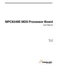
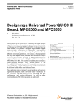
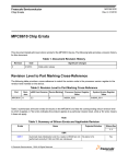
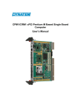
1.3.2
External Connections
The MPC8568E MDS Processor Board interconnects with external devices via the following set of
connectors:
• P1 - RJ45 (10-pin) for DUART signals
• P3 - SMB RF Connector for external pulse generator
• P4 - 16-pin header for CPLD In-System Programming (device U76)
• P5 - 16-pin COP/JTAG Connector
• P6 - PCI Express (x4) socket
• P7 - SRIO HIP Connector
• P8 - 5V Voltage Input
• P9 - 12V Voltage Input
• P12,P13,P14,P15 - 300-pin FCI Expansion Connectors.
• J3,J8 - RJ45 8-pin QE Gigabit Ethernet Connectors.
• J10,J12 - RJ45 8-pin eTSEC Connectors.
MPC8568E MDS Processor Board, Rev. 0.3
1-4
Freescale Semiconductor
Power
On/Off
P8: 5V Voltage Input
P9: 12V Voltage Input
P4: 16-pin header socket
for CPLD programming
P5: JTAG/COP
P3: SMB RF
Connector
P7: sRIO Connector
P12,P13,P14,P15:
300-pin FCI
Expansion Connectors
(on underside)
P6: PCI express x4
J3, J8: RJ45
QE Gigabit Ethernet
J10, J12: RJ45
eTSEC
(UCC1 & UCC2)
P1: RS232
Double Cable
Front Panel
Figure 1-1. MPC8568E MDS Processor Board External Connections
MPC8568E MDS Processor Board, Rev. 0.3
Freescale Semiconductor
1-5
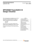
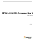
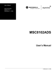
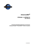
1.3.3
Block Diagram
The block diagram of the MPC8568E MDS Processor Board is shown below in Figure 1-2.
5
4
3
2
LOCAL BUS
SHEET 9
MPC8568
Riser Connector R
ADDR 52h
SHEET 17
I2C Buses
SHEET 5
I2C2
LAD[0:31]
PC18, PC19
LAD[0:31]
Address
Latch
LLA[0:31]
Riser Connector R
XLA[6:31]
133MHz
XLA[6:31]
QE
LLA[29:15]
SHEET 13
BRD EEPROM
ADDR 50h
XLA[6:30]
ADDR 2Ch
SHEET 16
ADDR 68h
I2C1
SDRAM1
32MBx16
LB
SDRAM2
32MBx16
SDRAM3
Parity
32MBx16
I2C1_SDA/SCL
FLASH
RTC
Core Voltage POT
DDR SPD EEPROM
CPLD
Altera
32MB
CS0
256Kb
ADDR XXh
XLA[27:31]
SHEET 17
ADDR XXh
ADDR 51h
Riser Connector LL
CS1,CS3
BOOT EEPROM
LAD[31:16]
XLD[15:0]
LAD[15:0]
XLD[7:0]
XLD[0:15]
LDP[0:3]
SYS & PCI CLOCK
SHEET 5
CLK
Buffer
MDS_SYSCLK
RoboCLK
Buffer
PCI_CLK1
SYSCLK
LDP[0:3]
XLGPL[0:5]
XLCS4,5
XLBCTL
XLWE0,1
XLCLK
XCTRL
PCI
Jumper
LB_CNTR
PCI1_CLK
CLK
Buffer
XPCI_CLK0,3,4,5
Ext.CLK
No_Stuff
SHMOO CLKIN FROM PIB
SHEET 17
Riser Connector R
Oscillator
Switch
PCI1_BUS
PCI1, 66MHz, 32bit
TSEC3
TSEC1
PCI Bus
SHEET 10
Giga
ETH_PHY
Addr:00010
TSEC
DDR
TSEC's
SHEET 19
BOARD CONTROL
SHEET 4
DIP-SW
TSEC4
PS
SHEET 12
1.8V/2.5V
5VIN/5V_PCI
DDR PS
GVDD
Giga
ETH_PHY
Addr:00011
TSEC2
CPLD
Jumper
3V3
DDR_SEL
#127
1->DDR2/0->DDR1
CKEN1
CKEN0
CK0~
CK0
CS1
CS0
WE
RAS
CAS
ODT1
ODT0
MCKE1
MCKE0
MCK0~
MCK0
MCS1
MCS0
MWE
MRAS
MCAS
MODT1
MODT0
MBA0:2
MBA0:2
A[0:14]
MA[0:15]
MDM[0:8]
MDM[0:8]
LVDD
2V5
PCI
PCI_REQ3,4
PCI_GNT3,4
CH.0
Switch
MDQS[0:8]
MDQS[0:8]
MECC[0:7]
MECC[0:7]
MDQ[0:63]
MDQ[0:63]
UART1
CH.1
PC[0:3]
x4
XUPC2
DDR Memory
SHEET 7
72bit SODIMM
CONFIG.
SIGNALS
RS232 PHY X2
UART0
x4
PORST
CNTR.
RS232
SHEET 5
QE
HRST
SRST
SHEET 13
SHEET 14
with ECC
HRESET
GETH1
Switch
Giga
ETH_PHY
Addr:00000
Switch
Giga
ETH_PHY
Addr:00001
PE[7:31]
SRESET
COP/JTAG
PCIe
Oscillator
GETH2
SD_REF_CLK
PF[7:31]
Switch
PI2PCIE412
LYNX
Riser Connector L
SD_TX/RX_0..3
Riser Connector RR
PD[28:31]
SD_TX/RX_4..7
SRIO
PCIe Bus
SHEET 11
Riser Connector R
Switch
SRIO x4
SHEET 17
SHEET 18
PA,PB,PC,PD
Switch
PI2PCIE412
RIO HIP Connector
SPI
Flash
4Mb
LPF
XVDD
LPF
SCORE VDD
Riser Connector LL
SHEET 15
PCIe x4
SHEET 16
x4 MB PCIe Connector
JTAG
Jumper
3V3
GETH's,
ATM,TDM
SPI
SHEET 8
TVDD
LPF
AVDD_SRDS
2V5
SENSE
5VIN/5V_PCI
CORE PS
VDD
TO ALL ON_BOARD COMPONENTS
LPF
AVDD_CE
LB
BVDD
PS
SHEET 12
LPF
AVDD_PCI1
LPF
AVDD_LBIU
LPF
AVDD_PLAT
LPF
5
4
LPF
OVDD
AVDD_CORE
CPU POWER
SHEET 6
3V3 PS
5VIN/5V_PCI
2V5 PS
2V5
1V PS
1V
3
MPC8568E-MDS
Size
C
Document Number
Date:
Tuesday, March 27, 2007
084-0
2
Figure 1-2. MPC8568E MDS Processor Board Block Diagram
MPC8568E MDS Processor Board, Rev. 0.3
1-6
Freescale Semiconductor
1.4
Definitions, Acronyms, and Abbreviations
BCSR
Board Control and Status Register
BRD
Board Revision Detect (I2C EEPROM)
BSP
Board Support Package
COP
Common On-chip Processor (JTAG Debug Port)
CPLD
A type of register
CS
Chip Select
CW
Code Warrior® IDE for PowerPC
DAC
Digital-to-Analog Converter
DDR
Double Data Rate
DIP
Dual-In-Line Package.
DMA
Direct Memory Access
DUART
Dual UART
EEPROM
Electrical Erasable Programmable Memory
FCFG
Flash Configuration Select
FCI
Type of Riser Connector
FLASH
Non volatile reprogrammable memory.
FPGA
Field-Programmable Gate Array
GbE
Gigabit Ethernet
GETH
Gigabit Ethernet
GMII
General Media Independent Interface
GPCM
General Purpose Chip-select Machine
GPL
General Purpose Line
I2C
Philips Semi Serial Bus
LBIU
Local Bus Interface Unit
LED
Light Emitting Diode
lsb
least significant bit
MDS
Modular Development System
MII
Media Independent Interface
JTAG
Joint Test Access Group
OTG
On-the-Go
PB
Processor Board
PC
IBM-compatible Personal Computer
MPC8568E MDS Processor Board, Rev. 0.3
Freescale Semiconductor
1-7
PCI
Peripheral Components Interconnect
PCIe
PCI express
Phy
Physical Layer
PIB
Platform I/O Board - expands the ADS functionality.
PLL
Phased Lock Loop
POR
Power-on reset
POS
Packet-over-SONET
PSRAM
Pseudo-Static Random Access Memory
PSU
Power Supply Unit
QE
Freescale’s QUICC-Engine chip
RCW(L,H)
Reset Configuration Word (Low/High)
RGMII
Reduced General Media Independent Interface
RTC
Real Time Clock
SDRAM
Synchronous Dynamic Random Access Memory
SMB
Type of Mini-RF connector
SODIMM
Mini DIMM Form Factor
SPD
Serial Present Detect
sRIO
Serial Rapid Input/Output
TSEC
Triple Speed Ethernet Controller
UCC
1.5
•
•
•
•
•
ULPI
UTMI+ Low Pin Interface
UPM
User Programmable Machine
USB
Universal Serial Bus
ZD
Zero Delay clock buffer, with internal PLL for skew elimination
Related Documentation
MPC8568E HW Specification
MPC8568E Reference Manual
PowerQUICC MDS Platform I/O Board User’s Manual
MPC8568E Hardware Getting Started
MPC8568E MDS Processor Board Kit Configuration Guide
MPC8568E MDS Processor Board, Rev. 0.3
1-8
Freescale Semiconductor
1.6
Specifications
The MPC8568E MDS Processor Board specifications are given in Table 1-1.
Table 1-1. MPC8568E MDS Processor Board specifications
CHARACTERISTICS
SPECIFICATIONS
Power requirements
Stand-Alone, Independent Host, or as a PCIe or sRIO
Agent (not in PC): 5V @ 8A external DC power supply
PIB Combined Mode: Power supplied by PIB
Working in PC: Power supplied by PC
MPC8568E processor
Internal clock runs at 1.00GHz @ 1.1V
Memory: One DDR bus
512MB space 72bit wide in one SODIMM-200.
Data rate 533MHz.
Local Bus: SDRAM
64MB space 32bit wide + 4bit parity implemented in three
SDRAM parts. 100MHz clock.
Buffered Memory (Flash on socket):
32MB space 16bits wide.
BCSR on CPLD
16-registers, 8bits wide.
Expansion
Four banks with 16bit- Address bus, 16bit- Data bus
connected to riser connectors
Operating temperature
0OC - 70OC
Storage temperature
-25OC to 85OC
Relative humidity
5% to 90% (non-condensing)
Dimensions (according to PCI 64-bit Add-in-card form
factor, not including heat-sink):
Length
Width
Height
285 mm
106 mm
16 mm
MPC8568E MDS Processor Board, Rev. 0.3
Freescale Semiconductor
1-9
MPC8568E MDS Processor Board, Rev. 0.3
1-10
Freescale Semiconductor
Chapter 2
Hardware Preparation and Installation
This chapter provides unpacking instructions, hardware preparation, and installation instructions for the
MPC8568E MDS Processor Board, including all four configurations: Stand-Alone, PIB Combined Mode,
Independent Host Mode, and Agent Mode (either on the PIB, inserted in a PC, directly connected to a Host
processor board via the PCI express socket, or connected to a Host processor board via an sRIO cable).
2.1
Unpacking Instructions
NOTE
If the shipping carton is damaged upon receipt, request carrier’s agent to be
present during unpacking and inspection of equipment.
CAUTION
AVOID TOUCHING AREAS OF INTEGRATED
CIRCUITRY;
STATIC
DISCHARGE
CAN
DAMAGE CIRCUITS.
1. Unpack equipment from shipping carton.
2. Refer to packing list and verify that all items are present.
3. Save packing material for storing and reshipping of equipment.
2.2
Installation Instructions
Do the following in the order indicated to install the MPC8568E MDS Processor Board properly:
1. Verify that Jumpers and Switches are in default positions
(see Chapter 4, "Controls and Indicators" for a list of default positions).
2. Determine in which working configuration you will operate the MPC8568E MDS Processor
Board:
— Stand-Alone - continue from Section 2.2.1
— PIB Combined Mode, with the PIB Board - continue from Section 2.2.2
— Working with PCI-express (as a host or as an agent)- continue from Section 2.2.3
— Working with sRIO (as a “root complex” or as an “endpoint”) - continue from Section 2.2.4
— Working as an agent in a PC - continue from Section 2.2.5
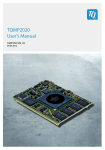
2.2.1
For Stand-Alone Mode (processor board as host)
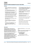
1. For Stand-Alone Mode only: Fasten the four plastic spacers. See Figure 2-1 and Figure 2-2. Note
that the smaller spacer is to be fastened to the underside of the board, as shown in the figures.
2. Connect external cables in accordance with your development needs (see Section 1.3.2 External
Connections for locations of sockets).
MPC8568E MDS Processor Board, Rev. 0.3
Freescale Semiconductor
2-1
3. Connect power supply (to 5V jack), and press the ON/OFF button (SW5), ensuring that the power
is ON.
4. Reset the board, and verify that the power-on-reset sequence is carried out properly: LD1 briefly
displays light, afterwhich LD2 and LD7 are constantly lit. (see Figure 2-3 for location). This
indicates that the board has successfully completed the boot-up sequence.
5. Continue operation according to instructions in the Kit Configuration Guide.
Large plastic spacer
(or screw)
Small plastic Spacer
Plastic Spacer - smaller spacer
on underside of board
Figure 2-1. Fastening the plastic spacers
Figure 2-2. Plastic spacers fastened
LD1 LD2
LD7
5V Power
Figure 2-3. Boot-Up sequence: LD1 turns on then off, then LD2 and LD7 remain on
MPC8568E MDS Processor Board, Rev. 0.3
2-2
Freescale Semiconductor
2.2.2
2.2.2.1
For PIB Combined Mode
Processor Board as Host on PIB
1. Remove protective covers from the 300-pin connectors (P12, P13, P14, P15) on the bottom side of
the processor board (See Figure 2-4.).
2. Remove protective covers from the 300-pin connectors on the PIB board (see Figure 2-5).
Protective Covers
Remove
protective
covers by
hand
Figure 2-5. Remove Protective Covers from 300-pin
connectors on PIB
Figure 2-4. Remove Protective Covers
from 300-pin connectors on underside of
processor board (P12, P13, P14, P15)
MPC8568E MDS Processor Board, Rev. 0.3
Freescale Semiconductor
2-3
3. Fasten processor board to PIB board as shown in Figure 2-6.
4. Ensure a tight fit by pressing down on the processor board by hand only until the pins engage.
5. Tighten screws to ensure a secure fit of the processor board on the PIB.
Press down to fasten
Figure 2-6. Connect Processor board to PIB and press down manually
6. If you will be working with a back plane, and wish GETH signals to traverse either the back plane
connection, or the front plane optical connection, connect two GETH sockets on the MPC8568E
MDS Processor Board with sockets on the PIB board as shown in Figure 2-7 and Figure 2-8. The
only communication connection between boards connected to a back plane is via the GETH
signals.
Note that if you do not do this, you can still connect GETH cables directly to the Processor board’s
sockets, if they are accessible in your development configuration.
7. Connect the power supply to the voltage input as shown in Figure 2-9.
MPC8568E MDS Processor Board, Rev. 0.3
2-4
Freescale Semiconductor
Processor Board on PIB
GETH Interconnecting
Cables
GETH Interconnecting
Cable
(connected)
GETH Sockets
Figure 2-7. Connect GETH sockets on processor
board to GETH pins on PIB
Figure 2-8. Connect GETH interconnecting
cables to sockets on PIB
Power
Figure 2-9. Connecting Power input to the PIB
MPC8568E MDS Processor Board, Rev. 0.3
Freescale Semiconductor
2-5
8. If you wish to work with a module inserted in a PCI adaptor, follow the illustrations in Figure 2-11,
Figure 2-12, and Figure 2-13 to fasten up to three PCI adaptors (one shown in Figure 2-10) to the
PIB:
a) Fasten each PCI adaptor to the PIB (by hand),
b) Insert spacers between each adaptor and the PIB,
c) Tighten them using screws (provided).
Each PCI adaptor allows you to insert a PCI-compatible module, and use it as an agent, while an
MPC8568E MDS Processor Board functions as the host.
An example of inserting a module in a PCI adaptor is shown in Figure 2-19 on page 2-12. The PCI
adaptors can be inserted in the PMC1, PMC2, and/or PMC3 slots, for up to 3 PCI adaptors, if space
allows.
Fasten using PCI adaptor’s
latches as shown
Tighten by hand
Figure 2-10. PCI Adaptor
Figure 2-11. Fastening PCI adaptor to PIB
MPC8568E MDS Processor Board, Rev. 0.3
2-6
Freescale Semiconductor
Figure 2-12. Inserting spacers between PCI
adaptor and PIB
Figure 2-13. PCI adaptor fastened to PIB
9. A fully assembled PIB-Processor board combination is shown in Figure 2-14.
All external connections of the Processor board are active when the Processor board is installed on
the PIB, except the voltage input (the Processor board receives power from the PIB power input,
or the back plane only).
In Figure 2-14, one PCI adaptor and one additional module are shown installed on the PIB. The
PCI adaptor is ready to receive any PCI-compatible board, including an 8Xxx Processor board.
Using this system, these board(s) function as agents, while the Processor board already installed
functions as a host. This allows you to take advantage of the parallel processing capabilities of the
8Xxx line of products.
Modules that can be used with the MPC8568E MDS Processor Board on the PIB are:
— E1/T1 - in the PMC0 slot only
— Quad OC3 - in the PMC0 or PMC1 slot only
10. Connect external cables in accordance with your development needs.
11. Reset the board, and verify that LD1 turns on and then turns off (see Figure 2-3 on page 2-2 for
location). It should be on for only a few moments. Then verify that LD2 and LD7 are on, and stay
on. This indicates that the board has successfully undergone the boot-up sequence, and is ready for
work.
12. Continue operation according to instructions in the Kit Configuration Guide.
MPC8568E MDS Processor Board, Rev. 0.3
Freescale Semiconductor
2-7
.
Power input for “tabletop” configuration (under processor board)
PMC3 slot
Power input for
working with
a back plane
PCI adaptor in
PMC2 slot
PMC1 slot
Additional module
installed in PMC0
slot
Back plane connection
(incl GETH and voltage)
GETH twisted pair
8 x RMII connections
Figure 2-14. Fully Assembled Combined system:
PIB, Processor Board, additional module, and PCI adaptor
MPC8568E MDS Processor Board, Rev. 0.3
2-8
Freescale Semiconductor
Agent board (MPC8349)
Power Connection
Host board
(MPC8568E)
USB Tap
Figure 2-15. Fully Assembled Combined system, with MPC8568E as host,
MPC8349 board as agent, and USB Tap connected.
2.2.2.2
Processor Board as an agent on the PIB
1. Configure the agent board as follows: set SW2.4-SW2.6 (see SW2 Configuration on page 4-3) to
‘110’ (to be an agent of a PCI host only), or to ‘100’ (to be an agent of a PCI host and an sRIO
host). Reset the board for these settings to take affect.
2. Fasten the PCI_PCIe adaptor (see Figure 2-16 on page 2-10) to the underside of the MPC8568E
MDS Processor Board, as shown in Figure 2-17 on page 2-11 and Figure 2-18 on page 2-11.
3. Insert a PCI adaptor into the PIB (as shown in Figure 2-11 and Figure 2-12 on page 2-7) in the PMC
slot in which you want to install the agent board. See Figure 2-14 (above) for indications of the
PMC slot numbering.
4. Using the PCI_PCIe adaptor’s PCI edge connector, insert the Processor Board into a PCI adaptor
as shown in Figure 2-19 on page 2-12.
MPC8568E MDS Processor Board, Rev. 0.3
Freescale Semiconductor
2-9
5. Connect external cables in accordance with your development needs.
6. Reset the agent board, and verify that the power-on-reset sequence is carried out properly: LD1
briefly displays light, afterwhich LD2 and LD7 are constantly lit. (see Figure 2-3 on page 2-2 for
location). They should be on for only a few moments. This indicates that the board has successfully
completed the boot-up sequence. Note that power is supplied from the PIB.
7. Continue operation according to instructions in the Kit Configuration Guide.
PCIe edge connector
Power Supply
Socket (for use
with PCIe connector
while in a PC)
PCI edge connector
Figure 2-16. PCI_PCIe adaptor
MPC8568E MDS Processor Board, Rev. 0.3
2-10
Freescale Semiconductor
Processor Board
PCI_PCIe adaptor
Figure 2-17. Fastening the PCI_PCIe adaptor to the MPC8568E MDS Processor Board
PCI edge
connector
PCIe edge
connector
Figure 2-18. PCI adaptor attached to MPC8568E MDS Processor Board
MPC8568E MDS Processor Board, Rev. 0.3
Freescale Semiconductor
2-11
Processor board
with PCI_PCIe adaptor
PCI
edge
connector
PCI
Adaptor
PIB
Figure 2-19. Inserting processor board into a PCI adaptor on the PIB
MPC8568E MDS Processor Board, Rev. 0.3
2-12
Freescale Semiconductor
Agent Board
Host Board
PIB
Figure 2-20. An MPC8568E MDS Processor Board as an agent on the PIB, with an additional MPC8568E MDS
Processor Board as host
2.2.3
For PCI-express
An MPC8568E MDS Processor Board can function as a host of an additional PCIe agent module. This
agent module can be either a third-party device, or an MPC8568E MDS Processor Board, functioning as
a PCIe agent. Note that the PIB is not required in this case.
1. Ensure that the host board is configured as a host, which is its default configuration (see SW2
Configuration on page 4-3 for more information). See Figure 2-21 on page 2-14 for locations of
the PCIe and sRIO sockets on the processor board.
2. Insert the edge connector of the PCIe module into the PCIe socket on the host board as shown in
Figure 2-22 on page 2-15. It may be necessary to remove the front panel of certain PCIe modules
to ensure a proper fit.
MPC8568E MDS Processor Board, Rev. 0.3
Freescale Semiconductor
2-13
CAUTION
Make sure that the PCIe module is inserted in the
direction shown in Figure 2-22 (below). Inserting it in
the wrong direction can cause damage to the PCIe
module, or to the MPC8568E MDS Processor Board.
3. If the PCIe agent module requires a 12V power supply, connect a 12V power supply to the host
MPC8568E MDS Processor Board’s 12V power jack (see Figure 2-21 (below)). LD15 being lit (on
the host board) indicates that this power input is active.
PCIexpress socket
5V Power
12V Power
sRIO socket
LD15
Figure 2-21. Processor board showing PCIe and sRIO sockets
MPC8568E MDS Processor Board, Rev. 0.3
2-14
Freescale Semiconductor
Third-party PCIe
module as agent
Front panel
of PCIe module
(removed)
PCIe socket on
MPC8568E board
Figure 2-22. PCIe agent properly inserted in PCIe socket on MPC8568E MDS Processor Board
4. If working with a MPC8568E MDS Processor Board as a PCIe agent, do the following steps:
a) Configure the agent board as follows: set SW2.4-SW2.6 to ‘010’ (see SW2 Configuration on
page 4-3 for more information).
b) Fasten the PCI_PCIe adaptor to the underside of the MPC8568E MDS Processor Board, as
shown in Figure 2-17 on page 2-11 and Figure 2-18 on page 2-11.
c) Fasten the support extender to the far end of the PCI_PCIe adaptor, as shown in Figure 2-23 on
page 2-16. This provides mechanical support for the PCIe agent board. The longer support
extender should be used if the host board will also be fastened on the PIB (see Figure 2-27 on
page 2-18) at the same time as being a PCIe host.
d) Using the PCI_PCIe adaptor’s PCIe edge connector, insert the agent Processor Board into a
host Processor Board, as shown in Figure 2-25 on page 2-16. Figure 2-26 on page 2-17 shows
two boards connected. Figure 2-27 on page 2-18 shows two boards connected while the host
board is on the PIB.
e) You can, at the same time, connect an sRIO cable between the boards (see Figure 2-28 on page
2-19 and Figure 2-29 on page 2-20 for an illustration of connecting two boards via an sRIO
cable). To do this at the same time as the PCIe, set SW2.4-SW2.6 to ‘000’ on the agent board,
thus configuring it to act as an agent (endpoint) of both a PCI Express and a serial RapidIO
(sRIO) host. Reset the board for this setting to take affect.
f) Make sure that both boards have their own power supply, connected to their respective 5V
inputs.
MPC8568E MDS Processor Board, Rev. 0.3
Freescale Semiconductor
2-15
5. Connect external cables in accordance with your development needs.
6. Reset the host board, and verify that the power-on-reset sequence is carried out properly: LD1
briefly displays light, afterwhich LD2 and LD7 are constantly lit. (see Figure 2-3 on page 2-2 for
location). They should be on for only a few moments. This indicates that the board has successfully
completed the boot-up sequence.
7. Continue operation according to instructions in the Kit Configuration Guide.
Support
extender
Figure 2-23. Fastening the support extender
Support
extender
Figure 2-24. Support extender fastened
to PCI_PCIe adaptor
PCIexpress socket
Host board
Agent module
(board)
Figure 2-25. Connecting a PCIexpress agent module to the MPC8568E MDS Processor Board
MPC8568E MDS Processor Board, Rev. 0.3
2-16
Freescale Semiconductor
Agent module
(board)
Host module
(board)
Support extender
Figure 2-26. Two boards connected via the PCIe socket
(note support extender)
MPC8568E MDS Processor Board, Rev. 0.3
Freescale Semiconductor
2-17
Agent module
(board)
Host module
(board)
Support extender
(long)
PIB
Figure 2-27. Processor Board, as PCIe agent on Host Processor Board, when the Host is on the PIB
2.2.4
For sRIO
An MPC8568E MDS Processor Board can function as an sRIO host (or “root complex”) of an additional
MPC8568E MDS Processor Board, functioning as an sRIO agent (or “endpoint”). Note that the PIB is not
required in this case.
1. Ensure that the host board is configured as a host, which is its default configuration (see SW2
Configuration on page 4-3 for more information). See Figure 2-21 on page 2-14 for locations of
the PCIe and sRIO sockets on the processor board.
2. Configure the agent (or “endpoint”) board as follows: set SW2.4-SW2.6 to ‘x01’ (see SW2
Configuration on page 4-3 for more information).
3. Connect the sRIO cable to the host (or “root complex”) board (see Figure 2-28 on page 2-19), then
to the agent (or “endpoint”) board (see Figure 2-29 on page 2-20 for an illustration of two boards
connected via an sRIO cable).
MPC8568E MDS Processor Board, Rev. 0.3
2-18
Freescale Semiconductor
4. You can, at the same time, connect the sRIO agent (endpoint) board as a PCIe agent as well (to the
same host board). To do this, set SW2.4-SW2.6 to ‘000’ on the agent board, thus configuring it to
act as an agent (endpoint) of both a PCI Express and a serial RapidIO (sRIO) host, and follow
further instructions in Section Section 2.2.3 on page 2-13to make the PCIe connection.
5. Connect a power supply to the 5V input on the agent board (both boards require their own
independent power supply).
6. Operate Code Warrior® via the host board to verify that the installation was done properly. For
more information on Code Warrior®, see the Kit Configuration Guide.
7. Connect external cables in accordance with your development needs.
8. Reset the agent board, and verify that the power-on-reset sequence is carried out properly: LD1
briefly displays light, afterwhich LD2 and LD7 are constantly lit. (see Figure 2-3 for location).
They should be on for only a few moments. This indicates that the board has successfully
completed the boot-up sequence.
9. Continue operation according to instructions in the Kit Configuration Guide.
sRIO cable
sRIO socket
Figure 2-28. Connecting an sRIO agent module to the MPC8568E MDS Processor Board
MPC8568E MDS Processor Board, Rev. 0.3
Freescale Semiconductor
2-19
sRIO cable
Host Processor
Board
Agent
Processor
Board
Figure 2-29. Two processor boards conneted via the sRIO cable
2.2.5
In a PC
An MPC8568E MDS Processor Board can function as a PCI or PCIe agent, installed in a PC. In this case,
power is supplied by the PC1, and JTAG connections are carried out via the PCI or PCIe connection.
1. Configure the agent board as follows: set SW2.4-SW2.6 to ‘110’ (see SW2 Configuration on page
4-3 for more information).
2. Fasten the PCI_PCIe adaptor to the underside of the MPC8568E MDS Processor Board, as shown
in Figure 2-17 and Figure 2-18 on page 2-11.
3. Using the PCI_PCIe adaptor’s PCI edge connector, insert the Processor Board into a PC.
4. Alternatively, you can use the PCI_PCIe adaptor’s PCIe edge connector, but in this case you must
configure SW2.4-SW2.6 to ‘010’, and you must connect the power socket on the PCI_PCIe
adaptor (see Figure 2-30) to the PC’s power supply.
5. Connect external cables to the agent board in accordance with your development needs.
6. Reset the agent board for all settings to take affect.
1. If using the PCIe edge connector, a power cable must be connected to the PCI_PCIe adaptor’s power socket.
MPC8568E MDS Processor Board, Rev. 0.3
2-20
Freescale Semiconductor
7. Operate Code Warrior® via the PC to verify that the installation was done properly. For more
information on Code Warrior®, see the Kit Configuration Guide.
Figure 2-30. PCI_PCIe adaptor: power supply socket
MPC8568E MDS Processor Board, Rev. 0.3
Freescale Semiconductor
2-21
MPC8568E MDS Processor Board, Rev. 0.3
2-22
Freescale Semiconductor
Chapter 3
Memory Map
3.1
MPC8568E MDS Processor Board Mapping
The MPC8568E Memory Controller governs all access to the processor memory slaves. Consequently the
memory map may be reprogrammed according to user needs. The memory map defined in Table 3-1 is
only a recommendation. The user can choose to work with alternative memory mapping. It should be noted
that the described mode is supported by the Code Warrior® debug tool.
After performing Hard Reset, the debug host may initialize the memory controller via the JTAG/COP
connector so this allows additional access to bus addressable peripherals. The DDR2, SDRAM and
FLASH memory respond to all types of memory access - program/data and Direct Memory Access
(DMA).
Table 3-1. MPC8568-MDS-PB Memory Map with NOR Flash as boot source
ADDRESS RANGE
00000000 - 1FFFFFFF
Memory Type
Device Name
64+8 ECC
DDR2
WV3HG64M72EEU534P
D4-M by White Electronic
Designs (512 MByte)
80000000 - 9FFFFFFF
PCI
Inbound/Outbound Window (512 MByte)
32
A0000000 - BFFFFFFF
PCIe
Inbound/Outbound Window (512 MByte)
x4 lane
C0000000 DFFFFFFF
SRIO
Inbound/Outbound Window (512 MByte)
x4 lane
E0000000 - E01FFFFF
MPC8568
Internal Map
Internal Memory Register Space (2 MByte)
32
E0200000 - E03FFFFF
Reserved
For Future derivatives of MPC8568 (2 MByte)
-
E0400000 - E047FFFF
L2-SRAM
L2 - Cash (512 KByte)
E0480000 - EFFFFFFF
Empty Space
F0000000 - F3FFFFFF
SDRAM on
CS2
F4000000 - F7FFFFFF
Empty Space
F8000000 - F8007FFF
BCSR on CS1
Altera (32 KByte)
8
F8008000 - F800FFFF
CS4
PIB
8
F8010000 - F8017FFF
CS5
PIB
8
FE000000 - FFFFFFFF
Nor Flash on
CS0
S29GL256N11TFIV2O by Spansion (32 MByte)
16
20000000 - 7FFFFFFF
WV3HG2128M72EEU806
AD4-xG by White
Electronic Designs
(2GByte)
Port Size
MT48LC16M16A2BG by Micron (64 MByte)
32+4
Parity
-
MPC8568E MDS Processor Board, Rev. 0.3
Freescale Semiconductor
3-1
MPC8568E MDS Processor Board, Rev. 0.3
3-2
Freescale Semiconductor
Chapter 4
Controls and Indicators
This chapter describes controls and indicators of the MPC8568E MDS Processor Board, which includes
switches, jumpers, LEDs, and push buttons.
4.1
DIP Switches
Figure 4-1 below shows the locations of the DIP Switches. Note that when “ON”, the value of the switch
is zero.
SW1 SW2
SW3
SW4
SW5
SW9
SW6
Figure 4-1. MPC8568E MDS Processor Board Switches Locations
Descriptions of settings for the DIP switches are described below:
MPC8568E MDS Processor Board, Rev. 0.3
Freescale Semiconductor
4-1
SW1 Configuration
1 <1
3:
->0
ON
SYS PLL3
5:
CORE PLL0
6:
CORE PLL1
7:
CORE PLL2
8:
CFG_CPU_B
OOT
4
SYS PLL2
4:
7
SYS PLL1
6
2:
3
SYS PLL0
2
1:
5
8
The "On" DIP Switch position
corresponds to a signal value of
“zero”.
SW1.1-SW1.4: SYS_PLL[0:3]
Sets the ratio by which to multiply SYSCLOCK to give the platform
frequency (CCB = SYSCLOCK * SYS_PLL[0:3])
factory setting: '0110' = 400Mhz. (ratio of 6:1)
‘0000’ - 16:1
‘0010’ - 2:1
‘0011’ - 3:1
‘0100’ - 4:1
‘0101’ - 5:1
‘1000’ - 8:1
‘1001’ - 9:1
‘1010’ - 10:1
‘1100’ - 12:1
‘1101’ - 20:1
All other values reserved
SW1.5 - SW1.7: CORE PLL[0:2]
Sets the ratio by which to multiply CCB to give the e500 core frequency
(e500 Core = CCB * CORE PLL[0:2])
factory setting: '101' = 1066Mhz (ratio of 2.5:1)
‘000’ - 4:1
‘001’ - 4.5:1
‘010’ - 1:1
‘011’ - 1.5:1
‘100’ - 2:1
‘110’ - 3:1
‘111’ - 3.5: 1
SW1.8 CFG_CPU_BOOT
Enables/Disables the e500 core to boot without waiting for configuration
by an external host
factory setting: '1' = The e500 core may boot without waiting for
configuration by an external master
‘0’ - CPU boot holdoff mode. The e500 core is prevented from booting until
configured by an external master
Default setting: 01101011
MPC8568E MDS Processor Board, Rev. 0.3
4-2
Freescale Semiconductor
SW2 Configuration
1 <ROMLOC0
2:
ROMLOC1
1
3:
ROMLOC2
2
4:
Host/Agent0
3
5:
Host/Agent1
6:
Host/Agent2
6
7:
BOOTSEQ1
7
8:
CFG_SRDS_
EN
->0
ON
4
1:
5
8
SW2.1-SW2.3: ROMLOC[0:2]
Selects the Boot ROM location from one of the following locations: PCI,
DDR, SRIO,PCIe, Local bus
factory setting: '110'; Boot from Local Bus GPCM 16bit (Flash ROM)
‘000’ - PCI
‘001’ - DDR SDRAM
‘010’ - Reserved
‘011’ - Serial RapidIO (SRIO)
‘100’ - PCI Express (PCIe)
‘101’ - Local bus GPCM 8bit (Flash ROM)
‘111’ - Local bus GPCM 32bit (Flash ROM)
SW2.4-SW2.6: Host Agent PCI,PCIe,SRIO selection. [0:2]
Configures how the MPC8568E is to work: host, or agent (PCI, PCIe, or
SRIO device)
factory setting: '111'; MPC8568 acts as the host processor/root
complex.
‘000’ - MPC8568E acts as an agent (endpoint) of both a PCI Express and
a serial RapidIO host.
‘x01’ - MPC8568E acts as an agent of a serial RapidIO host.
‘010’ - MPC8568E acts as an agent of a PCI Express host
‘011’ - Reserved
‘100’ - MPC8568E acts as an agent of both a PCI and a serial RapidIO
host
‘110’ - MPC8568E acts as an agent of a PCI host.
SW2.7 Boot Sequencer
Determines if I2C addressing mode is used, thereby enabling the boot
sequencer.
factory setting: ‘1’ - Boot sequencer is disabled. No I2C ROM is
accessed.
‘0’ - Extended I2C addressing mode is used. Boot sequencer is enabled
and loads configuration information from a ROM on the I2C1 interface.
A valid ROM must be present.
SW2.8: CFG_SRDS_EN
Enables/disables the SerDes interface
factory setting: '1'; SerDes interface enabled
‘0’ - SerDes interface is disabled. When it is disabled, the Serial RapidIO
and PCI Express controllers are also disabled
Default setting: 11011111
MPC8568E MDS Processor Board, Rev. 0.3
Freescale Semiconductor
4-3
SW3.1-SW3.5: QE PLL [0:4]
Sets the ratio by which to multiply SYSCLK to give the QECLK value
(QECLK = SYSCLK * QE_PLL[0:4])
factory setting: '0_0110' = 400Mhz (ratio of 6:1)
Other possible values:
SW3 Configuration
1 <QEPLL0
2:
QEPLL1
3:
QEPLL2
2
4:
QEPLL3
3
5:
QEPLL4
6:
QE UCC Volt
6
7:
Tsec1 Width
7
8:
Tsec2 Width
->0
8
ON
1
1:
4
0_0000 - 16:1
0_1100 - 12:1
1_0111 - 23:1
0_0001 - Reserved
0_1101 - 13:1
1_1000 - 24:1
0_0010 - 2:1
0_1110 - 14:1
1_1001 - 25:1
0_0011 - 3:1
0_1111 - 15:1
1_1010 - 26:1
0_0100 - 4:1
1_0000 - 16:1
1_1011 - 27:1
0_0101 - 5:1
1_0001 - 17:1
1_1100 - 28:1
0_0111 - 7:1
1_0010 - 18:1
1_1101 - 29:1
0_1000 - 8:1
1_0011 - 19:1
1_1110 - 30:1
0_1001 - 9:1
1_0100 - 20:1
1_1111 - 31:1
0_1010 - 10:1
1_0101 - 21:1
0_1011 - 11:1
1_0110 - 22:1
5
SW3.6: QE UCC Voltage
Sets the voltage of UCC when it works with GETH
factory setting: '1' - Voltage of UCC (when working with GETH) = 3.3V
‘0’ - UCC Voltage = 2.5V
SW3.7: Tsec1 Width
Sets the eTSEC1 width
factory setting: '1' - eTSEC1 Ethernet interface operates in standard
width TBI, GMII, MII. Or if in FIFO mode, it operates as a 16-bit FIFO.
‘0’ - eTSEC1 Ethernet interface operates in reduced pin mode, either
RTBI, RGMII, RMII, or in 8-bit FIFO mode.
SW3.8: Tsec2 Width
Sets the eTSEC2 width
factory setting '1' - eTSEC2 Ethernet interface operates in standard
width TBI, GMII, MII, or 8-bit FIFO mode.
‘0’ - eTSEC2 Ethernet interface operates in reduced mode, either RTBI,
RGMII or RMII.
Default setting: 00110111
MPC8568E MDS Processor Board, Rev. 0.3
4-4
Freescale Semiconductor
SW4 Configuration
1 <1:
Tsec1 Prtc0
2:
Tsec1 Prtc1
1
3:
Tsec2 Prtc0
2
4:
Tsec2Prtc1
->0
3
ON
4
RIO SYS SIZE
6:
PCI I/O IMPD
6
7:
PCI ARBITER
7
8:
Reserv
8
5
5:
SW4.1: SW4.2 Tsec1_Prtc[0:1].
Selects the eTSEC1 protocol: MII, GMII, TBI, or FIFO
factory setting: '10' (GMII, or RGMII if configured in reduced mode)
‘00’ - Uses 16-bit FIFO protocol (or 8-bit FIFO protocol if configured in
reduced mode)
‘01’ - Uses the MII protocol (or RMII if configured in reduced mode)
‘11’ - Uses the TBI protocol (or RTBI if configured in reduced mode)
SW4.3: SW4.4 Tsec2_Prtc[0:1].
Selects the eTSEC2 protocol: MII, GMII, TBI, or FIFO
factory setting: '10' (GMII, or RGMII if configured in reduced mode)
‘00’ - Uses 8-bit FIFO protocol
‘01’ - Uses the MII protocol (or RMII if configured in reduced mode)
‘11’ - Uses the TBI protocol (or RTBI if configured in reduced mode)
SW4.5: RIO SYS SIZE
Selects system size
factory setting: '0'; Small system size up to 256 devices.
‘1’ - Large system size (up to 65,536 devices)
SW4.6 PCI I/O Impedance:
factory setting: '0'; 25 Ohm I/O impedance.
‘1’ - 42 Ohm I/O impedance
SW4.7 : PCI Arbiter.
factory setting: '1'; The on chip PCI arbiter is enabled.
‘0’ - On-chip PCI arbiter is disabled. External arbitration is required.
SW4.8 : Reserved.
factory setting: '1'; Reserved
Default setting: 10100011
SW6 Configuration
1 <-
->0
Clock0
1
2:
Clock1
2
3:
Spread0
3
4:
Spread1
4
ON
1:
SW6.1: SW6.2 PCI Express/sRIO Clock[0:1].
Sets the clock value.
factory setting: '10' = 100MHz
‘00’ - 25MHz
‘01’ - 125MHz
‘11’ - 200MHz
SW6.3: SW6.4 PCI Express/sRIO Clock Spread[0:1].
Sets the spread value.
factory setting: '11' = No spread
‘00’ - Center +/- 0.25
‘01’ - Down - 0.75
‘10’ - Down - 0.5
Default setting: 1011
MPC8568E MDS Processor Board, Rev. 0.3
Freescale Semiconductor
4-5
SW9 Configuration
1 <2F0
2:
2F1
1
3:
FS
2
4:
Test
->0
ON
3
1:
4
SW9.1: SW9.2 Skew Control [0:1].
Sets the skew of the PCI clock.
factory setting: '11' = No skew. Use this setting on host board if using any
PCI agent except the MPC8568E board
‘00’ - (-4Tu) (Tu = time unit = 0.95ns)
‘10’ - (-3Tu) use this setting on host board if using an MPC8568E board as
agent
‘01’ - (-1Tu)
SW9.3: PLL Frequency range.
Sets the PLL frequency range.
factory setting: '1' = 48MHz - 100MHz
‘0’ - 24MHz - 50MHz
SW9.4: Test.
Disables output if skew = -4Tu (Tu = “time unit” = 0.95ns).
factory setting: '0' = disable output if skew = -4Tu
‘1’ - Do not disable output, even if skew = -4Tu
This switch provides a digitally controlled delay of the PCI_CLK signal in order
to provide stable operation of the board when it is a PCI agent
Default setting: 1110
SW5 Power Switch
ON
SW5: power switch (toggle)
• power from an external 5V power supply via the P10 power jack
• combined mode: powered from +5V on PIB power supply through riser
connectors
• board plugged as a PCI or PCIe add-in card: PC or host board internal
power supply will provide 5V via PCI/PCIe edge connector
PCB
4.2
Jumpers
Figure 4-2 below shows the locations of the jumpers.
J4/5
J2
J6
J16 J17 J19 J14
Figure 4-2. MPC8568E MDS Processor Board Jumpers Locations
Descriptions of settings for the Jumpers are described below:
MPC8568E MDS Processor Board, Rev. 0.3
4-6
Freescale Semiconductor
Table 4-1. Jumper Settings
J2:
3
2
1
Selects input for CLK7: TDMC_RXCLK or UPC2_RXCLKIN
TDMC-RXCLK
• For UPC2-RXCLKIN: Connect 1-2 (default)
• For TDMC-RXCLK: Connect 3-2
PD22 (CLK7)
UPC2-RXCLKIN
J4 & J5:
Selects input for CLK16: RMII_RXCLKODD, GE125, or XUPC1_TXCLKO
(J5/J4 is a 4-pin combined Jumper, configured as shown at left)
J5
PB31(CLK16)
3
2
1
RMII_RXCLKODD
GE125
J4
XUPC1_TXCLKO
• For RMII_RXCLKODD: Connect (JP5) 2-3
• For XUPC1_TXCLKO: Connect (JP5) 1-2
• For GE125: Connect JP4 (default)
Note: GE125 is the input clock for UCC1 & UCC1 input 125Mhz clock.
J6:
3
2
1
Selects input clock for MPC8568E (onboard or external)
External clock
Input MPC8568 clock
OnBoard clock
J14:
3
2
1
Selects input for CLK8: RMII_RXCLKEVEN or UPC2_TXCLK
RMII_RXCLKEVEN
PD23 (CLK8)
UPC2_TXCLK
J16:
3
2
1
3.3V
TSEC VDD
2.5V
3.3V
QE UCC1&2 VDD
2.5V
J19:
3
2
1
4.3
• For RMII_RXCLKEVEN: Connect 2-3 (default)
• For UPC2_TXCLK: Connect 1 - 2.
Selects input voltage for TSEC_VDD (3.3V or 2.5V)
J17:
3
2
1
• For external clock: Connect 2-3
• For internal clock: Connect 1-2 (default)
• For 3.3V: Connect 2-3
• For 2.5V: Connect 1-2 (default)
Selects input power for QE UCC1&2 (MPC8568 QE GETH block) - 3.3V or
2.5V
• For 3.3V: Connect 2-3
• For 2.5V: Connect 1-2 (default)
Enables PCI clock to be routed to expansion board of the PIB
MAC_HW-CP-G-T-SO5
XUPC2_RXD9_PCICLK4
XPCI_CLK4
• For normal operation (no re-routing of PCI clock): Connect 1-2 (default)
• To route PCI clock to expansion board: Connect 2-3
LEDs
Figure 4-3 below shows the locations of the LEDs.
MPC8568E MDS Processor Board, Rev. 0.3
Freescale Semiconductor
4-7
LD1 LD2
LD3 LD4
LD6 LD7
LD5,
8,13,16
LD14
LD15
LD9,10,11,12
Figure 4-3. MPC8568E MDS Processor Board LEDs Locations
Descriptions of LED indicator meanings are described below:
No.
LD1
Name
ASLEEP
Color
Green
LD2
TRIG_OUT
Red
LD3
LD4
LD5
DDR2
DDR1
UCC1
Green
Green
Green
LD6
Power Fail
Red
LD7
LD8
Power On
UCC2
Green
Green
LD9
LD10
LD11
LD12
BCSR
BCSR
BCSR
REG-CFG
Red
Green
Amber
Red
LD13
eTSEC3
Green
LD14
LD15
LD16
Power 5V
Power 12V
eTSEC4
Amber
Green
Green
LED On
LED Off
Device in PORESET or in
Device not in PORESET or
sleep state
sleep state
Device ready after
Device not ready
PORESET
Power supplied to DDR2
No power supplied to DDR2
Power supplied to DDR1
No power supplied to DDR1
GETH connected to UCC1
GETH not active
active
Power is not properly
If board is active, power is
supplied to device
properly supplied to device
Board power is ON
Board power is OFF
GETH connected to UCC2
GETH not active
active
Connected to BCSR5 for debugging purposes
Configuration from internal
registers
GETH connected to TSEC1
active
5V input active
12V input active
GETH connected to TSEC2
active
Configuration from DIP
switches
GETH not active
5V input not active
12V input not active
GETH not active
MPC8568E MDS Processor Board, Rev. 0.3
4-8
Freescale Semiconductor
4.4
4.4.1
Other Controls and Indicators
Push Buttons
Table 4-2 below describes the functionality of the board’s push buttons (these buttons are not available
when the board is installed in a PC). See Figure 4-4 for the locations of these push buttons.
Table 4-2. The MPC8568E MDS Processor Board Push Buttons
This button is a toggle:
If the board is not powered up, pressing button
SW5 results in power being supplied to all
components on the MPC8568E MDS
Processor Board.
SW5
Power-on-Reset
PRESET
SW7
Soft Reset
SRESET
If the board is powered up, pressing button SW5
removes all power from the components on
the MPC8568E MDS Processor Board
Pressing button SW7 results in a Soft Reset for
the MPC8568E. Despite the reset, clock and
chip-select data as well as SDRAM (if
installed) contents are retained.
Pressing button SW8 results in a Hard Reset for
the MPC8568E.
SW8
Hard Reset
HRESET
MPC8568E MDS Processor Board, Rev. 0.3
Freescale Semiconductor
4-9
SW5
SW7, 8: SReset and HReset
Figure 4-4. MPC8568E MDS Processor Board Push Buttons
MPC8568E MDS Processor Board, Rev. 0.3
4-10
Freescale Semiconductor
Chapter 5
Functional Description
In this chapter the design details of various modules of the MPC8568E MDS Processor Board are
described. This includes (but is not limited to) registers, busses, and timing.
5.1
5.1.1
Reset & Reset - Configuration
Reset Clocking and Configuration Initialization
The MPC8568E samples certain configuration pins at Power-On-Reset (POR) negation. These pins can be
grouped as follows:
• POR PLL status register (PORPLLSR)
• POR boot mode status register (PORBMSR)
• POR I/O impedance status and control register (PORIMPSCR)
• POR device status register (PORDEVSR)
• POR debug mode status register (PORDBGMSR)
(see the MPC8568E Reference Manual for more details).
Figure 5-1 below shows a schematic diagram of the reset circuit, including the various signals and their
sources.
MPC8568E MDS Processor Board, Rev. 0.3
Freescale Semiconductor
5-1
MPC8568E
JTAG-COP
RCS
CPLD
BCSR
POR-Controller
CFG_Signals
COP
COP_Signals
HRESET
SRESET
HRESET
HRESET_REQ
SRESET
RTC_Reset
FLASH_RESET
Configuration DIP
Switches Array
MEM_RESET
XPCI_RESET
PCI/PCIe Adaptor
PCI Edge Connector
XRESET
PORESET
RTC
FLASH Mem.
DDRII Slot
}
To PIB
SYS_CLK
SYSCLK
Figure 5-1. Reset Circuit Block Diagram
Once the HRESET signal is negated, the MPC8568E starts to load the Reset Configuration Signals (RCS).
These signals are latched from the DIP-switches into appropriate CPLD registers (the BCSR’s).
There are two ways to drive the RCS:
• From DIP-switches via the BCSR
• Directly from the BCSR ignoring DIP-switches setting
All the RCS bits can be changed from their initial settings using either the CPLD BCSR through the local
bus or using the LLD (low level debugger). The BCSR must then drive HRESET/ PORESET to load a new
configuration word to the device. It is possible to read the value of the RCS from the BCSRs.
Figure 5-2 below shows the timing for the reset sequence.
MPC8568E MDS Processor Board, Rev. 0.3
5-2
Freescale Semiconductor
Figure 5-2. Reset Timing Diagram
5.1.2
Reset Circuit
The following are reset sources of the MPC8568E MDS Processor Board:
• Reset controller (DS1834AS from Dallas) - drives the PORESET signal during the time from main
power supply (5VDC) connection up to the point at which the 3V output voltage from the On-board
PS becomes stable (about 350mS). As soon as this occurs, the CPLD produces corresponding
HRESET/SRESET signals to the CPU.
• JTAG COP - can drive HRESET or SRESET, depending on the command given from the JTAG
device.
• Push button for HRESET and SRESET (PCI XRST signal is connected to HRESET signal)
• The BCSR ( BCSR6[7] = 0 sets PORESET)
• HRESET REQ signal from CPU could initiate HRESET/SRESET sequence from CPLD in case of
CPLD corresponding bit set to enable the procedure.
MPC8568E MDS Processor Board, Rev. 0.3
Freescale Semiconductor
5-3
5.1.3
MPC8568E MDS Processor Board Reset Principles
Upon power on:
In PCI or PCIe
Agent mode:
The device DS1834AS drives PORESET low for about 350msec to the CPLD
after the 5V and 3V voltages are stable
The BCSR performs initialization procedures, and drives the HRESET/SRESET
signals to MPC8568E, FLASH, DDR SODIMM, RTC and PIB (if connected)
When the MPC8568E MDS Processor Board configured and connected as PCI or
PCIe Agent (or “endpoint”), PORESET could be driven by Host PCI/PCIe XRST
signal.
HRESET & SRESET can be driven through JTAG COP connector, by BCSR, by RTC when it reaches its
count value, or by push buttons.
5.1.4
Power-On Reset
The Power-On reset to the MPC8568E MDS Processor Board initializes the processor’s and all on-board
components’ states after power up. A dedicated logic unit asserts MPC8568E HRESET input for a period
long enough to cover all MPC8568E voltages and clock stabilization. A HRESET may be generated
manually as well by an on-board dedicated push-button (SW8). There are no any functional differences
between Power-On and Hard Reset from the MPC8568E’s point of view. The only difference from the
MPC8568E MDS Processor Board’s point of view is that Power-On reset loads the RCS from the
DIP-switches via BCSR (default), while HRESET saves the BCSR setting from the previous session.
In addition, a power on reset for the MPC8568E can be done by toggling setting BCSR6[7] = 0.
5.1.5
Hard Reset
Hard Reset may be generated on the MPC8568E MDS Processor Board by any one of the following
sources:
• COP/JTAG Port (in Stand-Alone Mode only)
• Manual Hard Reset.
• Board Internal sources.
A Hard Reset, when generated, causes the MPC8568E to reset all its internal hardware except for PLL
logic and re-acquires the Hard Reset configuration from its current source. Since Hard Reset also resets
the refresh logic for dynamic RAMs, their content is lost as well.
5.1.6
COP/JTAG Port Hard - Reset (stand-alone only)
To provide convenient Hard Reset capability for a COP/JTAG controller, an HRESET line from
COP/JTAG port connector muxed with Manual Hard Reset in CPLD U78. The COP/JTAG controller may
directly generate a Hard Reset by asserting (low) this line and then drive it from the CPLD to the
MPC8568E.
MPC8568E MDS Processor Board, Rev. 0.3
5-4
Freescale Semiconductor
Manual Hard Reset is provided via SW8. In addition, a manual HRESET for the MPC8568E can be done
by toggling BCSR6-[7] bit in the CPLD.
5.1.7
Soft Reset
Soft Reset signal to the MPC8568E could be provide or from external JTAG/COP controller or from
On-Board SRESET push-button (OR-function realized in U78)
Manual Soft Reset is provided via SW7.
5.2
Default Settings
The default settings for the MPC8568E MDS Processor Board are as follows:
• Clock-In (primary clock) = 66Mhz
• CCB = 400Mhz
• Core Clock = 1000Mhz
• DDR Clock = 200Mhz
• QE Clock = 400Mhz
• Local Bus Clock = 100Mhz
• DDR Type = DDR2
• Boot ROM Location: LB Flash
• PCI - Host, Arbiter Enabled, Drive 25OHm
• PCI_MODE = Asynchronous Clock, >=33MHz
• PCIe - Root Complex, x4, TX/RX Lanes 0:3
• SRIO - Host, Small System Size, x4, TX/RX Lanes 4:7
• CPU Core Boot without external master waiting
• Boot Sequencer disabled (no I2C ROM asserted)
• eTSEC1/2 operates in standard TBI,RGMII,MII mode
• Lynx Clock = 100Mhz, No Spread
5.3
Clocking
A block diagram of the MPC8568E MDS Processor Board clocking external connections is shown below
in Figure 5-3.
MPC8568E clocking internal details block diagram is shown below in Figure 5-4.
There are two modes of PCI Clock operations:
• Agent
• Host
In PCI Agent mode, the MPC8568E MDS Processor Board is inserted (using the PCI_PCIe Adaptor) in
a PCI-to-PMC adaptor on the PIB or into a PC PCI Slot. In this case, the signal PCIEDGE_ON from the
MPC8568E MDS Processor Board, Rev. 0.3
Freescale Semiconductor
5-5
PCI Edge connector (3V3 PCI) turns the PCI Clock switch to receive the CLK signal from Edge connector
and provides it to the MPC8568E device.
In PCI Host mode, the edge connector is not connected. As a result, the on-board oscillator provides
SYSCLK to the PCICLK input of the MPC8568E device.
From PCI_PCIe
Adaptor
From PIB
Ext.Gen
PCIEDGE_CLK
Riser
Conn.
Right
Switch
PLL
Buffer
MPC8568E
PCI1CLK DDR-CLK
PCIEDGE_ON
Jumper
SYSCLK
PLL
Buffer
66MHz
LB-CLK
}
XPCI_CLK0
XPCI_CLK3 Riser R
XPCI_CLK5
From BCSR_CLKEN
From PIB
Clock Synthesizer
OPTIONAL_CLK
CPLD_CLK
3
Long Trace
LSYNC-IN
CLK
PLL
Buffer
6
LSYNC-OUT
RTCCLK
SYSCLK
Short Trace
Figure 5-3. Clocks - Showing External Connection Scheme
MPC8568E MDS Processor Board, Rev. 0.3
5-6
Freescale Semiconductor
Figure 5-4. Clocks - Internal Details
5.4
Board Control & Status Registers (BCSR) - CPLD device
The CPLD (device U78) contains the BCSRs, each of which is an 8-bit wide read / write register module
that controls or monitors various MPC8568E MDS Processor Board operations. The BCSRs are accessed
from the Local Bus. The BCSR includes up to 16 registers, but only those registers in use are listed here.
The board control & status registers are duplicated up to 32 times within a CS1 region. This is due to the
CS region’s 32KB minimum block size and the fact that only address lines A[27-31] are decoded for
register selection by the BCSR. The BCSRs are implemented on a Altera CPLD device that provides
register and logic functions for some of the MPC8568E MDS Processor Board signals.
The BCSR controls or monitors the following functions:
• Power-on-Reset & Hardware configuration setting for the processor.
• Storage for Hardware Reset Configuration bits (available from the Local Bus)
• Hardware Configuration for both GETH transceivers for QE and eTSEC.
• Enable/Disable to:
— Two GETH1,2 and two eTSEC1,2 Transceivers.
— Dual RS232 Transceiver.
• Hardware write protection for FLASH and BRD I2C EEPROM .
MPC8568E MDS Processor Board, Rev. 0.3
Freescale Semiconductor
5-7
•
•
•
5.4.1
Control for software signaling (via three LEDs).
Status indications, including:
— PCI Host Mode, which indicates if the Board is working in a Host Mode (Stand-Alone,
Independent Host, or PIB Combined) or an Agent (or “endpoint”) Mode
BCSR Revision code BCSR14[0-3] REV BCSR14[4-7] SUBREV
Programming the BCSRs via the Ethernet port, Ethernet Tap, or
Serial port
The BCSRs can be reprogrammed using either the Ethernet Tap, the Ethernet port, the Serial port, or the
USB Tap. For instructions on how to do this via the Ethernet Tap, Ethernet port, or Serial port, see the
CodeWarrior online Help (enter “Reprogramming Firmware” from the Search option). Instructions on
reprogramming the BCSRs using the USB Tap are found below.
5.4.2
Programming the BCSRs via the USB Tap
Programming the BCSRs using the USB Tap is done as follows:
1. Insert the interconnection header into the 16-pin header socket for firmware programming (P4)
(see Figure 5-5 and Figure 5-6 on page 5-9 for photos of the header and how to insert it, and see
Figure 5-7 on page 5-20 for a general view).
2. Connect the USB Tap to the header.
3. Turn off power to the board, then turn on power.
4. Launch CCS and open the CCS command window. The procedure is slightly different on Windows
and Linux host machines.
— For Windows:
Run the command:
<CodeWarrior Installation>\ccs\bin\ccs.exe
This will launch CCS and add a CCS icon (
) to your taskbar. Double-click that icon in the
taskbar to open the command window.
— For Linux
Run the command:
<CodeWarrior Installation>/ccs/bin/ccs
This will launch CCS and open the command window automatically.
5. In the CCS Command window, do the following:
a) Initialize the USB Tap by typing (from the root directory):
– ccs> delete all
– ccs> config cc utap
b) Move to the BCSR directory, then type:
– ccs> cd <path>
– ccs> ::svf::burn bcsr.svf
MPC8568E MDS Processor Board, Rev. 0.3
5-8
Freescale Semiconductor
c) At this point, the program should be loaded, and you should see output similar to the following:
– "0: USB TAP (JTAG) (utap:01001762) Loader software ver. {1.8}"
– "Sending code to USB TAP - please wait"
– "Wait for a few min"
d) Wait for a few minutes, and the BCSR will then be reprogrammed.
e) Before disconnecting your USB TAP, wait for the flashing status light to turn off.
P4
socket
Figure 5-5. Interconnection header
Figure 5-6. Inserting interconnection header
MPC8568E MDS Processor Board, Rev. 0.3
Freescale Semiconductor
5-9
5.4.3
BCSR0 - Board Control / Status Register - 0
Table 5-1. BCSR0 Register Description
Bit #
Config Signals
Function
Default
Att.
[0:3]
CFG_SYS_PLL[0:3]
Establishes the clock ratio between the SYSCLK and the
platform clock (CCB)
(See See “SW1 Configuration” on page 4-2. for a list of
possible values)
SW1/[1:4]
Sampled at
HRESET
[0110]
R,W
[4:6]
CFG_CORE_PLL[0:2]
Sets the ratio between the e500 Core PLL Clock and the
platform clock (CCB)
(See See “SW1 Configuration” on page 4-2. for a list of
possible values)
SW1/[5:7]
Sampled at
HRESET
[101]
R,W
[7]
CFG_BOOT_SEQ[1]
Allows the boot sequencer to load boot configuration data
located on the I2C Boot ROM.
‘1’ - Boot sequencer is disabled. No I2C ROM is
accessed.
‘0’ - Extended I2C addressing mode is used. Boot
sequencer is enabled and loads configuration
information from a ROM on the I2C1 interface. A
valid ROM must be present.
SW2/[7]
Sampled at
HRESET
[1]
R,W
5.4.4
BCSR1 - Board Control / Status Register - 1
Table 5-2. BCSR1 Register Description
Bit #
Config Signals
Function
Default
Att.
[0:2]
CFG_ROM_LOC[0:2]
Defines from were to load the boot program. Default boot
ROM address range of 8MB at address:
0x0_FF80_0000 to 0x0_FFFF_FFFF.
(See See “SW2 Configuration” on page 4-3. for a list of
possible values)
SW2/[1:3]
Sampled at
HRESET
[110]
R,W
[3:5]
CFG_HOST_AGT[0:2]
Selects the MPC8568 SRIO/PCI/PCIe Host or agent
mode.
(See See “SW2 Configuration” on page 4-3. for a list of
possible values)
SW2/[4:6]
Sampled at
HRESET
[111]
R,W
[6]
CFG_PCI1_IMPD
Defines PCI I/O Impedance configuration
‘0’ - 25 Ohm I/O impedance.
‘1’ - 42 Ohm I/O impedance
SW4/[6]
Sampled at
HRESET
[0]
R,W
[7]
CFG_RIO_SYS_SYZE
Defines Large or small SRIO system size
'0' - Small system size up to 256 devices.
‘1’ - Large system size (up to 65,536 devices)
SW4/[5]
Sampled at
HRESET
[0]
R,W
MPC8568E MDS Processor Board, Rev. 0.3
5-10
Freescale Semiconductor
5.4.5
BCSR2 - Board Control / Status Register - 2
Table 5-3. BCSR2 Register Description
Bit #
Config Signals
Function
Default
Att.
[0:4]
CFG_QE_PLL[0:4]
The QE Clock is defined by multiplier and a divisor applied
to SYSCLK input, as follows: QE Clock = SYSCLK * (CFG
QE PLL[0:4]/CFG_QE_CLK)
(See See “SW3 Configuration” on page 4-4. for a list of
possible values)
SW3/[1:5]
Sampled at
HRESET
[00110]
R,W
[5]
CFG_QE_VOLT
Sets the voltage of UCC when it works with GETH.
‘0’ - UCC Voltage = 2.5V (for RGMII or RTBI only)
‘1’ - UCC Voltage = 3.3V (for MII, GMII, or TBI)
SW3/[6]
Sampled at
HRESET
[1]
R,W
[6]
CFG_PCI1_ARB
‘0’ - internal PCI arbiter disabled
‘1’ - internal PCI arbiter enabled
SW4/[7]
Sampled at
HRESET
[1]
R,W
7
Reserved
Must be = [1]
[1]
R,W
5.4.6
BCSR3- Board Control / Status Register - 3
On the board, the BCSR3 acts as a control register. The BCSR3, which may be read or written at any time,
receives its defaults upon PORESET signal. The BCSR3 fields are described below in Table 5-4.:
Table 5-4. BCSR3 Register Description
Bit #
Config Signals
Function
Default
Att.
[0]
CFG_TSEC1_REDUCE
Selects eTSEC1 width:
‘0’ - RTBI, RGMII, RMII
‘1’ - TBI, GMII, MII
SW3/[7]
Sampled at
HRESET
[1]
R,W
[1]
CFG_TSEC2_REDUCE
Select eTSEC2 width:
‘0’ - Select RTBI, RGMII, RMII.
‘1’ - Select TBI, GMII, MII
SW3/[8]
Sampled at
HRESET
[1]
R,W
[2:3]
CFG_TSEC1_PRTCL[0:1]
Selects the eTSEC1 protocol: FIFO, GMII, TBI, or MII
'10' - (GMII, or RGMII if configured in reduced mode)
‘00’ - Uses 16-bit FIFO protocol (or 8-bit FIFO protocol
if configured in reduced mode)
‘01’ - Uses the MII protocol (or RMII if configured in
reduced mode)
‘11’ - Uses the TBI protocol (or RTBI if configured in
reduced mode)
SW4/[1:2]
Sampled at
HRESET
[10]
R,W
MPC8568E MDS Processor Board, Rev. 0.3
Freescale Semiconductor
5-11
Table 5-4. BCSR3 Register Description
Bit #
Config Signals
Function
Default
Att.
[4:5]
CFG_TSEC2_PRTCL[0:1]
Select the eTSEC2 protocol: FIFO, GMII, TBI, or MII.
'10' - (GMII, or RGMII if configured in reduced mode)
‘00’ - Uses 8-bit FIFO protocol
‘01’ - Uses the MII protocol (or RMII if configured in
reduced mode)
‘11’ - Uses the TBI protocol (or RTBI if configured in
reduced mode)
SW4/[3:4]
Sampled at
HRESET
[10]
R,W
[6]
TSEC3MST
‘0’ - PHY connected to eTSEC1 is Slave.
‘1’ - PHY connected to eTSEC1 is Master.
[1]
R,W
[7]
TSEC4MST
‘0’ - PHY connected to eTSEC2 is Slave.
‘1’ - PHY connected to eTSEC2 is Master.
[1]
R,W
5.4.7
BCSR4- Board Control / Status Register - 4
On the board, the BCSR4 acts as a control register. The BCSR4, which may be read or written at any time,
receives its defaults upon PRST signal. The BCSR4 fields are described below in Table 4-5.
Bit #
Config Signals
Function
Default
Att.
[0:3]
Reserved
Not Used
[0000]
R,W
[4]
CLKIOEN
Enable Clock to MPC8568.
‘1’ - Enables onboard clock oscillator.
‘0’ - Disables onboard clock oscillator and enables the
clock from PIB clock synthesizer
[1]
R,W
[5]
BOOTWP
BOOT I2C EEPROM Protect:
‘0’ - Allows Write/Read operation of Boot I2C
EEPROM
‘1’ - Allows Read only operation of Boot I2C EEPROM
[1]
R,W
[6]
GETHRST
E881111 - GETH Transceivers Reset:
‘1’ - Resets all the TSEC/GETH transceivers.
‘0’ - TSEC/GETH transceivers operate normally.
[0]
R/W
[7]
BRDWP
BRD Write Protect:
‘1’ - BRD EEPROM’s on the PIB & 8568MDS boards
are write protected.
‘0’ - Allows the content of the BRD EEPROMs to be
updated.
[1]
R,W
MPC8568E MDS Processor Board, Rev. 0.3
5-12
Freescale Semiconductor
5.4.8
BCSR5 - Board Control / Status Register - 5
On the board, the BCSR5 acts as a control register. The BCSR5, which may be read or written at any time,
receives its defaults upon PORESET signal. The BCSR5 fields are described below in Table 5-5.:
Table 5-5. BCSR5 Register Description
Bit
#
Config Signals
Function
Default
Att.
[0]
Reserved
Not used
[0]
R,W
[1:3]
LED[1:3]
Debug LED’s:
‘1’ - LED(s) ON.
‘0’ - LED(s) OFF.
[000[
R,W
[4]
UPC1
‘1’ -
Enable UPC1.
Note: UPC1 will operate as single device multiphy only
If UCC2-GETH is enabled (BCSR9[1] = 1)
Enable TDMD, TDME, UCC5-RMII, UCC3-RMII
(also disables UPC1).
[0]
R,W
Enable UPC2.
Note: UPC2 will operate as single device multiphy only
If UCC1-GETH is enabled (BCSR8[1] = 1)
Enable TDMA, TDMB, TDMC, TDMF, UCC4-RMII,
UCC8-RMII, UART1,QE-I2C, SPI-FLASH
(also disables UPC2)
[0]
R,W
POS. Note: BCSR5-[5] must be set to ‘1’
UTOPIA. Note: BCSR5-[5] must be set to ‘1’
[0]
R,W
[0]
R,W
‘0’ [5]
UPC2
‘1’ -
‘0’ -
[6]
UPC2_POS
‘1’ ‘0’ -
[7]
RS232EN
RS-232 Enable
‘1’ - Enable RS-232 Transceiver
‘0’ - Disable RS-232 Transceiver
MPC8568E MDS Processor Board, Rev. 0.3
Freescale Semiconductor
5-13
5.4.9
BCSR6 - Board Control / Status Register - 6
On the board, the BCSR6 acts as a control register. The BCSR6, which may be read or written at any time,
receives its defaults upon PRST signal. The BCSR6 fields are described below in Table 5-5.:
Table 5-6. BCSR6 Register Description
Bit #
Config Signals
Function
Default
Att.
[0]
CFG_SRDS_EN
Enables/disables the SerDes interface
‘1’ - SerDes interface enabled
‘0’ - SerDes interface is disabled. When it is disabled,
the Serial RapidIO and PCI Express controllers
are also disabled
SW2-8
[1]
R,W
[1]
CPU_BOOT
Enables/Disables the e500 core to boot without waiting
for configuration by an external host
‘1’ - The e500 core may boot without waiting for
configuration by an external master
‘0’ - CPU boot holdoff mode. The e500 core is
prevented from booting until configured by an
external master
SW1-8
[1]
R,W
[2]
TSEC0MST
Determines if the PHYAddress_2 is a master or slave
‘1’ - Master
‘0’ - Slave
In order to implement a change in this bit, BCSR4[6]
must be set to ‘1’, then to ‘0’
[1]
[3]
TSEC1MST
Determines if the PHYAddress_3 is a master or slave
‘1’ - Master
‘0’ - Slave
In order to implement a change in this bit, BCSR4[6]
must be set to ‘1’, then to ‘0’
[0]
[4]
Reserved
Not used
[5]
SPI_EN
Enables the SPI port (of the processor board)
‘1’ - Enable SPI port
‘0’ - Disable SPI port
[0]
[6]
REGISTER_CONFIG_LED
‘1’ -
[0]
R,W
‘0’ -
PORESET configuration through the BCSR
internal registers. Ignore DIP-switch settings
PORESET configuration through DIP-Switches
‘1’ ‘0’ -
Normal operation.
Board Power-On Reset.
[1]
R,W
[7]
PORESET
MPC8568E MDS Processor Board, Rev. 0.3
5-14
Freescale Semiconductor
5.4.10
BCSR7 - Board Control / Status Register - 7
On the board, the BCSR7 acts as a control register. The BCSR7, which may be read or written at any time,
receives its defaults upon PRST signal. The BCSR7 fields are described below in Table 5-5.:
Table 5-7. BCSR7 Register Description
Bit #
Config
Signals
Function
Default
Att.
[0]
G3DIS_125
‘1’ ‘0’ -
Disable 125MHz output clock of Phy 3 (eTSEC)
Enable 125MHz output clock of Phy 3 (eTSEC)
[0]
[1]
G3ENA_XC
‘1’ ‘0’ -
Enable exchange line signals for Phy 3.
Disable exchange line signals for Phy 3.
[1]
[2]
PCIEDGEON
‘1’ - Indicates that the board operates in Host Mode.
‘0’ - Indicates that the board operates in Agent mode
[1]
R
[3]
G4DIS_125
‘1’ ‘0’ -
Disable 125MHz output clock of Phy 4(eTSEC)
Enable 125MHz output clock of Phy 4(eTSEC)
[0]
R,W
[4]
G4ENA_XC
‘1’ ‘0’ -
Enable exchange line signals for Phy 4.
Disable exchange line signals for Phy 4.
[1]
[5]
GETH3EN
TSEC1 PHY Address:
‘1’ - Enables PHy (address 0xb 00010)
‘0’ - Disables PHy (address 0xb 00010)
[1]
R,W
[6]
GETH4EN
TSEC2 PHY Address:
‘1’ - Enables PHy (address 0xb 00011)
‘0’ - Disables PHy (address 0xb 00011)
[1]
R,W
[7]
MD_CNT
Determines which MDC/MDIO signal pair will control the PHYs’
registers (the pair from the eTSEC block, or the pair from the QE).
‘1’ - The signal pair from the QE controls the PHYs’s registers
‘0’ - The signal pair from the eTSEC block controls the PHYs’s
registers
[0]
R,W
5.4.11
R,W
BCSR8 - Board Control / Status Register - 8
On the board, the BCSR8 acts as a control register. The BCSR8, which may be read or written at any time,
receives its defaults upon PRST signal. The BCSR8 fields are described below in Table 5-8.:
Table 5-8. BCSR8 Register Description
Bit #
Config Signals
Function
Default
Att.
[0]
UCC1_GETH_EN
‘1’ ‘0’ -
Enables UCC1 GETH (if BCSR8[1] = 1)
Disables UCC1 GETH. All UCC1 pins routed to PIB. In this
case, TDMG is enabled.
[1]
R,W
[1]
UCC1_GMII_EN
‘0’ -
RGMII pins are connected to the UCC1 GETH PHY (If
BCSR8[0] = 1)
GMII signals are connected the UCC1 PHY (if BCSR8-[0] =
1)
[1]
R,W
‘1’ -
MPC8568E MDS Processor Board, Rev. 0.3
Freescale Semiconductor
5-15
Table 5-8. BCSR8 Register Description
Bit #
Config Signals
Function
Default
Att.
[2]
Reserved
Must be = [0]
[0]
R,W
[3]
UCC1_TBI_EN
‘0’ -
[0]
R,W
‘1’ -
RTBI pins are connected to the UCC1 GETH PHY (if
BCSR8[0] = 1)
TBI signals are connected the UCC1 PHY (if BCSR8[0] = 1)
[4]
Reserved
Must be = [0]
[0]
R,W
[5]
UCC1_MII_EN
‘1’ - Enables MII signals for UCC1 PHY.
‘0’ - Disables MII signals for UCC1 PHY.
Note: BCSR8[0] must be 0 for this bit to have effect.
[0]
R,W
[6]
Reserved
Must be = [0]
[1]
R,W
[7]
RTC_RESET
‘1’ ‘0’ -
[0]
R,W
5.4.12
Reset Real Time Clock Device.
Real Time Clock Device normal operation.
BCSR9 - Board Control / Status Register - 9
The BCSR9 serves as a 8-bit control register on the board The BCSR9 may be read or written at any time.
BCSR9 defaults are attributed at the time of Power-On-Reset or HRESET. BCSR9 fields are described
below in Table 5-9.:
Table 5-9. BCSR9 Register Description
Bit #
Config Signals
Function
Default
Att.
[0]
UCC2_GETH_EN
‘1’ ‘0’ -
Enable UCC2 GETH (if BCSR9[1] = 1)
Disable UCC2 GETH. All UCC2 pins routed to PIB. In this
case, TDMH is enabled.
[1]
R,W
[1]
UCC2_GMII_EN
‘0’ -
UCC2 RGMII pins are connected to the UCC2 GETH PHY
(If BCSR9[0] = 1)
UCC2 GMII signals are connected the UCC2 PHY
(If BCSR9[0] = 1)
[1]
R,W
‘1’ [2]
Reserved
Must be = [0]
[0]
R,W
[3]
UCC2_TBI_EN
‘0’ -
[0]
R,W
‘1’ -
RTBI pins are connected to the UCC2 GETH PHY
(if BCSR9[0] = 1)
TBI signals are connected the UCC2 PHY
(if BCSR9[0] = 1)
[4]
Reserved
Must be = [0]
[0]
R,W
[5]
UCC2_MII_EN
‘1’ - Enable MII signals for UCC2 PHY.
‘0’ - Disable MII signals for UCC2 PHY.
Note: If BCSR9-[0] = 1 this bit has no effect.
[0]
R,W
[6]
FLASHRDY
Indicates Flash memory operation-ready status
‘1’ - Ready
‘0’ - Busy
[1]
R
MPC8568E MDS Processor Board, Rev. 0.3
5-16
Freescale Semiconductor
Table 5-9. BCSR9 Register Description (continued)
Bit #
[7]
5.4.13
Config Signals
FLASH_WP
Function
Flash Memory Write Protect
‘1’ - Protect Flash from programming
‘0’ - Flash can be reprogrammed
Default
Att.
[0]
R,W
BCSR10 - Board Control / Status Register - 10
The BCSR10 serves as a 8-bit control register on the board The BCSR10 may be read or written at any
time. BCSR10 defaults are attributed at the time of Power-On-Reset or HRESET. BCSR10 fields are
described below:
Table 5-10. BCSR10 Register Description
Bit #
[0]
Config Signals
Function
S0
PCIe/SRIO Clock select
[1]
S1
[2]
SS0
PCIe/SRIO Clock spread select
Default
Att.
[1]
R,W
[0]
R,W
[1]
R,W
[1]
R,W
[3]
SS1
[4]
PCI_CLK_EN
‘1’ = PCI_CLK enable
‘0’ = PCI_CLK disable
[0]
R,W
[5]
Reserved
Must be = [0]
[0]
R,W
[6]
Reserved
Must be = [0]
[0]
R,W
[7]
Reserved
Must be = [0]
[0]
R,W
5.4.14
BCSR11 - Board Control / Status Register - 11
The BCSR11 serves as a 8-bit control register on the board The BCSR11 may be read or written at any
time. BCSR11 defaults are attributed at the time of Power-On-Reset, HRESET, or by setting BCSR4[6] to
‘1’, then to ‘0’. BCSR11 fields are described below in Table 5-11.:
Table 5-11. BCSR11 Register Description
Bit #
Config Signals
Function
Default
Att.
[0]
G0DIS_125
‘1’ ‘0’ -
Disable 125MHz output clock of Phy 0(QE)
Enable 125MHz output clock of Phy 0(QE)
[0]
R,W
[1]
G0ENA_XC
‘1’ ‘0’ -
Enable exchange line signals for Phy 0.
Disable exchange line signals for Phy 0.
[1]
R,W
[2-3]
UCC1_MODE_0_int
UCC1_MODE_1_int
Selects the UCC1 GETH mode: RGMII, RTBI, GMII, or TBI.
'00' - RGMII
‘01’ - RTBI
‘10’ - GMII
‘11’ - TBI
[10]
R,W
MPC8568E MDS Processor Board, Rev. 0.3
Freescale Semiconductor
5-17
Table 5-11. BCSR11 Register Description (continued)
Bit #
Config Signals
Function
Default
Att.
[4]
G1DIS_125
‘1’ ‘0’ -
Disable 125MHz output clock of Phy 1(QE)
Enable 125MHz output clock of Phy 1(QE)
[0]
R,W
[5]
G1ENA_XC
‘1’ ‘0’ -
Enable exchange line signals for Phy 1.
Disable exchange line signals for Phy 1.
[1]
R,W
[6-7]
UCC2_MODE_0_int
UCC2_MODE_1_int
Selects the UCC2 GETH mode: RGMII, RTBI, GMII, or TBI.
'00' - RGMII
‘01’ - RTBI
‘10’ - GMII
‘11’ - TBI
[10]
R,W
MPC8568E MDS Processor Board, Rev. 0.3
5-18
Freescale Semiconductor
5.4.15
BCSR14 - Board Control / Status Register - 14
The BCSR14 acts as a information register. The BCSR14, which may be read or written at any time,
receives its defaults upon Power-on signals. The BCSR14 fields are described below in Table 5-12..
Table 5-12. BCSR14 Register Description
Bit #
Config
Signals
Function
Value
Att.
[0:3]
REV
BCSR Revision. Four bits revision coding
XXXX
(Current
version)
R,W
[4:7]
SUBREV
BCSR SUB Revision. Four bits revision coding
XXXX
(Current
version)
R,W
MPC8568E MDS Processor Board, Rev. 0.3
Freescale Semiconductor
5-19
5.5
External Connections
External connections locations are shown in Figure 5-7, below.
Power
On/Off
P4: 16-pin header for
BCSR programming
P8: 5V Voltage Input
P9: 12V Voltage Input
P5: JTAG/COP
P3: SMB RF
Connector
P7: sRIO Connector
P12,P13,P14,P15:
300-pin FCI
Expansion Connectors
(on underside)
P6: PCI express x4
J3, J8: RJ45
QE Gigabit Ethernet
J10, J12: RJ45
eTSEC
(UCC1 & UCC2)
P1: RS232
Double Cable
Front Panel
Figure 5-7. External Connections for the MPC8568E MDS Processor Board
MPC8568E MDS Processor Board, Rev. 0.3
5-20
Freescale Semiconductor
5.5.1
P1 - DUART Port
The DUART port connector - P1 is implemented with DIL 10-pin Header connector, signals of which are
described in Table 5-13.
Table 5-13. DUART Port Description
Pin
No.
Signal Name
1
TXD0
2
CTS0
3
UART
Port
Attr.
Description
O
Transmit Data
O
Clear To Send
RXD0
I
Receive Data
4
RTS0
I
Ready To Send
5,10
GND
P
Ground.
6
TXD1
O
Transmit Data
7
CTS1
O
Clear To Send
8
RXD1
I
Receive Data
9
RTS1
I
Ready To Send
1
2
For connection to regular D-Type-9 RS232 cable use special cable from MPC8568E MDS Processor
Board set.
5.5.2
P3 - SMB Connector
RF Subminiature Coaxial Connector P3 is used to connect an external clock to the MPC8568E, which is
enabled only when jumper J6(2-3) is closed. Optional.
5.5.3
P4 - CPLD’s In-System-Programming (ISP)
This is a 16 pin generic 0.100" pitch header connector, providing In System Programming capability for
on board programmable logic devices from Altera (device U78). The pinout of P4 is shown in Table 5-14.
"P4 - FPGA Programming ISP Connector" below:
Table 5-14. P4 - FPGA Programming ISP Connector
Pin No.
Signal Name
Attr.
Description
1
ISP_TDO
O
Transmit Data Output.
2,10,12,
16
GND
P
Main GND plane.
3
ISP_TDI
I
Transmit Data In.
4,5,8,11,
13,14,15
N.C.
-
Not Connected.
MPC8568E MDS Processor Board, Rev. 0.3
Freescale Semiconductor
5-21
Table 5-14. P4 - FPGA Programming ISP Connector (continued)
5.5.4
Pin No.
Signal Name
Attr.
Description
6
SENSE
P
Connect to 3.3V power supply bus via protection
resistor. Use for programmer powering.
7
ISP_TCK
I
Test port Clock.
9
ISP_TMS
I
Test Mode Select.
P5 - Debug COP Connector
P5 is a Freescale-standard JTAG/COP connector for the PowerPC. It is a 16 pin two row header connector
with key. The pinout of P5 is shown in Table 5-15. "P5 - JTAG/COP Connector" below:
Table 5-15. P5 - JTAG/COP Connector
Pin No.
Signal Name
Description
1
TDOc
Transmit Data Output. This is the MPC8568E JTAG serial data output
driven by Falling edge of TCK.
2,10,12,
16
GND
Main GND plane.
3
TDIc
Transmit Data In. This is the JTAG serial data input of the MSC8101,
sampled on the rising edge of TCK.
4
nTRSTc
Test port Reset. When this signal is active (Low), it resets the JTAG
logic. This line is provides a pull-up on the ADS with a 10KΩ resistor.
5
N.C.
6
SENSE
7
TCKc
Test port Clock. This clock shifts in / out data to / from the JTAG logic.
Data is driven on the falling edge of TCK and is sampled both internally
and externally on its rising edge.
8
Check Stop Input
Machine Check Stop Input. This line is provides a pull-up on the ADS
with a 10KΩ resistor.
9
TMSc
Test Mode Select. This input selects test mode and is sampled on the
rising edge of TCK. This line is qualified with TCK in a same manner as
TDI, and changes the state of the JTAG machines. This line is pulled up
internally by the MPC8568E.
11
nSRSTc
When asserted by an external H/W, generates Soft Reset sequence for
the MPC8568E. Pulled Up on the ADS using a 10KΩ resistor.
Pull-up on the ADS with a 10KΩ resistor.
Connect to 3.3V power supply bus via pull-up resistor.
CAUTION
WHEN DRIVEN BY AN EXTERNAL TOOL, THIS PARAMETER
MUST BE DRIVEN WITH AN OPEN DRAIN GATE. FAILURE
TO DO SO MIGHT RESULT IN PERMANENT DAMAGE TO THE
PROCESSOR AND / OR TO ADS LOGIC.
MPC8568E MDS Processor Board, Rev. 0.3
5-22
Freescale Semiconductor
Table 5-15. P5 - JTAG/COP Connector (continued)
Pin No.
Signal Name
Description
13
nHRSTc
When asserted by an external H/W, generates Hard Reset sequence for
the MPC8568E. Pulled Up on the ADS using a 10KΩ resistor.
When driven by an external tool, MUST be driven with an Open Drain
gate. Failure to do so might result in permanent damage to the
processor and / or to ADS logic.
14
KEY
No pin in connector. Serves for correct plug insertion. See Figure 5-8 for
location.
15
Check Stop Output
Machine Check Stop Output. Pulled Up on the ADS using a 10KΩ
resistor.
15
16 14
P5
1
2
Figure 5-8. P8 COP connector front view
5.5.5
P6 - PCI Express socket
PCIe (x4) socket for PCIe connections.
5.5.6
P7 - sRIO Connector
sRIO socket for sRIO connections.
5.5.7
P8 - Power Connector
P8is 2mm Power Jack RAPC722 which provides a connection to an external power supply +5DC@8A.
5.5.8
P9 - Power Connector
P9is 2mm Power Jack RAPC722 which provides a connection to an external power supply +12DC@8A.
5.5.9
J3,J8,J10,J12- GETH/eTSEC Port Connectors
The GETH/eTSEC connectors, located on the front panel of the MPC8568E MDS Processor Board, are
Twisted-Pair (1000-Base-T) compatible connectors. They are implemented with a 90o, 8-pin, RJ45 Combo
connector with internal magnetics and two LEDs (indicating communication speed), signals of which are
MPC8568E MDS Processor Board, Rev. 0.3
Freescale Semiconductor
5-23
described in Table 5-16. For location, see Figure 1-1. Green LED indicates 1000Mbit Data rate, Yellow
LED is lit when 100Mbit Data rate mode.
Table 5-16. J1, J2, J10, J12 - GETH/eTSEC Port Interconnect Signals
Pin
No.
5.6
5.6.1
Wire Color
10Base-T/100Base-T Signal
1000 Base-T Signal
1
White
Twisted-Pair Transmit Data positive
output
BI-DA+
2
White-Orange
Twisted-Pair Transmit Data negative
output.
BI-DA-
3
White-Green
Twisted-Pair Receive Data positive
input.
BI-DB+n
4
Blue
Unused
BI-DC+
5
White-Blue
Unused
BI-DC-
6
Green
Twisted-Pair Receive Data negative
input
BI-DB-
7
White-Brown
Unused
BI-DD+
8
Brown
Unused
BI-DD-
PCI
General
The MPC8568E PCI interface allows the MPC8568E MDS Processor Board to function as either a PCI
host or as a PCI peripheral device (or “agent”).
There are four MPC8568E MDS Processor Board PCI operation configurations, each of which uses the
PCI in host or agent mode (indicated):
• Stand alone - Host mode, but PCI interface not used
• Mounted on PIB through Riser Connectors - Host mode
• Mounted on PIB through PMC-to-PCI and PCI/PCIe adaptors - Agent mode
• Installed on PC through PCI/PCIe adaptor - Agent mode
The PCI controller mode of operation is determined at reset by values of the RCS.
5.6.2
PCI Setting when MPC8568E MDS Processor Board is Host
If the MPC8568E MDS Processor Board is in a stand-alone configuration, or on the riser connectors of the
PIB (that is, not inserted in a PC, nor inserted on the PIB as an agent, nor as a PCIe or sRIO agent), the
RCS should be configured as a PCI Host. This is done by setting DIP-switches. Note that “host” is the
default value (see SW2 Configuration on page 4-3). The PCI port should be set to internal arbitration. Also
MPC8568E MDS Processor Board, Rev. 0.3
5-24
Freescale Semiconductor
note that in Host Mode the CLKIN pin receives a 66Mhz clock from an external (to the chip) clock
oscillator.
5.6.3
PCI Setting when MPC8568E MDS Processor Board is Agent
If the MPC8568E MDS Processor Board is inserted in a PC, or inserted in a PMC slot on the PIB, the
processor board must be set to be an “agent”. This is done by setting DIP-switches (see SW2 Configuration
on page 4-3). The PCI port could be set to internal/external arbitration. The e500 core is prevented from
booting until configured by an external master.
Also note that in Agent Mode the PCICLK pin receives a clock from an external (to the board) clock
oscillator via the edge connector.
The MPC8568E MDS Processor Board is compatible with PCI specification Revision 2.2. The PCI
Interface is 3.3V (32 bit) in Host mode while 3.3V/5V (32 bit) in Agent mode when connected through the
PCI_PCIe adaptor. It uses a 32-bit multiplexed, address/data bus that provides 66- and 33-MHz support
5.7
5.7.1
PCI Express (PCIe) and Serial Rapid IO (SRIO)
General
The MPC8568E PCIe/SRIO interface allows the MPC8568E MDS Processor Board to function as Dual
High-Speed Interfaces:
• Serial Rapid IO x 4 (1.25Gbps) configured as Host with upper-order device ID bits default to zeros
(000). Switch SW4(5) allows the user to select either a Small (up to 256) or Large (up to 65636)
system size.
• PCI Express x 4
Default referenced clock for both of them is 100MHz.
In order for the processor board to act as a PCIe and/or sRIO agent (or “endpoint”), it must be configured
to do. For more details, see SW2 Configuration on page 4-3.
5.7.2
Block Diagram
The Block Diagram of the MPC8568E MDS Processor Board High-Speed Interfaces is shown in
Figure 5-9, below:
MPC8568E MDS Processor Board, Rev. 0.3
Freescale Semiconductor
5-25
PCIe Clock Source
Clock CNTR:
SD_REF_CLK
PCIe_Clk
25/100/125/200MHz
100MHz
Spread CNTR:
PCIe/SRIO
Ref. CLK
PI2PCIE412
x4
SD_TX_CLK
x4
MPC8568E device
x4
PCIe x 4 Interface
Mux/Demux Switch
x4
RIO HIP
Connector
5VDC_PWR
Ref_Clk
SRIO x 4 Interface
(Optional)
ICS557G-06LF
3V3_PCIe_EDGE
12VDC_PWR
PCIe MB SLOT x 4
3.3VDC_PWR
External PCIe_Clock
ICS557G-03LF
Riser Connector
RR
Center/Down/No Spread
PCIe Clock Mux
Figure 5-9. High-Speed Interface Block Diagram
5.8
PCI_PCIe Adapter
To provide PCI/PCIe Add-in Card functionality, a special PCI_PCIe Adapter was designed. The adapter’s
dimensions are a standard full length/height PCI/PCIe add-in card form factor (312x140mm). The
PCI_PCIe Adapter provides the following functions:
• Direct interconnection of PCIe x4 signals from Riser connector RR to corresponding PCIe Edge
Connector
• Direct interconnection of PCI-32bit 3V3 signals from Riser Connector R to corresponding
PCI-32bit 3V3/5V Edge Connector through Bus Switches (SN74CB3T16211DGVR from TI with
5V-tolerant level shifter)
MPC8568E MDS Processor Board, Rev. 0.3
5-26
Freescale Semiconductor
•
•
•
•
Automatic disconnection of PCI bus from PCI Edge connector until 3V3 power supply is supplied
to the corresponding Edge connector pins (complex inserted into the standard PCI slot)
Power distribution 5VDC from PCI-edge and PC_PWR connectors to all Riser connectors
Power distribution 12VDC from PCI-edge, PCIe-edge and PC_PWR connectors to Riser
connector RR
Visual indication of supplied voltages: 5VIN, 12VIN, 3V3_PCI, 3V3PCIe
This card, via Riser connectors, allows the MPC8568E MDS Processor Board to be inserted into a standard
PCI-32/64bit or PCIe x4-x16 slot of any compatible system board (PC, other MPC8568E MDS Processor
Board etc.). See Section 2.2.2.2 on page 2-9 for photos of the adaptor.
5.9
DDR
The DDR SDRAM Interface supports a 512MByte, up to 533MHz bus at 72-bit widths by using a DDR
II/I SODIMM.
DDR connection Block diagram is shown in Figure 5-10:
MPC8568E
->DDR2/0->DDR1
DDR_SEL
#127
CKEN1
CKEN0
CK0~
CK0
CS1
CS0
WE
RAS
CAS
ODT1
ODT0
MCKE1
MCKE0
MCK0~
MCK0
MCS1
MCS0
MWE
MRAS
MCAS
MODT1
MODT0
MBA0:2
MBA0:2
A[0:14]
MA[0:15]
MDM[0:8]
MDM[0:8]
MDQS[0:8]
MDQS[0:8]
MECC[0:7]
MECC[0:7]
MDQ[0:63]
MDQ[0:63]
72bit SODIMM
with ECC
Figure 5-10. DDR Connections Block Diagram
MPC8568E MDS Processor Board, Rev. 0.3
Freescale Semiconductor
5-27
5.10
Local Bus
This section describes devices that are connected to the local bus of the MPC8568E MDS Processor Board.
ADD LATCH
LLA[31:0]
LAD[31:0]
ADDRESS BUFFER
XLA[31:6]
LLA[29:15]
XLA[30:6]
LLA[29:15]
XLA[31:27]
LLA[29:15]
MPC8568
SDRAM
32 MB
SDRAM
32 MB
x16
x16
LAD[31:16]
Ready
SDRAM
Parity
32MB
x16
LAD[15:10]
LDP[3:0]
FLASH
32MB
XLD[15:0]
Flash_RST
CPLD
BCSR
XLD[7:0]
LAD[31:0]
Riser Conn.
RIGHT
XLD[15:0]
LDP[3:0]
LA[31:27]
XCTRL
LGPL[5:0]
LWE,LBCTL
Figure 5-11. Local Bus Scheme
5.10.1
Address Latch/ Data Transceiver
The address latch buffer used is Texas Instruments’ 74ALVTH32373ZKER. The address latch buffer
latches the addresses and drives them to the fast bus (which includes SDRAM components). It also drives
the address to an extra 16-bit buffer (TI’s SN74LVCH32244AZKER) for the slow bus, which connects to
Flash and BCSR, in addition to PIB components (via riser connectors).
The data transceiver is On-Semi’s MC74LCX16245DTG. One side of the buffer is connected to the
MPC8568E LAD[0:31]. Only Flash, BCSR and PIB Riser connectors are connected to the other side of
the data transceiver.
MPC8568E MDS Processor Board, Rev. 0.3
5-28
Freescale Semiconductor
5.10.2
SDRAM
The SDRAM memory is implemented using three of Micron’s MT48LC16M16A2BG-6A:D units. They
are organized as 4 Banks x 4M x 16bits, where all input and output levels are compatible with LVTTL.
Each one is configured as a 32Mbyte bank. The total capacity achieve a capacity of 64MByte plus 1 device
for four bits parity. There is a total of 3 MT48LC16M16A2TG-6 devices. The device has 13 Rows, 11
Column and 2 bits for bank select.
Table 5-17. below describes the local bus address interface to the SDRAM.
The first row in the table (LB ADD) shows the local bus address from A29 to A6 (the logical address).
This row also shows that the columns start at A21 and continue to A29. The bank select uses logical
address A19 and A20 and the row address uses local bus A6 to A18.
The next row in the table (ROW FOLD) shows how the row address folds over the column address - for
example, we can see that the bank select internal A19 and A20 will go out on A15 and A16.
The next row in the table (SDRAM ADD) shows the address pins from the SDRAM point of view. We can
see that A10, operates with the command and comes with the rows so that command A10 comes from A8
(LSDA10 is connected to SDRAM A10). The bank selects signals are the MSB address bits in the SDRAM
and are latched with the row addresses- that is, they will placed after the rows signals on A15 and A16.
The signals connected to the SDRAM is LAD [15:29] while SDRAM A10 is connected to LSDA10.
During the first phase of memory access, the LALE will latch Local Bus Address [6:18] plus bank select
A19:A20 on A15:A16. The local bus will then drive LRAS, and the SDRAM device will latch the row and
bank select. During the second phase of memory access, the LALE will latch the column on A21:A29, then
the local bus will drive LCAS and finally the SDRAM will latch the column.
The parity device is the same device as for D[0:31], as it has the same parameters. The Local Bus Data
Parity LDP [0:3] is connected to the SDRAM data D[3:0], and the local bus LPBS signal is connected to
the SDRAM DQM. The address pins of the parity device are connected to the same pins as the data
devices.
Table 5-17. SDRAM Connection to Local BUS
Bank
Select
Row Connection 13 lines
LB
ADD
6
7
8 9
10
11
12
13
14
Column Connection 9 lines
15
16
17
18
19
20
21
22
23
24
25
26
27
28
29
(LSB)
ROW
FOLD
19
20
6
7
8
LSDA10
9
10
11
12
13
14
15
16
17
18
SDRAM
ADD
BA1
BA0
A12
A11
A10
A9
A8
A7
A6
A5
A4
A3
A2
A1
A0
Second
ALE to
LATCH
First
ALE to
LATCH
Column num of COLS 9 lines
Bank Sel
BSMA = LB
(19-20)
ROW num of ROWS 13 lines
Address Multiplexed A(6:18) over A(21:29)
MPC8568E MDS Processor Board, Rev. 0.3
Freescale Semiconductor
5-29
5.10.3
Flash Memory
The Flash memory is implement using Spansion’s S29GL256N11TFI020, with a 32MByte capacity. The
Flash is connected to the slow bus. The slow bus is organized in such way that the data is obtained from
the data transceiver, and the address is obtained from the address buffer.
The Chip Select signal is connected to the CPU CS0~ line to provide booting from the Flash. A special
buffer for control signals is used in order to minimize the load on the local bus control signals, which are
already used on the SDRAM. Local bus LGPL2/LOE signal control Flash OE and LWE_N0 control Flash
WE~ signals.
The Local Bus XLA6 is routed to the flash-socket for optional expansion.
5.11
GETH
GETH ports features are as follows:
• There are four GETH PHYs (Marvel’s 88E1111) on the processor board: two connected to the
eTSEC ports, and one each to the UCC1 & UCC2 ports.
• The GETH ports are compatible with RGMII or GMII, for 10/100/1000-BaseT or TBI and RTBI
for 1000Base-T (Default mode: GMII)
• When working in PIB Combined Mode (when the processor board is a host and is attached to riser
connections on PIB) GMII, TBI, RGMII and RTBI are supported on both the MPC8568E MDS
Processor Board and on the PIB.
• Four IEEE 802.3 compliant GETH ports with T.P. (10/100/1000-Base-TX) I/F
• The two PHYs that are connected to the eTSEC ports are controlled and configured via the
Processor Board’s SW3[7,8] & SW4[1,2,3,4] according to the eTSEC power up mode. The status
of the PHYs can be read by using BCSR3.
• The MPC8568E’s PIO is connected to the two PHYs through UCC1 & UCC2. The selection of the
PIO group (GMII,TBI,RGMII,RTBI) are controlled and configured via the Processor Board’s
BCSR8[0-5] (for UCC1), & BCSR9[0-5] (for UCC2) in all modes. In order to configure the PHYs
to the desired mode the user should do it through the PHYs internal registers using MDC & MDIO
signals.
Note also the following:
— Some of the PHY configuration parameters require a Soft Reset to activate the new
configuration value. See PHY documentation (from Marvel) for a list of such parameters.
— The PHY reset input is driven by either an assertion of HRST (Hard Reset), or by writing ‘1’
to BCSR4[7]. Registers BCSR8[0] , BCSR9[0] are the enable bits for each of the PHYs.
— The PHYs reset any time an HRST (Hard Reset) sequence takes place. The PHY may execute
a Soft Reset by asserting bit 15 (MSB) of the 88E1111 control register 0 via the MDC & MDIO
signals.
— When the PIB is used only the reduced modes (RGMII and RTBI) are recommended.
— Section 5.11.1 to Section 5.11.7 describe in more detail each PHY mode.
MPC8568E MDS Processor Board, Rev. 0.3
5-30
Freescale Semiconductor
5.11.1
GMII Interface
This interface is the default interface upon Power On.
This interface is recommended on this board for the 1000Base-T speed. For 100Base-T and 10Base-T
modes, the RGMII interface should be selected.
Figure 5-12. below indicates the signal mapping of the 88E1111 device to the GMII interface. The GMII
interface supports GMII-to-copper or GMII-to-fiber connections at the 1000Base-T speed. The GMII
interface is selected by setting the 88E1111 HWCFG_MODE [3-0] to 0b1111. It can also be controlled by
BCSR8[0-1] &BCSR9[0-1].
If using 1000Base-T speed, a 125MHz input to the MPC8568E is taken from the PHY. Each one of the
PHYs drives its own 125MHz clock to the appropriate UCC. The MPC8568E GMII interface transmits a
125MHz clock to the PHY GTX_CLK pin.
In order to select GMII for UCC1, set BCSR8[0,1,2,3,4,5] = 1,1,0,0,0,0. To select GMII for UCC2, set
BCSR9[0,1,2,3,4,5] = 1,1,0,0,0,0.
In order to select GMII for eTSEC, use BCSR3 to set the parameters CFG_TSEC1_REDUCE,
CFG_TSEC1_PRTCL[0:1], CFG_TSEC2_REDUCE, and CFG_TSEC2_PRTCL[0:1] according to the
MPC8568E GMII mode.
MPC8568E
G-ETH
125Mhz Clock
GTX_CLK
COL
TX_ER
TX_EN
TXD[7-0]
RX_CLK
RX_ER
RX_DV
RXD[7-0]
CRS
PHY
(88E1111)
GTX_CLK
TX_CLK
TX_ER
TX_EN
TXD[7-0]
RX_CLK
RX_ER
RX_DV
RXD[7-0]
CRS
Figure 5-12. GMII Interconnections
5.11.2
Ten Bit Interface (TBI)
The TBI interface pin mapping is shown in Table 5-18. The TBI interface supports the 1000Base-T mode
of operation only. The TBI-to-copper interface is selected by software through the MDC and MDIO pins.
In order to select TBI for eTSEC, use BCSR3 to set the parameters CFG_TSEC1_REDUCE,
CFG_TSEC1_PRTCL[0:1], CFG_TSEC2_REDUCE, and CFG_TSEC2_PRTCL[0:1] according to the
MPC8568E TBI mode.
In order to select TBI for UCC1, set BCSR8[0,1,2,3,4,5] = 1,0,0,1,0,0. For UCC2, set BCSR9[0,1,2,3,4,5]
= 1,0,0,1,0,0,
MPC8568E MDS Processor Board, Rev. 0.3
Freescale Semiconductor
5-31
Table 5-18. TBI Signals
TBI Signal Names
TBI Signal Name
PHY Signal Name
TBI_TXCLK
GTX_CLK
RXCLK1
TX_CLK
TXD9
TX_ER
TXD8
TX_EN
TXD[7-0]
TXD[7-0]
RX_CLK0
RX_CLK
RXD9
RX_ER
RXD8
RX_DV
RXD[7-0]
RXD[7-0]
external PU
CRS
As shown in Figure 5-13 below, the TBI uses the same signals as the GMII interface.
MPC8568E
G-ETH
TBI Mode
TBI_TXCLK
RX_CLK1
TXD9
TXD8
TXD[7-0]
RX_CLK0
RXD9
RXD8
RXD[7-0]
PHY
GTX_CLK
TX_CLK
TX_ER
TX_EN
TXD[7-0]
RX_CLK
RX_ER
RX_DV
RXD[7-0]
CRS
Figure 5-13. TBI Signal Diagram
5.11.3
Reduced Pin Count GMII (RGMII)
This option should be used if 10 or 100Base-T speed is desired. This interface reduces the number of pins
between the PHY and the MPC8568E device to 12 pins. The RGMII-to-copper interface is selected by
software through the MDC and MDIO pins or by BCSR8[0-5]. See Section 5.4.11 on page 5-15 for more
details.
In order to select RGMII for eTSEC, use BCSR3 to set the parameters CFG_TSEC1_REDUCE,
CFG_TSEC1_PRTCL[0:1], CFG_TSEC2_REDUCE, and CFG_TSEC2_PRTCL[0:1] according to the
MPC8568E RGMII mode.
MPC8568E MDS Processor Board, Rev. 0.3
5-32
Freescale Semiconductor
In order to select RGMII for UCC1, set BCSR8[0,1,2,3,4,5] = 1,0,1,0,0,0. For UCC2, set
BCSR9[0,1,2,3,4,5] 1,0,1,0,0,0,.
.
Table 5-19. RGMII Signals
RGMII Signal Name
PHY Signal Name
GTX_CLK
GTX_CLK
TX_EN
TX_EN
TXD[3-0]
TXD[3-0]
RX_CLK
RX_CLK
RX_CTL
RX_DV
RXD[3-0]
RXD[3-0]
Figure 5-14 below shows the signal mapping between the MPC8568E device and PHY in RGMII mode.
MPC8568E
G-ETH
PHY
RGMII mode
GTX_CLK
GTX_CLK
TX_CTL
TX_EN
TXD[3-0]
TXD[3-0]
RXC
RX_CLK
RX_CTL
RX_DV
RXD[3-0]
RXD[3-0]
Figure 5-14. RGMII Signal Mapping
5.11.4
Reduced Ten Bit Interface (RTBI)
The RTBI interface pin mapping is shown in Table 5-20. The RTBI supports only 1000Base-T. This
interface reduces the number of pins between the PHY and the MPC8568E device to 12 pins. The
RTBI-to-copper interface is selected by software through the MDC and MDIO pins.
In order to select RTBI for eTSEC, use BCSR3 to set the parameters CFG_TSEC1_REDUCE,
CFG_TSEC1_PRTCL[0:1], CFG_TSEC2_REDUCE, and CFG_TSEC2_PRTCL[0:1] according to the
MPC8568E RTBI mode.
In order to select RTBI for UCC1, set BCSR8[0,1,2,3,4,5] = 1,0,0,0,1,0. For UCC2, set
BCSR9[0,1,2,3,4,5] = 1,0,0,0,1,0.
Table 5-20. RTBI Signals
RTBI Signal Name
PHY Signal Name
GTX_CLK
GTX_CLK
TD4_TD9
TX_EN
MPC8568E MDS Processor Board, Rev. 0.3
Freescale Semiconductor
5-33
Table 5-20. RTBI Signals (continued)
RTBI Signal Name
PHY Signal Name
TD [0-3]
TXD [3-0]
RCX
RXCLK
RD4_RD9
RX_DV
RD [3-0]
RXD [3-0]
Figure 5-15 shows the signal mapping between the MPC8568E device and PHY in RTBI mode.
MPC8568E
G-ETH
PHY
RTBI mode
GTX_CLK
TD4_TD9
TD[3-0]
RXC
RD4_RD9
RD[3-0]
GTX_CLK
TX_EN
TXD[3-0]
RX_CLK
RX_DV
RXD[3-0]
Figure 5-15. RTBI Signal Mapping
5.11.5
MII Interface
The MII interface supports MII-to-copper in 100Base-T, 10Base-T speed. The MII interface is selected by
setting the 88E1111 HWCFG_MODE [3-0] to 0b1011. It can also be controlled by BCSR8[0,1,2,3,4,5]
&BCSR9[0,1,2,3,4,5].
In order to select MII for UCC1, set BCSR8[0,1,2,3,4,5] = 0,0,0,0,0,1. For UCC2, set BCSR9[0,1,2,3,4,5]
= 0,0,0,0,0,1.
In order to select MII for eTSEC, use BCSR3 to set the parameters CFG_TSEC1_REDUCE,
CFG_TSEC1_PRTCL[0:1], CFG_TSEC2_REDUCE, and CFG_TSEC2_PRTCL[0:1] according to the
MPC8568E MII mode.
MPC8568E MDS Processor Board, Rev. 0.3
5-34
Freescale Semiconductor
MPC8568E
G-ETH
TX_CLK
COL
TX_ER
TX_EN
TXD[3-0]
RX_CLK
RX_ER
RX_DV
RXD[3-0]
CRS
PHY
(88E1111)
GTX_CLK
TX_CLK
TX_ER
TX_EN
TXD[7-0]
RX_CLK
RX_ER
RX_DV
RXD[7-0]
CRS
Figure 5-16. MII Signal Mapping
5.11.6
Working with TDM, I2C, UART, SPI, UCC, UPC, and the PIB
The GMII and TBI protocols both take up a great deal of pins. In order to free up some of these pins so
that you can work with TDM traffic (for example, using the PQS-MD-T1 module on the PIB), I2C traffic,
UART, SPI, UCC, or UPC, do the following:
• To work with TDMD/E (nibble), disable UPC1 by setting BCSR5[4] = 0
• To work with TDMG, disable UCC1 by setting BCSR8[0] = 0, and BCSR8[1,3] = 0
• To work with TDMH, disable UCC2 by setting BCSR9[0] = 0, and BCSR9[1,3] = 0
• To work with TDME (serial), UCC3, UCC5, disable UPC1 by setting BCSR5[4] = 0
• To work with TDMA, TDMB, TDMC, TDMF, I2C, UART1, SPI, UCC4, UCC6, UCC8, disable
UPC2 by setting BCSR5[5] = 0
Note that when using the PQS-MD-T1 (TDM) module on the PIB, the PMC-to-PMC adapter must be used
(see Section 6.4 on page 6-3 for more details).
Table 5-21 below shows the correspondence of the pins and signals between the MPC8568E device and
the TDM module.
— The first column shows the locations of the pins on the MPC8568E (pins not listed do not have
a connection to the processor board).
— The second column shows which TDMD signal (if any) is connected to the corresponding pin
(assuming BCSR5[4] is set to 0) on the MPC8568E. Note that when working with TDMD in
this case, UCC3 and UCC5 must be isolated.
— The third column shows which TDMA,B,C,D,E,F,G,H or UCC3/5 (if any) is connected to the
corresponding pin (assuming BCSR5[4] and BCSR5[5] are both 0) on the MPC8568E. If
working with UCC3/5, the PQS-MD-T1 module must be disconnected from the PIB.
— The fourth column shows which TDMG,H (if any) is connected to the corresponding pin
(assuming BCSR8[0,1,3] = 0 for TDMG, or BCSR9[0,1,3] = 0 for TDMH) on the MPC8568E.
— The fifth column shows the location of the corresponding pins on the riser connections on the
bottom of the MPC8568E MDS Processor Board.
MPC8568E MDS Processor Board, Rev. 0.3
Freescale Semiconductor
5-35
— The sixth column shows the location of the corresponding pins on the bottom of the
PMC-to-PMC adaptor, and
— The seventh column shows the location of the corresponding pins on the top of the
PMC-to-PMC adaptor.
Table 5-21. Configuring the Board for TDM connections
MPC8568E
QE - PIN
TDMD
a
(BCSR5[4] = 0 only)
TDMA, B, C, D, E,
F,G,H
(BCSR5[4] = 0
and
BCSR5[5] = 0)
TDMG,H
BCSR8[0,1,3] = 0 or
BCSR9[0,1,3] = 0
Riser
(on PB)
PMC-to-PMC
adaptor
BOTTOM
PMC-to-PMC
adaptor
TOP
PE11
TDMG-TXD[0]
P13-A14
PMC0-P3[46]
PMC0-J2[13]
PE14
TDMG-RXD[0]
P13-A19
PMC0-P3[52]
PMC0-J1[55]
PE15
TDMG-TSYNC
P13-A17
PMC0-P3[48]
PMC0-J1[58]
PE16
TDMG-RSYNC
P13-B14
PMC0-P3[60]
PMC0-J1[4]
PE18
TDMG-RXCLK(
CLK15)
P13-E1
XMC0-P6[E13]
PMC0-J2[61]
PC7
TDMF-TXD[0]
P12[C28]
PMC0-P3[58]
PMC0-J3[11]
PC8
TDMF-RXD[0]
P12[B26]
XMC0-P6[D13]
PMC0-J3[17]
PC9
TDMF-TSYNC
P12[E26]
XMC0-P6[D9]
PMC0-J3[16]
PC10
TDMF-RSYNC
P12[F25]
XMC0-P6[E11]
PMC0-J3[18]
PD10
TDMA-TXD[0]
P12[D23]
PMC0-P3[34]
PMC0-J2[46]
PD11
TDMA-RXD[0]
P12[C26]
PMC0-P3[30]
PMC0-J1[48]
PD12
TDMA-TSYNC
P12[D25]
XMC0-P6[D11]
PMC0-J2[19]
PC27
TDMA-RSYNC
P12[F30]
PMC0-P3[31]
PMC0-J2[57]
PC30
TDMC-TXD[0]
P12[G26]
PMC0-P3[59]
PMC0-J2[55]
PC31
TDMC-RXD[0]
P12[A22]
PMC0-P3[41]
PMC0-J1[16]
PD4
TDMC-TSYNC
P12[D20]
XMC0-P6[E9]
PMC0-J1[10]
PD5
TDMC-RSYNC
P12[F28]
XMC0-P6[D17]
PMC0-J2[51]
PD6
TDMA,B,C_TXCLK
(CLK1)
P12[D19]
PMC0-P2[48]
PD7
TDMA-RXCLK
(CLK2)
P12[C18]
PMC0-P3[25]
PMC0-J3[25]
PD16
TDMB-TXD[0]
P12[E29]
XMC0-P6[E17]
PMC0-J2[23]
PD17
TDMB-RXD[0]
P12[A22]
PMC0-P3[53]
PMC0-J1[47]
PD18
TDMB-TSYNC
P12[K19]
PMC0-P3[4]
PMC0-J3[4]
PD19
TDMB-RSYNC
P12[D22]
PMC0-P3[6]
PMC0-J3[12]
MPC8568E MDS Processor Board, Rev. 0.3
5-36
Freescale Semiconductor
Table 5-21. Configuring the Board for TDM connections (continued)
MPC8568E
QE - PIN
TDMD
a
(BCSR5[4] = 0 only)
TDMA, B, C, D, E,
F,G,H
(BCSR5[4] = 0
and
BCSR5[5] = 0)
TDMG,H
BCSR8[0,1,3] = 0 or
BCSR9[0,1,3] = 0
Riser
(on PB)
PMC-to-PMC
adaptor
BOTTOM
PMC-to-PMC
adaptor
TOP
PD20
TDMB-RXCLK
(CLK5)
P12[K20]
PMC0-P3[10]
PMC0-J3[10]
PD26
TDM,F,G,H_TXCLK
(CLK23)
P12[H24]
PMC0-P2[20]
PD27
TDMF-RXCLK
(CLK24)
P12[G28]
PMC0-P3[29]
PMC0-J2[52]
PD22
TDMC-RXCLK
(CLK7)
P13[C1]
PMC0-P3[43]
PMC0-J3[43]
PA27
TDME:RXD[1]
P13-J10
PMC0-P1[41]
PMC0-J1[33]
PA28
TDME:RXD[2]
P13-J21
PMC0-P1[16]
PMC0-J2[35]
PA29
TDME:RXD[3]
P13-J15
PMC0-P1[55]
PMC0-J2[39]
PA30
TDME:TXD[1]
P13-G16
PMC0-P2[55]
PMC0-J2[45]
PA31
TDME:TXD[2]
P13-F9
PMC0-P1[29]
PMC0-J1[52]
PB4
TDME:TXD[3]
P13-F8
PMC0-P2[29]
PMC0-J2[42]
PB6
TDMD:RXCLK
(CLK14)
P13-H10
PMC0-P1[53]
PMC0-J2[34]
PB9
TDMD:TXD[0]
UCC5:TX_EN
P13-H18
PMC0-P1[60]
PMC0-J3[53]
PB10
TDMD:RXD[0]
UCC5:RXD[1]
P13-H20
PMC0-P1[59]
PMC0-J3[59]
PB11
TDMD:TSYNC
UCC5:RXD[0]
P13-H21
PMC0-P2[49]
PMC0-J3[49]
PB12
TDMD:RSYNC
UCC5:RX_DV
P13-H23
PMC0-P2[8]
PMC0-J3[55]
PB13
TDMD_TXCLK
(CLK10)
P13-H24
PMC0-P2[10]
PMC0-J3[61]
PB17
TDME:TXD[0]
P13-F30
PMC0-P2[45]
PMC0-J3[41]
PB18
TDME:RXD[0]
P13-G7
PMC0-P1[52]
PMC0-J3[37]
PB19
TDME:TSYNC
P13-G8
PMC0-P2[43]
PMC0-J3[35]
PB20
TDME:RSYNC
P13-G10
PMC0-P2[32]
PMC0-J3[31]
PB21
TDME:RXCLK
(CLK11)
P13-G11
PMC0-P1[26]
PMC0-J3[7]
PB22
TDME_TXCLK
(CLK12)
P12-A1
PMC0-P3[1]
PMC0-J2[58]
PB23
TDMD:RXD[1]
UCC3:TXD[1]
P13-F28
PMC0-P3[23]
PMC0-J2[26]
PB24
TDMD:RXD[2]
UCC3:TXD[0]
P13-G29
PMC0-P3[19]
PMC0-J1[49]
MPC8568E MDS Processor Board, Rev. 0.3
Freescale Semiconductor
5-37
Table 5-21. Configuring the Board for TDM connections (continued)
MPC8568E
QE - PIN
a
TDMD
a
(BCSR5[4] = 0 only)
TDMA, B, C, D, E,
F,G,H
(BCSR5[4] = 0
and
BCSR5[5] = 0)
TDMG,H
BCSR8[0,1,3] = 0 or
BCSR9[0,1,3] = 0
Riser
(on PB)
PMC-to-PMC
adaptor
BOTTOM
PMC-to-PMC
adaptor
TOP
PB25
TDMD:RXD[3]
UCC3:TX_EN
P13-J18
PMC0-P3[17]
PMC0-J2[48]
PB26
TDMD:TXD[1]
UCC3:RXD[1]
P13-J19
PMC0-P3[11]
PMC0-J1[32]
PB27
TDMD:TXD[2]
UCC3:RXD[0]
P12-A3
PMC0-P3[7]
PMC0-J2[29]
PB28
TDMD:TXD[3]
UCC3:RX_DV
P13-F27
PMC0-P3[5]
PMC0-J2[20]
PF11
TDMH-TXD[0]
P12-B23
PMC0-P3[16]
PMC0-J3[34]
PF14
TDMH-RXD[0]
P12-C10
PMC0-P3[55]
PMC0-J1[54]
PF15
TDMH-TSYNC
P12-B26
PMC0-P3[18]
PMC0-J1[41]
PF16
TDMH-RSYNC
P12-D7
PMC0-P3[37]
PMC0-J3[30]
PF18
TDMH-RXCLK
P13-A10
PMC0-P3[22]
PMC0-J1[20]
PB15
transfer connection
for PMC-to-PMC
PB16
transfer connection
for PMC-to-PMC
For TDMD on PIB, you must isolate the PHY5 on PIB via the MDC&MDIO
MPC8568E MDS Processor Board, Rev. 0.3
5-38
Freescale Semiconductor
Table 5-22 below shows the correspondence of the pins and signals between the MPC8568E device and
the PMC slot(s) on the PIB.
— The first column shows the locations of the pins on the MPC8568E (pins not listed do not have
a connection to the processor board).
— The second column shows which TDMD signal (if any) is connected to the corresponding pin
(assuming BCSR5[4] is set to 0) on the MPC8568E. Note that when working with TDMD in
this case, UCC3 and UCC5 must be isolated.
— The third column shows which UCC, SPI, I2C, or UART (if any) is connected to the
corresponding pin (assuming BCSR5[4] and BCSR5[5] are both 0) on the MPC8568E. If
working with UCC3/5, the PQS-MD-T1 module must be disconnected from the PIB.
— The fourth column shows the location of the corresponding pins on the riser connections on the
bottom of the MPC8568E MDS Processor Board.
— The fifth column shows the corresponding pin on the PMC slot of the PIB.
Table 5-22. Configuring the board for TDM, UCC, SPI, I2C, and UART
MPC8568E
QE pin.
TDMD
UCC, SPI, I2C, or UART
(BCSR5[4] = 0
and
BCSR5[5] = 0)
a
(BCSR5[4] = 0 only)
Riser
(on PB)
PMC on PIB
PC11
UCC8-TXD[1]
P13-K10
PMC1-J3-18
PC12
UCC8-TXD[0]
P13-J25
PMC1-J3-16
PC13
UCC8-TX_EN
P13-K14
PMC1-J3-22
PC14
UCC8-RXD[1]
P13-K19
PMC1-J3-28
PC15
UCC8-RXD[0]
P13-K17
PMC1-J3-24
PC16
UCC8-RX_DV
P13-J26
PMC1-J3-10
PC20
UCC4:TXD[1]
P13-E15
PMC1-J3-37
PC21
UCC4:TXD[0]
P13-E14
PMC1-J3-35
PC22
UCC4:TX_EN
P13-E17
PMC1-J3-41
PC23
UCC4:RXD[1]
P13-D13
PMC1-J3-42
PC24
UCC4:RXD[0]
P13-E12
PMC1-J3-31
PC25
UCC4:RX_DV
P13-D14
PMC1-J3-25
PB26
TDMD:TXD[1]
UCC3:RXD[1]
P13-E11
PMC1-J3-13
PB27
TDMD:TXD[2]
UCC3:RXD[0]
P13-E9
PMC1-J3-11
PB28
TDMD:TXD[3]
UCC3:RX_DV
P13-E18
PMC1-J3-17
PD23
UCC4,6,8 CLOCK (CLK8)
P13-C3
PMC1-J3-43
PB31
(CLK16)
UCC1:3,5,7 CLK(ODD) Jumper J5[2,3]
P13-G5
PMC1-J3-47
MPC8568E MDS Processor Board, Rev. 0.3
Freescale Semiconductor
5-39
Table 5-22. Configuring the board for TDM, UCC, SPI, I2C, and UART (continued)
MPC8568E
QE pin.
a
TDMD
UCC, SPI, I2C, or UART
(BCSR5[4] = 0
and
BCSR5[5] = 0)
a
(BCSR5[4] = 0 only)
Riser
(on PB)
PMC on PIB
PD28
SPI1-SEL
P14-C3
PMC0-J4-63
PD29
SPI1-CLK
P14-C1
PMC0-J3-28
PD30
SPI1-MOSI
P14-K26
PMC0-J1-64
PD31
SPI1-MISO
P14-G1
PMC0-J2-64
PC18
I2C_CLK1,2
P12-C21
PMCx - J4-62
PC19
I2C_DATA1,2
P12-C19
PMCx - J4-64
PC0
UART1_TXD(SOUT)
P14-H10
PMCx - J4-56
PC1
UART1_RTS
P14-H12
PMCx - J4-48
PC2
UART1_CTS
P14-H14
PMCx - J4-52
PC3
UART1_RXD(SIN)
P14-H9
PMCx - J4-54
For TDMD on PIB, you must isolate the PHY5 on PIB via the MDC&MDIO
MPC8568E MDS Processor Board, Rev. 0.3
5-40
Freescale Semiconductor
Table 5-23 below shows the correspondence of the pins and signals between the MPC8568E device and
the PMC slot(s) on the PIB.
— The first column shows the locations of the pins on the MPC8568E (pins not listed do not have
a connection to the processor board).
— The second column shows which UCC1 or UCC2 signal (if any) is connected to the
corresponding pin on the MPC8568E. In this case, the GMII or TBI protocol is used. Configure
UCC1 for GMII by setting BCSR8[0,1] = 1, for TBI by setting BCSR8[0,3] = 1. Configure
UCC2 for GMII by setting BCSR9[0,1] = 1, for TBI by setting BCSR9[0,3] = 1.
— The third column shows which UCC1 or UCC2 signal (if any) is connected to the
corresponding pin on the MPC8568E. In this case, the RGMII or RTBI protocol is used.
Configure UCC1 for RGMII by setting BCSR8[0] = 1, and BCSR8[1] = 0. Configure UCC1
for RTBI by setting BCSR8[0] = 1, and BCSR8[3] = 0. Configure UCC2 for RGMII by setting
BCSR9[0] = 1, and BCSR9[1] = 0. Configure UCC2 for RTBI by setting BCSR9[0] = 1, and
BCSR9[3] = 0.
— The fourth column shows the location of the corresponding pins on the riser connections on the
bottom of the MPC8568E MDS Processor Board.
— The fifth column shows the corresponding pin on the PMC slot of the PIB.
Table 5-23. Configuring the board for UCC1/2 with either GMII/TBI or RGMII/RTBI
MPC8568E
QE pin.
UCC1/2 with GMII/TBI
protocol
(BCSR8[0] = 1 & BCSR8[1,3] = 1
or
BCSR9[0] = 1 & BCSR9[1 or 3] = 1)
UCC1/2 with RGMII/RTBI protocol
(BCSR8[0] = 1 & BCSR8[1,3] = 0 or
BCSR9[0] = 1 & BCSR9[1,3] = 0)
Riser
(on PB)
PMC
(on PIB)
PE6
SPI2-MDIO
P14-G7
PMC1-J2-52
PE5
SPI2-MDC
P14-G5
PMC1-J2-54
PE7
UCC1:TXD[3] RGMII/RTBI
P13-A13
PMC1-J3-60
PE8
UCC1:TXD[2] RGMII/RTBI
P13-A11
PMC1-J3-58
PE9
UCC1:TXD[1] RGMII/RTBI
P13-A10
PMC0-J3-54
PE10
UCC1:TXD[0] RGMII/RTBI
P13-A8
PMC0-J3-64
PE11
UCC1:TX_EN RGMII/RTBI
P13-A14
PMC0-J3-46
PE12
UCC1:RXD[3] RGMII/RTBI
P13-A22
PMC0-J3-58
PE13
UCC1:RXD[2] RGMII/RTBI
P13-A20
PMC1-J3-54
PE14
UCC1:RXD[1] RGMII/RTBI
P13-A19
PMC0-J3-52
PE15
UCC1:RXD[0] RGMII/RTBI
P13-A17
PMC0-J3-48
PE16
UCC1:RX_DV RGMII/RTBI
P13-B14
PMC0-J3-60
PE17
UCC1:RXCLK (clk9) RGMII/RTBI
P12-F18
MPC8568E MDS Processor Board, Rev. 0.3
Freescale Semiconductor
5-41
Table 5-23. Configuring the board for UCC1/2 with either GMII/TBI or RGMII/RTBI (continued)
MPC8568E
QE pin.
UCC1/2 with GMII/TBI
protocol
(BCSR8[0] = 1 & BCSR8[1,3] = 1
or
BCSR9[0] = 1 & BCSR9[1 or 3] = 1)
UCC1/2 with RGMII/RTBI protocol
(BCSR8[0] = 1 & BCSR8[1,3] = 0 or
BCSR9[0] = 1 & BCSR9[1,3] = 0)
Riser
(on PB)
PMC
(on PIB)
PE18
UCC1:TXCLK (clk15)
MII/TBIRXCLK1
P13-E1
PMC0-J3-6
PE19
UCC1:GTXCLK (clk21) RGMII/RTBI
P13-C30
PMC0-J1-40
PE20
UCC1:TXD[7] GMII/TBI
P13-E15
PMC1-J3-37
PE21
UCC1:TXD[6] GMII/TBI
P13-E14
PMC1-J3-35
PE22
UCC1:TXD[5] GMII/TBI
P13-E11
PMC1-J3-13
PE23
UCC1:TXD[4] GMII/TBI
P13-E9
PMC1-J3-11
PE24
UCC1:TX_ER GMII/TBI
P13-A16
PMC0-J1-48
PE25
UCC1:CRS GMII/TBI
P13-A25
PMC0-J2-57
PE26
UCC1:RXD[7] GMII/TBI
P13-D16
PMC1-J3-7
PE27
UCC1:RXD[6] GMII/TBI
P13-D10
PMC1-J3-1
PE28
UCC1:RXD[5] GMII/TBI
P13-D11
PMC1-J3-5
PE29
UCC1:RXD[4] GMII/TBI
P13-A23
PMC0-J2-46
PE30
UCC1:RX_ER GMII/TBI
P13-B15
PMC0-J2-19
PE31
UCC1:COL GMII/TBI
PB31(CLK16)
UCC1,UCC2-Input-125M
PMC1-J3-52
P13-C28
PF7
UCC2:TXD[3] RGMII/RTBI
P12-B21
PMC0-J3-4
PF8
UCC2:TXD[2] RGMII/RTBI
P12-B20
PMC0-J3-53
PF9
UCC2:TXD[1] RGMII/RTBI
P12-B18
PMC0-J3-49
PF10
UCC2:TXD[0] RGMII/RTBI
P12-B17
PMC0-J3-35
PF11
UCC2:TX_EN RGMII/RTBI
P12-B23
PMC0-J3-16
PF12
UCC2:RXD[3] RGMII/RTBI
P12-C13
PMC0-J3-31
PF13
UCC2:RXD[2] RGMII/RTBI
P12-C12
PMC0-J3-59
PF14
UCC2:RXD[1] RGMII/RTBI
P12-C10
PMC0-J3-55
PF15
UCC2:RXD[0] RGMII/RTBI
P12-B26
PMC0-J3-18
PF16
UCC2:RX_DV RGMII/RTBI
P12-D7
PMC0-J3-37
PF17
UCC2:RXCLK(clk4) RGMII/RTBI
P12-F15
XMC0-J6-E13
PF18
UCC2:TXCLK(clk17)
MII/TBIRXCLK1
P13-A10
PMC0-J1-
MPC8568E MDS Processor Board, Rev. 0.3
5-42
Freescale Semiconductor
Table 5-23. Configuring the board for UCC1/2 with either GMII/TBI or RGMII/RTBI (continued)
MPC8568E
QE pin.
UCC1/2 with GMII/TBI
protocol
(BCSR8[0] = 1 & BCSR8[1,3] = 1
or
BCSR9[0] = 1 & BCSR9[1 or 3] = 1)
PF19
UCC1/2 with RGMII/RTBI protocol
(BCSR8[0] = 1 & BCSR8[1,3] = 0 or
BCSR9[0] = 1 & BCSR9[1,3] = 0)
UCC2:GTXCLK(clk3) RGMII/RTBI
Riser
(on PB)
PMC
(on PIB)
P12-A13
XMC0-J6-D17
PF20
UCC2:TXD[7] GMII/TBI
P12-E12
PMC1-J3-31
PF21
UCC2:TXD[6] GMII/TBI
P12-E8
PMC1-J3-29
PF22
UCC2:TXD[5] GMII/TBI
P12-D14
PMC1-J3-25
PF23
UCC2:TXD[4] GMII/TBI
P12-D13
PMC1-J3-55
PF24
UCC2:TX_ER GMII/TBI
P12-B24
PMC0-J2-23
PF25
UCC2:CRS GMII/TBI
P12-C16
PMC0-J3-12
PF26
UCC2:RXD[7] GMII/TBI
P12-E17
PMC1-J3-41
PF27
UCC2:RXD[6] GMII/TBI
P12-E20
PMC1-J3-19
PF28
UCC2:RXD[5] GMII/TBI
P12-E18
PMC1-J3-17
PF29
UCC2:RXD[4] GMII/TBI
P12-C15
PMC0-J1-47
PF30
UCC2:RX_ER GMII/TBI
P12-B23
PMC0-J3-16
PF31
UCC2:COL GMII/TBI
PB31(CLK16)
Input 125Mhz for
GMII/RGMII UCC1 & UCC2
Bridge J4[1]&J5[2]
MPC8568E MDS Processor Board, Rev. 0.3
Freescale Semiconductor
5-43
Table 5-24 below shows the correspondance of the pins and signals between the MPC8568E device and
the PMC slot(s) on the PIB.
— The first column shows the locations of the pins on the MPC8568E (pins not listed do not have
a connection to the processor board).
— The second column shows which UPC1 or UPC2 signal (if any) is connected to the
corresponding pin on the MPC8568E. In this case, the UPC1/2 is configured to carry POS or
UTOPIA traffic (single device, multiphy), by setting BCSR5[4] = 1 (for UPC1), or BCSR5[5]
= 1 (for UPC2).
— The third column shows which UPC1 or UPC2 signal (if any) is connected to the corresponding
pin on the MPC8568E. In this case, the UPC1/2 is configured to carry POS or UTOPIA traffic
(multi-device, multiphy), by setting BCSR5[4] = 1 and BCSR9[0,1,3] = 0 (for UPC1), or
BCSR5[5] = 1 and BCSR8[0,1,3] = 0 (for UPC2).
— The fourth column shows the location of the corresponding pins on the riser connections on the
bottom of the MPC8568E MDS Processor Board.
— The fifth column shows the corresponding pin on the PMC slot of the PIB.
Table 5-24. Configuring the board for UPC1/2 with POS/UTOPIA
(single or multi device, multiphy)
MPC8568QE PIN
UPC1/2 for POS or
UTOPIA
(single device
multiphy)
UPC1: BCSR5[4] = 1 UPC2:
BCSR5[5] = 1
UPC1/2 for POS or UTOPIA
(multi-device multiphy)
UPC1: BCSR5[4]=1, BCSR9[0,1,3]=0
UPC2: BCSR5[5]=1, BCSR8[0,1,3]=0
Riser
(on PB)
PMC
(on PB)
PC25
UPC2:RXADDR[0]
P12[A25]
PMC1-J4-58
PC26
UPC2:RXADDR[1]
P12[A16]
PMC1-J2-13
PC27
UPC2:RXADDR[2]
P12[F30]
PMC1-J1-41
PC28
UPC2:RXADDR[3]
P12[J25]
PMC1-J1-16
PC29
UPC2:RXADDR[4]
P12[A25]
PMC1-J2-55
PC30
UPC2:RXCLAV[0]
P12[G26]
PMC1-J2-35
PE27
UPC2:RXCLAV[1]
P12[A20]
PMC1-J1-48
PE29
UPC2:RXCLAV[2]
P12[H24]
PMC1-J2-23
PE31
UPC2:RXCLAV[3]
P12[G9]
PD22
UPC2:RXCLK(CLK7)
P13[C1]
PMC1-J3-42
PD21
UPC2:RXD[0]
P12[K22]
PMC1-J2-10
PD20
UPC2:RXD[1]
P12[K20]
PMC1-J2-8
PD19
UPC2:RXD[2]
P12[D22]
PMC1-J2-49
PD18
UPC2:RXD[3]
P12[K19]
PMC1-J1-59
MPC8568E MDS Processor Board, Rev. 0.3
5-44
Freescale Semiconductor
Table 5-24. Configuring the board for UPC1/2 with POS/UTOPIA
(single or multi device, multiphy) (continued)
MPC8568QE PIN
UPC1/2 for POS or
UTOPIA
(single device
multiphy)
UPC1: BCSR5[4] = 1 UPC2:
BCSR5[5] = 1
UPC1/2 for POS or UTOPIA
(multi-device multiphy)
UPC1: BCSR5[4]=1, BCSR9[0,1,3]=0
UPC2: BCSR5[5]=1, BCSR8[0,1,3]=0
Riser
(on PB)
PMC
(on PB)
PD17
UPC2:RXD[4]
P12[A22]
PMC1-J1-60
PD16
UPC2:RXD[5]
P12[E29]
PMC1-J2-9
PD15
UPC2:RXD[6]
P13[B12]
PMC1-J2-47
PD14
UPC2:RXD[7]
P12[F27]
PMC1-J1-53
PC8
UPC2:RXD[8]
P12[B26]
PMC1-J1-61
PC7
UPC2:RXD[9]
P12[C28]
PMC1-J2-54
PC6
UPC2:RXD[10]
P12[E30]
PMC1-J2-39
PC5
UPC2:RXD[11]
P12[C25]
PMC1-J2-42
PC4
UPC2:RXD[12]
P12[J18]
PMC1-J4-5
PC3
UPC2:RXD[13]
P12[K23]
PMC1-J1-37
PC2
UPC2:RXD[14]
P12[J24]
PMC1-J2-38
PC1
UPC2:RXD[15]
P12[H29]
PMC1-J1-36
PD5
UPC2:RXENB[0]
P12[F28]
PMC1-J1-33
PE21
UPC2:RXENB[1]
P12[K25]
PMC1-J2-57
PE23
UPC2:RXENB[2]
P12[A17]
PMC1-J1-20
PE25
UPC2:RXENB[3]
P13[C9]
PMC2-J1-13
PC0
UPC2:RXPRTY
P12[G22]
PMC1-J1-46
PC9
UPC2:RXSOC
P12[E26]
PMC1-J1-43
PC20
UPC2:TXADDR[0]
P12[J22]
PMC1-J1-58
PC21
UPC2:TXADDR[1]
P12[H27]
PMC1-J1-55
PC22
UPC2:TXADDR[2]
P12[G25]
PMC1-J1-54
PC23
UPC2:TXADDR[3]
P12[E27]
PMC1-J1-10
PC24
UPC2:TXADDR[4]
P12[E24]
PMC1-J2-51
PC31
UPC2:TXCLAV[0]
P12[A22]
PMC1-J1-29
PE26
UPC2:TXCLAV[1]
P12[J21]
PMC1-J2-46
PE28
UPC2:TXCLAV[2]
P12[K17]
PMC1-J1-47
PE30
UPC2:TXCLAV[3]
P12[F12]
PD13
UPC2:TXD[0]
P12[A23]
PMC1-J1-26
MPC8568E MDS Processor Board, Rev. 0.3
Freescale Semiconductor
5-45
Table 5-24. Configuring the board for UPC1/2 with POS/UTOPIA
(single or multi device, multiphy) (continued)
MPC8568QE PIN
UPC1/2 for POS or
UTOPIA
(single device
multiphy)
UPC1: BCSR5[4] = 1 UPC2:
BCSR5[5] = 1
UPC1/2 for POS or UTOPIA
(multi-device multiphy)
UPC1: BCSR5[4]=1, BCSR9[0,1,3]=0
UPC2: BCSR5[5]=1, BCSR8[0,1,3]=0
Riser
(on PB)
PMC
(on PB)
PD12
UPC2:TXD[1]
P12[D25]
PMC1-J2-32
PD11
UPC2:TXD[2]
P12[C26]
PMC1-J2-43
PD10
UPC2:TXD[3]
P12[D23]
PMC1-J1-52
PD9
UPC2:TXD[4]
P12[H26]
PMC1-J2-45
PD8
UPC2:TXD[5]
P12[B24]
PMC1-J2-48
PD7
UPC2:TXD[6]
P12[C18]
PMC1-J2-20
PD6
UPC2:TXD[7]
P12[D19]
PMC1-J1-21
PC18
UPC2:TXD[8]
P12[E21]
PMC1-J1-22
PC17
UPC2:TXD[9]
P12[F24]
PMC1-J2-22
PC16
UPC2:TXD[10]
P12[G23]
PMC1-J1-23
PC15
UPC2:TXD[11]
P12[C24]
PMC1-J1-49
PC14
UPC2:TXD[12]
P12[J19]
PMC1-J2-26
PC13
UPC2:TXD[13]
P12[K16]
PMC1-J1-27
PC12
UPC2:TXD[14]
P12[A19]
PMC1-J1-28
PC11
UPC2:TXD[15]
P12[B23]
PMC1-J2-28
PD4
UPC2:TXENB[0]
P12[D20]
PMC1-J2-29
PE24
UPC2:TXENB[1]
P12[B21]
PMC1-J2-19
PE22
UPC2:TXENB[2]
P12[G28]
PMC1-J1-17
PE20
UPC2:TXENB[3]
P12[G14]
PC10
UPC2:TXPRTY
P12[F25]
PMC1-J2-31
PC19
UPC2:TXSOC
P12[E23]
PMC1-J1-32
PD25
UPC2:REOP
UPC2:TXEN1
P12[B21]
PMC1-J1-13
PD26
UPC2:RERR
UPC2:RXCLA
V2 P12[H24]
PD24
UPC2:RMOD
UPC2:RXCLA
V1 P12[A20]
PD28
UPC2:RVAL
UPC2:TXCLA
V2 P12[K17]
MPC8568E MDS Processor Board, Rev. 0.3
5-46
Freescale Semiconductor
Table 5-24. Configuring the board for UPC1/2 with POS/UTOPIA
(single or multi device, multiphy) (continued)
MPC8568QE PIN
UPC1/2 for POS or
UTOPIA
(single device
multiphy)
UPC1: BCSR5[4] = 1 UPC2:
BCSR5[5] = 1
UPC1/2 for POS or UTOPIA
(multi-device multiphy)
UPC1: BCSR5[4]=1, BCSR9[0,1,3]=0
UPC2: BCSR5[5]=1, BCSR8[0,1,3]=0
Riser
(on PB)
PMC
(on PB)
PD27
UPC2:STPA
UPC2:TXEN2
P12[G28]
PD30
UPC2:TEOP
XUPC2_RXE
N1 P12[K25]
PD31
UPC2:TERR
XUPC2_TXCL
AV1 P12[J21]
PD29
UPC2:TMOD
UPC2:RXEN2
P12[A17]
PD23
UPC2:TXCLK(CLK8)
P12[A28]
PA9
UPC1:TXSOC
PMC0-J1-32
P13-E21
PA1
UPC1:TXD[15]
PMC0-J2-28
P13-F10
PA2
UPC1:TXD[14]
PMC0-J1-28
P13-F12
PA3
UPC1:TXD[13]
PMC0-J1-27
P13-F13
PA4
UPC1:TXD[12]
PMC0-J2-26
P13-F15
PA5
UPC1:TXD[11]
PMC0-J1-49
P13-F16
PA6
UPC1:TXD[10]
PMC0-J1-23
P13-F18
PA7
UPC1:TXD[9]
PMC0-J2-22
P13-F19
PA8
UPC1:TXD[8]
PMC0-J1-22
P13-F21
PB14
UPC1:TXD[7]
PMC0-J1-21
P13-F22
PB15
UPC1:TXD[6]
PMC0-J2-20
P13-F24
PB16
UPC1:TXD[5]
PMC0-J2-48
P13-F25
PB28
UPC1:REOP
PMC0-J3-5
P13-F27
PB23
UPC1:TEOP
PMC0-J2-23
P13-F28
PB17
UPC1:TXD[4]
PMC0-J2-45
P13-F30
PB4
UPC1:TxENB[0]
PMC0-J2-29
P13-F8
PA31
UPC1:TxCLAV[0]
PMC0-J1-29
P13-F9
PB20
UPC1:TXD[1]
PMC0-J2-32
P13-G10
PB21
UPC1:TXD[0]
PMC0-J1-26
P13-G11
PA19
UPC1:RXSOC
PMC0-J1-43
P13-G13
MPC8568E MDS Processor Board, Rev. 0.3
Freescale Semiconductor
5-47
Table 5-24. Configuring the board for UPC1/2 with POS/UTOPIA
(single or multi device, multiphy) (continued)
MPC8568QE PIN
UPC1/2 for POS or
UTOPIA
(single device
multiphy)
UPC1: BCSR5[4] = 1 UPC2:
BCSR5[5] = 1
UPC1/2 for POS or UTOPIA
(multi-device multiphy)
UPC1: BCSR5[4]=1, BCSR9[0,1,3]=0
UPC2: BCSR5[5]=1, BCSR8[0,1,3]=0
Riser
(on PB)
PMC
(on PB)
PB5
UPC1:RxENB[0]
PMC0-J1-33
P13-G14
PA30
UPC1:RxCLAV[0]
PMC0-J2-35
P13-G16
PA11
UPC1:RXD[15]
PMC0-J1-36
P13-G17
PA12
UPC1:RXD[14]
PMC0-J2-38
P13-G19
PA13
UPC1:RXD[13]
PMC0-J1-37
P13-G20
PA14
UPC1:RXD[12]
PMC0-J4-5
P13-G22
PA15
UPC1:RXD[11]
PMC0-J2-42
P13-G23
PA16
UPC1:RXD[10]
PMC0-J2-39
P13-G25
PA17
UPC1:RXD[9]
PMC0-J2-54
P13-G26
PA18
UPC1:RXD[8]
PMC0-J1-61
P13-G28
PB24
UPC1:TERR
PMC0-J3-19
P13-G29
PB18
UPC1:TXD[3]
PMC0-J1-52
P13-G7
PB19
UPC1:TXD[2]
PMC0-J2-43
P13-G8
PB6
UPC1:RXD[7]
PMC0-J1-53
P13-H10
PA10
UPC1:RXPRTY
PMC0-J1-46
P13-H12
PB7
UPC1:RXD[6]
PMC0-J2-49
P13-H14
PB8
UPC1:RXD[5]
PMC0-J2-9
P13-H15
PA0
UPC1:TXPRTY
PMC0-J2-31
P13-H17
PB9
UPC1:RXD[4]
PMC0-J1-60
P13-H18
PB10
UPC1:RXD[3]
PMC0-J1-59
P13-H20
PB11
UPC1:RXD[2]
PMC0-J2-49
P13-H21
PB12
UPC1:RXD[1]
PMC0-J2-8
P13-H23
PB13
UPC1:RXD[0]
PMC0-J2-10
P13-H24
PA23
UPC1:TxADDR[3]
PMC0-J1-10
P13-H27
PA25
UPC1:RxADDR[0]
PMC0-J1-4
P13-H29
PA20
UPC1:TxADDR[0]
PMC0-J1-58
P13-H30
MPC8568E MDS Processor Board, Rev. 0.3
5-48
Freescale Semiconductor
Table 5-25 below shows the pins and functions (UCC6 & UCC7) that are not supported by the MPC8568E
MDS Processor Board and the PIB.
Table 5-25. Functions not supported
MPC8568 QE - PIN
(not in use by PB)
5.11.7
Function
(not supported for RMII on PIB)
PD13
UCC6:TXD[1]
PD14
UCC6:TXD[0]
PD15
UCC6:TX_EN
PD16
UCC6:RXD[1]
PD17
UCC6:RXD[0]
PD18
UCC6:RX_DV
PA17
UCC7:TXD[1]
PA18
UCC7:TXD[0]
PA19
UCC7:TX_EN
PA20
UCC7:RXD[1]
PA21
UCC7:RXD[0]
PA22
UCC7:RX_DV
RMII via the PIB
The PIB contains the RTL8208 PHY device, which supports an 8-port integrated physical layer and
transceiver for 10Base-T and 100Base-TX. When used with the MPC8568E MDS Processor Board, 6 of
these 8 ports can be utilized, and are connected to UCC(1,2,3,4,5,8).
The input clock to the RTL8208 device is 50MHz, arriving from the clock oscillator. This input clock is
split to 2x50MHx lines: one to the MPC8568E Clock-16, and the other to Clock-8. Clock-16 is the only
clock that can supply the UCC RMII or the ODD UCC. Clock-7 can be used for the Even-numbered UCCs.
5.12
5.12.1
Debugging Applications
Stand-Alone, Host/Agent on PIB, Independent Host, PCIe/sRIO
Agent
Chip debugging is provided via the JTAG port. While the MPC8568E MDS Processor Board functions as
a host (on PIB riser connectors, Stand-Alone, or Independent Host), the standard 16-pin COP connector
(P5), is used to connect a USB Tap to which a PC with CodeWarrior® is connected.
MPC8568E MDS Processor Board, Rev. 0.3
Freescale Semiconductor
5-49
5.12.2
Inserted in a PC
When the MPC8568E MDS Processor Board is plugged into a PC’s PCI slot through PCI/PCIe adaptor, it
functions as an PCI or PCIe agent (endpoint). Access to the COP interface is available via the PCI or PCIe
bus and a special register called the CCR (described below). In this case, the PC acts as a host, and
debugging is carried out using CodeWarrior® (or a similar IDE) installed on the PC.
For debugging purposes, the PC host may download program code to an inbound memory window in the
address space of the MPC8568E MDS Processor Board e.g. DDR or SDRAM on its local bus.
BCSR
External Command Converter
8568E
CPU_JTAG
COP JTAG
JTAG MUX
JTAG
LA[27-31]
LAD[0-7]
PCI JTAG
COP/JTAG
Local
Bus
Local Bus PCI Mapped
Agent only
CCR
PCI
PCI/PCIe Adaptor
CCR Control
(nCOP_EN bit)
Figure 5-17. JTAG Block diagram
5.13
UART Ports
To assist with development of user's applications and to provide convenient communication channels with
both a terminal and a host computer, two RS-232 transceivers are provided on the MPC8568E MDS
Processor Board. These transceivers are connected to the MPC8568E device via muxed UART ports
(UART0/PCI_REQ3,4; PCI_GNT3,4 and UART1/QE_PC0:3). The implementation is done by the
ADM561JRSZ (from Analog Devices), which internally generates the required RS-232 levels from a
single 3V3 supply.
The transceivers are enabled by BCSR5. As for the ports, the UART0 port is always enabled, while BCSR5
enables/disables the use of the UART1 port. If the UART1 port is not used, these pins can be used by UPC2
for other functions on the PIB. The UART also features hardware flow control. The RS-232 signals are
presented on a single 10-pin header connector. A special cable (included with the MPC8568E MDS
Processor Board kit) was prepared to connect between the 10pin header to two 9pin D-Type female
connectors. These connectors may be directly connected (via standard serial cable) to any IBM-PC
compatible RS-232 port.
MPC8568E MDS Processor Board, Rev. 0.3
5-50
Freescale Semiconductor
RS232 PHy
PCI_GNT4/UART0_SOUT
10Pin Header
PCI_REQ4/UART0_SIN
9pin
DType
MPC8568E
PCI_GNT3/UART0_RTS
0
MUX
PC0_UART1_SOUT
PC3_UART1_SIN
PC1_UART1_RTS
PC2_UART1_CTS
9pin
DType
PCI_REQ3/UART0_CTS
1
UART1_EN (BCSR5)
External Dual Flat Cable to 9pin Dtype
RS232EN (BCSR)
Connected to Riser Connector to PIB for UPC2_signals.
Figure 5-18. RS232 Block Diagram.
5.14
I2C (Dual) Port
The MPC8568E has a dual I2C interfaces (I2C-1 & I2C-2) with multi-master support. Each I2C bus uses
a two-wire interface that contains an SCL (Serial Clock) signal and an SDA (Serial Data) signal for data
transfer. All devices that are connected to these two signals must have open-drain or open-collector
outputs. A logical OR function is performed on both signals with external pull-up resistors located on the
MPC8568E MDS Processor Board. See Figure 5-19 for an illustration of the I2C connection scheme.
5.14.1
I2C-1
I2C-1 has five devices connected to it.
• The first is the Boot EEPROM (ST EEPROM M24256-BWDW6TG 256Kbit) which provides
configuration settings. Its address is “0x50”
• The second device is the SPD EEPROM (for SODIMM DDR). It is located at address “0x51”. The
Serial Presence Detect (SPD) function utilized on a dedicated EEPROM in the SODIMM allows
retrieval of the SODIMM-DDR devices configuration data to a program DDR controller.
• The third device is CPU Core Voltage regulator POT which provide digitally controlled Vdd
variation. Its address is “0x2C”
• The fourth device is the Real Time Clock (RTC), implemented by Dallas DS1374U-33+ device. It
is located at address ‘0x68’. The DS1374U-33+ uses an external 32.768kHz crystal. The
DS1374U-33+ includes a 32-bit binary counter to continuously count time in seconds. Separate
output pins are provided for an interrupt and a square wave at one of four selectable frequencies:
32.768kHz, 8.192kHz, 4.096kHz and 1Hz. The RTC device is fully programmed via serial bus.
• The fifth device is the PIB mounted any I2C compatible device.
MPC8568E MDS Processor Board, Rev. 0.3
Freescale Semiconductor
5-51
5.14.2
I2C-2
I2C -2 has two devices connected to it.
• The first device is the Board EEPROM. This is a serial Atmel EEPROM AT24C01A-10TU-2.7
128KByte at address ‘0x52’. This device contains all Board history.
• The second device is the PIB mounted any I2C compatible device.
I2C Address
0x50
Boot
EEPROM
0x51
SPD
SODIMM
0x2C
Core
Voltage POT
0x68
RTC
PIB
MPC8360EA
I2C1
0x52
EEPROM
BRD
PIB
I2C2
Figure 5-19. Dual I2C Block Diagram
5.15
External Interrupts
There are several external interrupts applied to the MPC8568E via its interrupt controller:
• IRQ 0 (Reserved)
• IRQ 1 (GETH1 - Adr.00000 & TSEC1 - Adr.00010)
• IRQ 2 (GETH2 - Adr.00001 & TSEC2 - Adr.00011)
• IRQ3 - RTC
• IRQ 4,5,6,7 - PCI Bus Interrupts
5.15.1
PIB Interrupt
The PIB has 4 interrupts IRQ4, IRQ5, IRQ6, IRQ7. In PCI Host mode they are called IRQW, IRQX, IRQY
& IRQZ appropriately. Each PMC module can use all four of the above interrupts.
5.15.2
PCI Interrupt
Each PCI slot on the PIB can generate up to four interrupts, for a total of sixteen (4 slots x 4 interrupts
each). Each PCI expansion board can generate an interrupt at any given time. When the MPC8568E MDS
Processor Board is in Agent Mode, only the INTA is used.
MPC8568E MDS Processor Board, Rev. 0.3
5-52
Freescale Semiconductor
5.15.3
RTC Interrupt
The RTC (real time clock) device used is DS1374 from Maxim. It is connected to IRQ3, and can be
programmed via the I2C - 1 bus.
5.15.4
FLASH Interrupt
The FLASH memory is connected to IRQ6. Invoking this interrupt indicates that the programming of the
flash was done.
5.15.5
JTAG/COP Interrupt
The JTAG/COP Connector uses two interrupts: IRQ6 & IRQ7 for Check Stop In/Out. It is used when
working with an external debugger.
5.15.6
GETH Interrupt
GETH1 has IRQ1 as an interrupt, and GETH2 has IRQ2 as an interrupt. Invoking any one of these
interrupts indicates that data has been transferred via the specific GETH port.
5.16
Power Supply
The MPC8568E MDS Processor Board power supply provides all necessary voltages for correct operation
of the MPC8568E device, the DDR, eTSEC, Altera CPLD, and all on-board peripheral devices.
5.16.1
Primary Power Supply
There are 3 possible sources of power:
• External 5V Power Supply.
• 5V Power supplied from PCI/PCIe adaptor Edge Connector/PC Extra Power Connector via
MPC8568E MDS Processor Board Riser Connectors
• 5V Power supplied from PIB PS via MPC8568E MDS Processor Board Riser Connectors.
• Power On/Off push button provides the corresponding function
The External 5V Power Supply is a standard power supply. Its parameters are:
• Vin = 100V - 240V AC @ 47-63Hz
• Iin = 2A
• OUTPUT = 5VDCout ±5% @ 8A
5.16.2
MPC8568E MDS Processor Board Power Supply Structure
The MPC8568E MDS Processor Board supplies power via the following:
• Power Module DC/DC converter PTH05T210WAD from TI to produce MPC8568E 1.1V voltage
Core @ 30A.
MPC8568E MDS Processor Board, Rev. 0.3
Freescale Semiconductor
5-53
•
•
•
•
Power Module DC/DC converter DNM04S0A0R10PFC made by Delta to produce 3.3V @ 10A.
Switching regulator TPS51116PWP from TI to produce DDRII/I GVDD (1.8/2.5V@10A) and
corresponding termination and reference voltages (VTT = 0.9/1.25V @ 2A, VREF =
0.9/1.25V@10mA)
Set LDO regulators (MIC49300WR from Micrel, LT1764EQ-2.5PBF from Linear Tech and
MIC37139-1.8YS from Micrel) provides all necessary TSEC/GETH PHY’s VDDO, VDDOH,
AVDD and DVDDL core voltages (2.5V DC @ 3A, 1V DC @ 3A), LVDD and TVDD voltages
(user selectable 3V3 or 2.5V) as well as 1.8V DC @ 1.5A voltage used by PCIe Mux/Demux
Switches
Provides necessary visual indication, and power sequence functions.
5.16.3
Power Supply Operation
The primary 5VDC PS used is PS5080APL04/S3+PSE from Sceptrepower Co.
When a 5V Power source is connected to the board yellow LED “5VIN” is illuminated.
The Power-On sequence starts after depressing on the push-button "PWR_ON/OFF" (SW5). The
MPC8568E 1.1V core voltage is generated first. The OVDD (3V3) activates second with a delay so that
it should not reach 1V before VDD reaches 1V. All the above voltages (TSEC’s, GETH, LVDD, TVDD
are derived from the 3.3V power supply using LDO regulators. After all on-board voltages have been
produced successfully, the green LED (“PWR_ON” - LD7) indication is illuminated. The MAX6886ETP+
device (U4) from Maxim does voltage-monitoring. If at least one of the voltages does not meet certain
conditions, the device will not provide the POWER_GOOD signal to U76 (EPM7064STC44-10N from
Altera), which in turn causes all on-board PS’s to be switched off. In this case, the red LED (LD6)
"PWR_FAILED" is illuminated, and next Power On should be done by re-connection of the primary PS.
The U76 device also provides a “forced time-out” function between Power-Off/Power-On cycles to
prevent following Power-On sequence from an undefined state of the power bulk capacitors.
The MPC8568E LVDD and TVDD voltage groups are used for eTSEC’s and GETH I/F’s. 3.3V or 2.5V
values must be supplied to these interfaces independently, in order to test them in both voltages. Therefore
the jumpers J16-"TSEC-VSEL" and J17-"TVDD-VSEL" are mounted on board.
Each of the converters and regulators used as on-board power supply have embedded over-current,
-voltage, and -temperature protection.
As mentioned earlier, the processor board has a CPU Core Voltage regulator potentiometer (POT), which
could provide digitally controlled Vdd variation. To use this, write a data value to the POT (I2C-1 address
2Ch). The range of the voltage is 0.989V/Data = 240d to 1.252V/Data = 66d. Each step (1bit) will change
the Vdd voltage by about 2 mV.
The ability to measure the amount of current consumed by the Core VDD (1.1V) is provided as follows:
• By measuring the voltage drop on the 1.5 mOHm Hall Effect Based Linear Current Sensor in the
corresponding circuit (ACS706ELC-20A device from Allegro) by following formula:
Icore(A)= [Vout(mV)-2500]/100 (Tolerance <=10%)
MPC8568E MDS Processor Board, Rev. 0.3
5-54
Freescale Semiconductor
To PCIe Mux/Demux Switches
+3.3V@10A
+1.1V@30A
1V@3A
LDO
[email protected]
LDO
eTSEC’s
& GETH
2.5V@3A
LDO
SODIMM
DDR
3rd
VREF
GVDD DC/DC
Converter
TERM.
GVDD
VTT
Voltage Monitor
MPC8568E
GVDD(DDR)
TVDD(GETH1,2)
LVDD(eTSEC1,2)
OVDD(IO)
VDD(CORE)
5Vin
AVDD*
HRESET
PORESET
VCC
Power GOOD
“PWR_FAILED”
RESET
“PWR_ON”
Peripheral
2nd
3V3 DC/DC
Converter
3.3V PIB
PIB Insertion Indication
BCSR
1st
Power
Sequencer
VDD DC/DC
Converter
5Vin
5V PIB
“PWR_ON/OFF”
5V Input Sources
32 bit PCI
“5VIN”
3V3±20%
5V±10%
Power-On
Reset
Controller
5V External
Riser Connectors
Figure 5-20. Power Distribution on the MPC8568E MDS Processor Board
MPC8568E MDS Processor Board, Rev. 0.3
Freescale Semiconductor
5-55
MPC8568E MDS Processor Board, Rev. 0.3
5-56
Freescale Semiconductor
Chapter 6
Working with the PIB
6.1
Platform I/O Board Concept
The MPC8568E MDS Processor Board, together with the MPC8Xxx MDS Processor Board, form the
MPC8Xxx Modular Development System (MDS). The MDS enables software programmers to develop
software for the 8Xxx architecture. A block diagram of the PIB with a Processor Board is shown in Figure
6-1 on page 6-2.
The PIB provides more capabilities for developing 8Xxx software than the MPC8Xxx Processor Board
alone by allowing an MPC8Xxx Processor Board to be configured as a Host, with up to four
PCI-compatible boards as Agents, connected to PCI slots (via PMC-PCI adaptors or via the Expansion
adaptor) on the PIB motherboard.
The PIB also allows an MPC8Xxx Processor Board to be used in a back plane configuration, and provides
room and connections for additional modules. Power is provided by the PIB, which also provides
additional signal connections via the back plane (if used), and optical GETH connectors on the front plane
side of the PIB.
In summary, the PIB provides the following (list specific for the MPC8568E MDS Processor Board):
• Support for the MPC8568E as a PCI Host.
• Support for any PCI-compatible agent module connected to the PCI bus.
• Supports the operation of the E1/T1 module on PMC0 or PMC1.
• Supports the operation of the Quad-OC3 module on PMC0 or PMC1.
• Provides 6 RMII ports for UCC1-5, and UCC8
• Allows a view of all the QE signals through PMC0, PMC1
In the block diagram in Figure 6-1 below, note carefully the specific communication lines that are
connected with each PMCx slot. For example, the PCI of the MPC8568E is connected to PCI2 of the PIB,
which is connected to PMC2 and PMC3. The specific connections dictate which modules can be connected
to which PMC slot.
MPC8568E MDS Processor Board, Rev. 0.3
Freescale Semiconductor
6-1
10Pin Header
RS422
8x10/100
RMII
ZD
Connector
JB22
RS422
Buffer
ZD
Connector
JB23
-48V Input
ZD
Connector
JB24
From
Backplane
RS422
MDC&MDIO
ENET1,2,3,8
ENET6,7
I2C
ENET5
I2C
Clock
Synthesizer
PCI2
UPC2
2x OPTIC
QE Signals
RISER CONNECTORS
CE Signals
48V to
+3.3V
48V to
+12V
26[0,1]
Local Bus
SPARE
Bus
Switch
UPC1
48V to
+12V
-48V Input From
External Power Supply
Clock
ENET6,7
48V to
+5V
IO Expander
MDC,MDIO,SPI,I2C
8PinHeader
TSEC1
8PinHeader
TSEC1
IO Expander
ENET4
8xRMII PHY
MPC8Xxx Processor Board
BUS SWITCH
26[0,3] 26[0,2]
BUS SWITCH
26[0,0]
J02
J04
J12
J14
J22
J24
J32
J34
J01
J03
J11
J13
J21
J23
J31
J33
J05
J06
J15
J16
J25
J26
J35
J36
PMC0
2xGETH OPTIC
PMC1
PMC2
PMC3
Figure 6-1. PIB Block Diagram, with Processor Board
6.2
MPC8568E MDS Processor Board as Host on PIB
In order for the MPC8568E MDS Processor Board to work as a host, the user must configure it to do so
(see See “SW2 Configuration” on page 3-4.). This is the default configuration. This means that both the
PCI and system clock are supplied by the processor board.
In addition, the Host Processor Board configures the PCI communication bus on the PIB, identifies the
various agents and modules connected to the PIB, and allocates resources for them. A list of signals
between the PIB and the Processor Board is supplied in Section 6.5, below.
It is important to note that an external debugger must be connected to the JTAG/COP connector on the
board on which the processor to be debugged is found.
MPC8568E MDS Processor Board, Rev. 0.3
6-2
Freescale Semiconductor
6.3
MPC8568E MDS Processor Board as Agent on PIB
In order for the MPC8568E MDS Processor Board to work as an agent, follow the instructions in Section
2.2.2.2 on page 2-9. Note that the agent mode is not the default configuration. In agent mode, the PCI clock
is supplied by an outside source, but the system clock is supplied by the agent processor board.
A list of signals between the PIB and the Processor Board is supplied in Section 6.5, below.
It is important to note that an external debugger must be connected to the JTAG/COP connector on the
board on which the processor to be debugged is found, even if it’s an agent board.
6.4
Working with a TDM module on the PIB
If you will be working with a TDM module on the PIB (Freescale’s PQ-MDS-T1 module), a few
adjustments are necessary:
• You must install an additional PMC-to-PMC adaptor on the PMC0 slot, and
• You must take into consideration the locations of signals on the PMC-to-PMC adaptor.
6.4.1
Installing the PMC-to-PMC adaptor
1. Fasten spacer-extenders to both the long and the short spacers of the PQ-MDS-T1 module, as
shown in Figure 6-2 and Figure 6-3:
Long Spacers
Spacer-extender
Figure 6-2. Fastening spacer-extenders to long spacers on the PQ-MDS-T1 module
Short Spacer
Spacer-extender
Figure 6-3. Fastening spacer-extenders to short spacers on the PQ-MDS-T1 module
MPC8568E MDS Processor Board, Rev. 0.3
Freescale Semiconductor
6-3
2. Fasten PMC-to-PMC adaptor to PIB as shown in Figure 6-4 and Figure 6-5 (fasten to the PMC0
slot only). Ensure that the four latches are tightened properly, in addition to ensuring that the flat
pin-plug fits properly to its socket.
3. Tighten by pressing down by hand until the adaptor clicks in place. You can then fasten the
PQ-MDS-T1 module to the PMC-to-PMC adaptor, as shown in Figure 6-6.
Align properly
Flat pin-plug
Flat pin-socket
Four Latches
Figure 6-4. Fastening PMC-to-PMC adaptor (A)
Press down by hand
PMC-to-PMC adaptor
Figure 6-5. Fastening PMC-to-PMC adaptor (A)
MPC8568E MDS Processor Board, Rev. 0.3
6-4
Freescale Semiconductor
Press down by hand
Spacer-extenders
PMC-to-PMC adaptor
Figure 6-6. Fastening the PQS-MD-T1 module to the PIB, when the host is an MPC8568E board
6.4.2
Signals on the PMC-to-PMC adaptor
Table 6-1 below shows the signal locations for the PMC-to-PMC adaptor. It is important to take this into
consideration when working with the PQ-MDS-T1 module.
The first column shows the locations of the pins on the MPC8568E (pins not listed do not have a
connection to the processor board). The second column shows the location of the corresponding pins on
the riser connections on the bottom of the MPC8568E MDS Processor Board. The third column shows the
location of the corresponding pins on the bottom of the PMC-to-PMC adaptor, and the fourth column
shows the location of the corresponding pins on the top of the PMC-to-PMC adaptor. These are the pins
that connect to the PQ-MDS-T1 module.
Table 6-1. Configuring the Board for TDM connections
MPC8568E
QE - PIN
RISER
PMC-to-PMC
adaptor
BOTTOM
PMC-to-PMC
adaptor
TOP
PE11
P13-A14
PMC0-P3[46]
PMC0-J2[13]
PE14
P13-A19
PMC0-P3[52]
PMC0-J1[55]
PE15
P13-A17
PMC0-P3[48]
PMC0-J1[58]
PE16
P13-B14
PMC0-P3[60]
PMC0-J1[4]
PE18
P13-E1
XMC0-P6[E13]
PMC0-J2[61]
PC7
P12[C28]
PMC0-P3[58]
PMC0-J3[11]
PC8
P12[B26]
XMC0-P6[D13]
PMC0-J3[17]
PC9
P12[E26]
XMC0-P6[D9]
PMC0-J3[16]
MPC8568E MDS Processor Board, Rev. 0.3
Freescale Semiconductor
6-5
Table 6-1. Configuring the Board for TDM connections (continued)
RISER
PMC-to-PMC
adaptor
BOTTOM
PC10
P12[F25]
XMC0-P6[E11]
PMC0-J3[18]
PD10
P12[D23]
PMC0-P3[34]
PMC0-J2[46]
PD11
P12[C26]
PMC0-P3[30]
PMC0-J1[48]
PD12
P12[D25]
XMC0-P6[D11]
PMC0-J2[19]
PC27
P12[F30]
PMC0-P3[31]
PMC0-J2[57]
PC30
P12[G26]
PMC0-P3[59]
PMC0-J2[55]
PC31
P12[A22]
PMC0-P3[41]
PMC0-J1[16]
PD4
P12[D20]
XMC0-P6[E9]
PMC0-J1[10]
PD5
P12[F28]
XMC0-P6[D17]
PMC0-J2[51]
PD6
P12[D19]
PMC0-P2[48]
None
PD7
P12[C18]
PMC0-P3[25]
PMC0-J3[25]
PD16
P12[E29]
XMC0-P6[E17]
PMC0-J2[23]
PD17
P12[A22]
PMC0-P3[53]
PMC0-J1[47]
PD18
P12[K19]
PMC0-P3[4]
PMC0-J3[4]
PD19
P12[D22]
PMC0-P3[6]
PMC0-J3[12]
PD20
P12[K20]
PMC0-P3[10]
PMC0-J3[10]
PD26
P12[H24]
PMC0-P2[20]
None
PD27
P12[G28]
PMC0-P3[29]
PMC0-J2[52]
PD22
P13[C1]
PMC0-P3[43]
PMC0-J3[43]
PA27
P13-J10
PMC0-P1[41]
PMC0-J1[33]
PA28
P13-J21
PMC0-P1[16]
PMC0-J2[35]
PA29
P13-J15
PMC0-P1[55]
PMC0-J2[39]
PA30
P13-G16
PMC0-P2[55]
PMC0-J2[45]
PA31
P13-F9
PMC0-P1[29]
PMC0-J1[52]
PB4
P13-F8
PMC0-P2[29]
PMC0-J2[42]
PB6
P13-H10
PMC0-P1[53]
PMC0-J2[34]
PB9
P13-H18
PMC0-P1[60]
PMC0-J3[53]
PB10
P13-H20
PMC0-P1[59]
PMC0-J3[59]
PB11
P13-H21
PMC0-P2[49]
PMC0-J3[49]
PB12
P13-H23
PMC0-P2[8]
PMC0-J3[55]
MPC8568E
QE - PIN
PMC-to-PMC
adaptor
TOP
MPC8568E MDS Processor Board, Rev. 0.3
6-6
Freescale Semiconductor
Table 6-1. Configuring the Board for TDM connections (continued)
MPC8568E
QE - PIN
6.5
RISER
PMC-to-PMC
adaptor
BOTTOM
PMC-to-PMC
adaptor
TOP
PB13
P13-H24
PMC0-P2[10]
PMC0-J3[61]
PB17
P13-F30
PMC0-P2[45]
PMC0-J3[41]
PB18
P13-G7
PMC0-P1[52]
PMC0-J3[37]
PB19
P13-G8
PMC0-P2[43]
PMC0-J3[35]
PB20
P13-G10
PMC0-P2[32]
PMC0-J3[31]
PB21
P13-G11
PMC0-P1[26]
PMC0-J3[7]
PB22
P12-A1
PMC0-P3[1]
PMC0-J2[58]
PB23
P13-F28
PMC0-P3[23]
PMC0-J2[26]
PB24
P13-G29
PMC0-P3[19]
PMC0-J1[49]
PB25
P13-J18
PMC0-P3[17]
PMC0-J2[48]
PB26
P13-J19
PMC0-P3[11]
PMC0-J1[32]
PB27
P12-A3
PMC0-P3[7]
PMC0-J2[29]
PB28
P13-F27
PMC0-P3[5]
PMC0-J2[20]
PF11
P12-B23
PMC0-P3[16]
PMC0-J3[34]
PF14
P12-C10
PMC0-P3[55]
PMC0-J1[54]
PF15
P12-B26
PMC0-P3[18]
PMC0-J1[41]
PF16
P12-D7
PMC0-P3[37]
PMC0-J3[30]
PF18
P13-A10
PMC0-P3[22]
PMC0-J1[20]
MPC8568E MDS Processor Board - PIB Signals
The table below shows the correspondence between signals on the MPC8568E and those on the PIB.
• PMC - is the number of the pin on the PMC slot of the PIB.
• Riser - is the number of the pin on the MPC8568E MDS Processor Board that connects to the PIB.
• Signal Name - is the name of the signal on the PIB that uses the indicated pin. This is not
necessarily the name of the signal on the MPC8568E device, or on the specific module connected
to the PMCx slot on the PIB.
MPC8568E MDS Processor Board, Rev. 0.3
Freescale Semiconductor
6-7
Table 6-2. Processor Board - PIB Signals
PMC
Riser
Signal Name
---
P12-E7
nPRST
PMCx - J4-21
P14-F15
BLA16
PMCx - J4-22
P14-E14
BLA17
PMCx - J4-23
P14-D13
BLA18
PMCx - J4-24
P14-C12
BLA19
PMCx - J4-27
P14-B15
BLA20
PMCx - J4-26
P14-A10
BLA21
PMCx - J4-29
P14-K12
BLA22
PMCx - J4-28
P14-J15
BLA23
PMCx - J4-31
P14-H21
BLA24
PMCx - J4-32
P14-G19
BLA25
PMCx - J4-33
P14-F16
BLA26
PMCx - J4-34
P14-E15
BLA27
PMCx - J4-37
P14-D14
BLA28
PMCx - J4-36
P14-C13
BLA29
PMCx - J4-39
P14-B17
BLA30
PMCx - J4-38
P14-A11
BLA31
PMCx - J4-1
P14-F18
BLD0
PMCx - J4-2
P14-E17
BLD1
PMCx - J4-3
P14-D16
BLD2
PMCx - J4-4
P14-C15
BLD3
PMCx - J4-7
P14-B18
BLD4
PMCx - J4-6
P14-A13
BLD5
PMCx - J4-9
P14-K14
BLD6
PMCx - J4-8
P14-J16
BLD7
PMCx - J4-11
P14-H23
BLD8
PMCx - J4-12
P14-G20
BLD9
PMCx - J4-13
P14-F19
BLD10
PMCx - J4-14
P14-E18
BLD11
PMCx - J4-17
P14-D17
BLD12
MPC8568E MDS Processor Board, Rev. 0.3
6-8
Freescale Semiconductor
Table 6-2. Processor Board - PIB Signals
PMC
Riser
Signal Name
---
P12-E7
nPRST
PMCx - J4-16
P14-C16
BLD13
PMCx - J4-19
P14-B20
BLD14
PMCx - J4-18
P14-A14
BLD15
PMCx - J4-64
P12-C19
XI2C1_DATA
PMCx - J4-62
P12-C21
XI2C1_CLK
PMCx - J4-64
P14-C19
XI2C2_DATA
PMCx - J4-62
P14-C21
XI2C2_CLK
PMC1 - J4-58
P14-A26
INTA/UPC2-ADDR[
0]
PMCx - J4-42
P12-K11
LCS4
PMCx - J4-44
P12-J11
LCS5
PMCx - J4-41
P14-F13
LGPL0
PMCx - J4-43
P14-E12
LGPL1
PMCx - J4-47
P14-D8
LGPL2
PMCx - J4-49
P14-C10
LGPL3
PMCx - J4-51
P14-B14
LGPL4
PMCx - J4-53
P14-A8
LGPL5
PMCx - J4-59
P14-K10
LWE0
PMCx - J4-46
P14-J13
LWE1
PMCx - J4-57
P14-D10
RESET
PMCx - J4-52
P14-H14
UART_CTS1
PMCx - J4-48
P14-H12
UART_RTS1
PMCx - J4-54
P14-H9
UART_SIN1
PMCx - J4-56
P14-H10
UART_SOUT1
PMC0/1- J4-5
P12-G22
UPC2-RxDATA[12]
PMC0-J1-64
P14-K26
SPI_MOSI
PMC0-J2-64
P14-G1
SPI_MISO
PMC(0-3)-J4-63
P14-C3
SPI_SEL
PMC0-J3-28
P14-C1
SPI_CLK
PMC0-J3-40
P14-G7
MDIO
MPC8568E MDS Processor Board, Rev. 0.3
Freescale Semiconductor
6-9
Table 6-2. Processor Board - PIB Signals
PMC
Riser
Signal Name
---
P12-E7
nPRST
PMC0-J3-24
P14-G5
MDC
PMC0-J3-48
No Uart2 on PIB
UART_RTS2
PMC0-J3-52
No Uart2 on PIB
UART_CTS2
PMC0-J3-54
No Uart2 on PIB
UART_SIN2
PMC0-J3-56
No Uart2 on PIB
UART_SOUT2
MPC8568E MDS Processor Board, Rev. 0.3
6-10
Freescale Semiconductor
Chapter 7
Replacing Devices
This chapter provides instructions on replacing various devices on the MPC8568E MDS Processor Board.
7.1
Replacing Flash Memory
To remove the flash memory, follow the instructions below in Figure 7-1. to Figure 7-4. below (in that
order). The flash memory can be changed no more than 50 times.
To replace the flash memory, follow the instructions in reverse order (Figure 7-4. to Figure 7-1.).
Figure 7-1. Flash Memory - push to dislodge
casing
Figure 7-2. Flash Memory - open casing
MPC8568E MDS Processor Board, Rev. 0.3
Freescale Semiconductor
7-1
Figure 7-3. Flash Memory - open casing
7.1.1
Figure 7-4. Flash Memory - unit removed
Cleaning Flash Memory
If there is some decrease in performance from the flash memory unit, the socket may need to be cleaned.
Do this by dipping a tooth pick dipped in isopropyl alcohol, and gently removing any residual debris from
the flash memory socket.
MPC8568E MDS Processor Board, Rev. 0.3
7-2
Freescale Semiconductor
7.2
Replacing SODIMM unit
To remove or replace the SODIMM unit, follow the instructions in Figure 7-5. through Figure 7-7., in that
order.
Figure 7-5. SODIMM Memory
Press down and outwards
Figure 7-6. SODIMM Memory release retaining clips
Figure 7-7. SODIMM Memory - remove/replace unit
MPC8568E MDS Processor Board, Rev. 0.3
Freescale Semiconductor
7-3
7.3
Replacing MPC8568E Processor
To remove the MPC8568E processor, follow the instructions in Figure 7-8. to Figure 7-13. below, then
remove the chip.
To replace the MPC8568E processor, align the chip properly as shown in Figure 7-13. (note the location
of the alignment indicator - a small triangle on the corner of the chip), then follow the instructions in
Figure 7-11. to Figure 7-8. below (in that order).
Note that the Allen wrench is provided in the tool kit.
Figure 7-8. Loosen Allen screws
Figure 7-9. Remove Allen screws by hand
Figure 7-10. Remove heat sink
Figure 7-11. Heat sink removed
MPC8568E MDS Processor Board, Rev. 0.3
7-4
Freescale Semiconductor
Alignment Indicator:
small triangle on corner
of chip
Figure 7-12. Alignment Indicator
Alignment Indicator:
aligned correctly
Figure 7-13. Chip alignment: Correct
MPC8568E MDS Processor Board, Rev. 0.3
Freescale Semiconductor
7-5
Alignment Indicator:
aligned incorrectly
Figure 7-14. Chip alignment: Incorrect
MPC8568E MDS Processor Board, Rev. 0.3
7-6
Freescale Semiconductor
MPC8568E MDS Processor Board, Rev. 0.3
Freescale Semiconductor
MPC8568E MDS Processor Board, Rev. 0.3
Freescale Semiconductor